

Abstract
Smart materials can respond to stimuli and adapt their responses based on external cues from their environments. Such behavior requires a way to transport energy efficiently and then convert it for use in applications such as actuation, sensing, or signaling. Ultrasound can carry energy safely and with low losses through complex and opaque media. It can be localized to small regions of space and couple to systems over a wide range of time scales. However, the same characteristics that allow ultrasound to propagate efficiently through materials make it difficult to convert acoustic energy into other useful forms. Recent work across diverse fields has begun to address this challenge, demonstrating ultrasonic effects that provide control over physical and chemical systems with surprisingly high specificity. Here, we review recent progress in ultrasound–matter interactions, focusing on effects that can be incorporated as components in smart materials. These techniques build on fundamental phenomena such as cavitation, microstreaming, scattering, and acoustic radiation forces to enable capabilities such as actuation, sensing, payload delivery, and the initiation of chemical or biological processes. The diversity of emerging techniques holds great promise for a wide range of smart capabilities supported by ultrasound and poses interesting questions for further investigations.
1. Introduction
Recently, there has been a growing demand for smart systems or devices that can change between defined states and respond to external stimuli in an adaptive manner. Depending on the complexity, smart systems possess mechanisms or components for sensing, memory storage, computation, energy harvesting, actuation, and communication. At large scales, a smart system can have completely embedded computers that provide some of these functionalities. However, as the length scales of operation decrease below hundreds of microns, it becomes increasingly difficult to build conventional computers and actuators onto a device. Instead, we look to alternative designs where the smart capabilities are coded not into a computer but rather into specific material properties and physical (or chemical) interactions between the components that comprise the system. Biological systems are of course the pinnacle of known smart materials, with all biological functionalities arising from a mixture of physical and chemical interactions with the environment, along with biochemical information that is ultimately encoded in DNA. However, as one looks to develop smart material systems for various scientific and technological endeavors, it can often make sense to break from biological paradigms and exploit different kinds of physical effects to achieve smart functionality.
Traditional physical systems and effects that are used for smart behavior include electric fields, magnetic fields, and light. In these cases, the underlying mechanisms are clear, and there are well-known examples of responsive systems utilizing these effects. For instance, piezoelectric materials can be used to couple mechanical motion or forces to electrical signals for feedback and sensing in smart structures,1 magnetorheological fluids can provide external control over fluid behavior such as adhesion,2 certain polymers respond to pH and temperature,3,4 and photochromic materials can be used to induce coloration in transparent optical materials in the presence of light.5
Recently, ultrasound has emerged as an alternative tool to shape and impart functionality to smart materials. Ultrasound can deliver energy remotely for sensing, actuation, or communication, and it provides several qualitative benefits over optical, magnetic, and electrical fields in many contexts. Acoustic fields can propagate through opaque or complex media with low losses, can be localized to small regions in space and time, and can be tuned more than 12 orders of magnitude in frequency to effectively couple with phenomena and objects at different time and length scales. Moreover, ultrasonic sources (frequencies above 20 kHz) and technologies form the cornerstone of many mature industries, such as healthcare and nondestructive testing, making robust sources and techniques available for adaptation to new applications.
Although ultrasound can often complement the optical, magnetic, and electrical effects used in smart systems, the physical mechanisms that can be used to enable smart functionality in ultrasonic systems have long remained unexplored. The availability of miniaturized electronics and precise light emission and detection technologies over the past few decades has led to a dominance of electronic and optical techniques in the development of smart systems. As a result, ultrasound has long been overlooked as an alternative and successful implementation of smart ultrasonic systems has lagged behind the other fields.
Nonetheless, the past few years have seen several innovations that are accelerating the adaptation of ultrasonic components for use in smart systems and materials. This trend has been supported largely by a shift toward integration of smart systems with biological systems, which benefit from the above-mentioned advantages of ultrasound. Recent developments in fields such as drug delivery, energy harvesting, and genetic engineering have identified new systems triggered by ultrasound that can be adapted for use in more general smart systems. In this article, we review recent progress in this field and provide an introduction to the different key ultrasonic techniques, their implementations, and their capabilities.
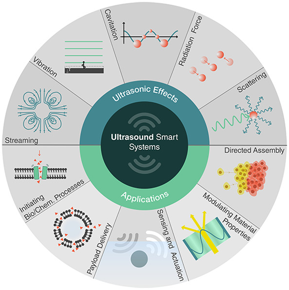
We consider how ultrasound can support six classes of smart capabilities, depicted in Figure 1. These range from directed assembly of smart materials, geometric reconfiguration of smart systems, sensing and actuation, payload transport and delivery, to the triggering of biological and chemical processes. These capabilities are enabled by different ultrasound-induced effects, namely, cavitation, microstreaming, structural vibrations, acoustic scattering, and the acoustic radiation force. This review explores the basis of these effects and how they can be utilized, tuned, and combined with other physical, chemical, and biological systems to enable unique responsive systems and smart material capabilities.
Figure 1.

Capabilities of smart materials enabled by ultrasound.
This review complements other recent reviews on subfields of acoustics (e.g., acoustofluidics,6 nanoacoustics,7,8 particle manipulation,9,10 and microbubble acoustics11) in both scale and scope. It is not restricted to any particular scale or single mechanism within acoustics. Rather, it aims to bring together all of the recent developments that can be applied in the development of smart and responsive systems. It focuses on the intersection of acoustics with smart systems and not only identifies mechanisms and techniques that could be useful for smart systems, but also explores emerging directions and open questions in this rapidly developing field.
2. Background: Acoustics and Ultrasound
2.1. What Are Acoustic Waves?
The field of acoustics deals with the transfer of energy through matter via mechanical waves. Generally, an acoustic wave is excited in a medium using a transducer, which converts electrical signals into vibrations that are transferred to the medium. These vibrations propagate through the medium as mechanical waves of compression and expansion. For many applications, it is necessary to understand how these waves will interact with any boundaries or objects that may be present. Ultimately, we want to use these underlying principles to describe and predict how acoustic waves will (1) transport energy or information to a recipient, such as a sensor, actuator or responsive material, and (2) how that information or energy can be converted into other forms of useful work.
Acoustic waves carry energy through compression and microscopic motion in a medium. While the acoustic waves are ultimately reliant on intermolecular interactions, it is easier to consider the wave causing motion of conceptual small bodies or “particles” in the medium, which represent a region much larger than the atoms or molecules but small enough that the wave behavior is effectively constant within. The acoustic wave can then be described continuously through the medium using different acoustic quantities: the pressurep, particle velocityv⃗, particle displacement ξ⃗, and density fluctuation ρ. As is seen below, these quantities can ultimately be used interchangeably, depending on the problem at hand. As a wave propagates, the acoustic quantities will vary in time and with the position in the medium, as shown in Figure 2. While it is possible to describe the propagation of a wave, it is common to refer to the shape of an acoustic field, which means the values of p, v, ξ, or ρ at every point in space, and usually indicates an interest in spatial patterns associated with the wave.
Figure 2.
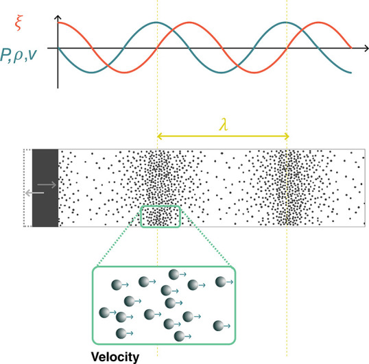
Acoustic waves generated by the motion of a boundary. Acoustic waves are mechanical waves of compression and rarefaction in a medium. Within the wave, the local pressure p, density ρ, particle velocity v, and particle displacement ξ vary as a function of time and position, with specific relationships between these variables. Density, pressure, and velocity oscillate in phase, while the displacement is 90° out of phase.
Acoustic waves are typically excited in a medium by a moving boundary. For instance, ultrasonic transducers use piezoelectric materials to convert electrical energy into mechanical vibrations. This oscillating boundary motion creates regions of high density (compression) and low density (rarefaction) that travel outward from the transducer, as shown in Figure 2. In the compressed regions pressures are higher than ambient pressure, while in the regions of rarefaction they are lower. Since the pressure varies in space, there is a net force in any given region of material, driving the local particle velocity.
An acoustic excitation travels through the material with a finite speed c, known as the material’s sound speed. In a fluid, the sound speed depends on the fluid’s equilibrium density ρ0 and its adiabatic bulk modulus K:12
| 1 |
In solids, wave propagation is more complicated because, in addition to compressional interactions, elastic solids also support shear interactions. Such shear coupling leads to a large number of different wave types that can propagate in solids, depending on geometry and mechanical properties. In the simplest case of an infinite (or very large) solid body, two types of waves can propagate: bulk compressional (longitudinal) and shear (transverse) waves. Their propagation speeds are given by
| 2 |
| 3 |
where G is the solid’s shear modulus. When interfaces are present, then additional wave types may propagate, including Rayleigh waves at an interface, flexural waves in a plate, and axial and torsional waves in bars, among others. In many cases, acoustic wave propagation in solids can be approximated considering only compressional wave behavior. This simplification is most accurate when waves propagate at normal incidence through a solid. Below, we will only consider acoustic waves in fluids and ignore elastic wave effects. A complete treatment of elastic waves can be found in standard texts.13 As indicated by eq 1, the stronger the bulk modulus (and thus the intermolecular forces), the higher the sound speeds: solids tend to have higher sound speeds than liquids, which in turn tend to have higher sound speeds than gases. (While the density suggests that the lower density of gases would increase the sound speed compared to solids, the bulk modulus changes more and, therefore, has a larger role in setting the sound speed.)
Most often, acoustic systems are driven harmonically, or sinusoidally at a single frequency f. In this case, p, v⃗, ξ⃗, and ρ will oscillate at the driving frequency in time, forming periodic waves in space with a wavelength λ = c/f. (This is true for small amplitude waves, but for large amplitudes or when significant nonlinearities are present, additional harmonics could arise.)
While acoustic waves span an enormous range of frequencies from below 1 Hz (atmospheric infrasound) to over 100 GHz (crystal lattice vibrations), this review is mainly concerned with ultrasound in the range 20 kHz–50 MHz. This range is of particular interest because these frequencies (1) fall outside the range of human hearing; (2) interact safely and with low losses in many materials including the human body; (3) have (relatively) small wavelengths in water (λ ≈ 15 mm at 100 kHz, 1.5 mm at 1 MHz, and 0.15 mm at 10 MHz), making them useful for interactions with small systems; (4) have short time scales (τ ∼ 1/f), making them useful for exchanging energy with fast phenomena; and (5) can be produced by many well-established transducer technologies across the frequency range and with large ranges of excitation pressures. Because the acoustic displacements themselves are rather small at high frequencies, it is instead often the very high accelerations associated with ultrasound that can drive strong effects in microscale systems.14
Depending on the system that is being analyzed, it is convenient to convert between the different acoustic quantities described above. These properties can be related to each other explicitly depending on the wave geometry. In most cases of interest, the wavefronts are planar and propagate in one direction (like those illustrated in Figure 2). In this case the acoustic quantities are related by12
| 4 |
| 5 |
| 6 |
where  is the imaginary unit. Equation 4 is derived from the equation
of state of the material and indicates that the acoustic density fluctuations
ρ are in phase with the acoustic pressure p: regions of high pressure correspond to compression in the medium
and regions of low pressure correspond to rarefaction as described
previously. For a plane traveling wave p and v are in phase as well, a fact that changes for curved wavefronts
or close to interfaces. The particle motion ξ associated with
the wave is proportional to the particle velocity, but 90° out
of phase. Moreover, the particle displacement decreases as the acoustic
frequency f increases for a fixed pressure. A p = 10 kPa plane wave in water causes particle motions of
1 nm at 1 MHz and 10 nm at 100 kHz, while a 1 MPa plane wave at those
frequencies causes motions of 100 nm and 1 μm, respectively.
By contrast, the density fluctuation and particle velocity are frequency
independent. A 10 kPa pressure wave in water is associated with a
particle velocity of v = 6.75 mm s–1 and a relative density change of ρ/ρ0 = 4
× 10–6. At 1 MPa, v = 675
mm s–1 and ρ/ρ0 = 4 ×
10–2.
is the imaginary unit. Equation 4 is derived from the equation
of state of the material and indicates that the acoustic density fluctuations
ρ are in phase with the acoustic pressure p: regions of high pressure correspond to compression in the medium
and regions of low pressure correspond to rarefaction as described
previously. For a plane traveling wave p and v are in phase as well, a fact that changes for curved wavefronts
or close to interfaces. The particle motion ξ associated with
the wave is proportional to the particle velocity, but 90° out
of phase. Moreover, the particle displacement decreases as the acoustic
frequency f increases for a fixed pressure. A p = 10 kPa plane wave in water causes particle motions of
1 nm at 1 MHz and 10 nm at 100 kHz, while a 1 MPa plane wave at those
frequencies causes motions of 100 nm and 1 μm, respectively.
By contrast, the density fluctuation and particle velocity are frequency
independent. A 10 kPa pressure wave in water is associated with a
particle velocity of v = 6.75 mm s–1 and a relative density change of ρ/ρ0 = 4
× 10–6. At 1 MPa, v = 675
mm s–1 and ρ/ρ0 = 4 ×
10–2.
As was described above, acoustic waves carry energy, which can be used to perform useful work. The energy density carried by a plane wave is given by12
| 7 |
where P and V are the acoustic pressure and velocity amplitudes.
Another commonly used metric for describing energy propagation in a wave is the wave intensity, which quantifies the rate of energy transfer by the acoustic wave (in units of W cm–2). The time average intensity for a plane wave in a fluid can be calculated directly from the pressure and fluid properties:
| 8 |
The strength of an acoustic field is sometimes reported as a pressure and sometimes as an intensity, depending on the application or conventions in a research field. Therefore, it is valuable to be able to convert between these two descriptions. Moreover, because energy must always be conserved, eq 8 is a useful tool to estimate pressure amplitudes in different systems, such as when sound is transmitted from a material with one set of material properties (ρ0, c) into another (ρ0′, c′). Similarly it helps to estimate the pressure produced by a transducer emitting a power W from an active area A. In this case, the intensity should scale as I ∼ W/A, which allows us to estimate the pressure generated in the propagation medium with (ρ0, c). Exemplary values for acoustic pressure and intensity in water are given in Table 1 as a reference, since most of the systems described in this review occur in an aqueous environment.
Table 1. Relationship between Acoustic Intensity and Pressure for Plane Waves in Water.
| pressure | intensity |
|---|---|
| 1 kPa | 3.3 × 10⁻⁵ W cm–2 |
| 10 kPa | 3.3 × 10⁻³ W cm–2 |
| 100 kPa | 0.33 W cm–2 |
| 1 MPa | 33 W cm–2 |
After considering how acoustic waves carry energy through materials in the form of pressure, density, and local velocity fluctuations, we will discuss how different materials and geometries impact the acoustic response of a system and the associated energy transfer.
2.2. Controlling Acoustic Waves
2.2.1. Acoustic Properties of Materials
The acoustical and geometrical properties of a medium dictate how effectively energy can be transported between two points. This also opens up opportunities to control the wave and energy propagation by structuring materials appropriately. Commonly, a material’s acoustic properties are described by its acoustic impedance Z = ρ0c, which describes the resistance of a medium to move given a fixed pressure excitation (see eq 5). A high-Z material will exhibit smaller particle velocity for a fixed excitation pressure. Conversely, a fixed vibration amplitude of a surface (such as a transducer) will produce lower pressures in a low-Z material. The acoustic impedance determines the behavior of waves at the interface between different media. If an acoustic wave is incident on a flat interface between two media with impedances Z1 and Z2, sound will reflect backward from the interface with a reflection coefficient:
The fraction of the incident
energy
reflected back from the interface is given by |R|2. Acoustic waves couple more efficiently from one medium to
another if their impedances are similar, so R →
0. The acoustic impedance therefore determines how strongly acoustic
waves are scattered or reflected from an interface, and this can have
important implications when designing acoustic systems such as resonators
or when trying to control materials with sound, e.g., using the acoustic
radiation force, as will be seen below. As a reference, the values
of ρ0, c, and Z are provided for some common materials in Table 2. To improve acoustic transmission between
highly disparate media, as often encountered in transducer design,
matching layers can be used. For example, ideal transmission can be
achieved between two interfaces by adding a thin layer between them,
with impedance  and thickness λ3/4 (where
λ3 = c3/f). The thickness constraint restricts this concept to work only in
a narrow frequency band. In practice, two or more consecutive matching
layers are often used to provide more robust broadband matching. Alternatively,
broadband matching layers have been reported using gradient-index
metamaterials, which are structures with subwavelength features that
change the bulk properties for acoustic waves (cf. gradient index
materials in optics).15
and thickness λ3/4 (where
λ3 = c3/f). The thickness constraint restricts this concept to work only in
a narrow frequency band. In practice, two or more consecutive matching
layers are often used to provide more robust broadband matching. Alternatively,
broadband matching layers have been reported using gradient-index
metamaterials, which are structures with subwavelength features that
change the bulk properties for acoustic waves (cf. gradient index
materials in optics).15
Table 2. Acoustic Properties of Selected Materials at Room Temperature (20 °C)a.
| material | ρ (kg m–3) | c (m s–1) | Z (Pa s m–1) | a (dB cm–1) | notes | ref |
|---|---|---|---|---|---|---|
| air | 1.2 | 343 | 412 | – | 20 °C | (12) |
| water | 997 | 1482 | 1.5 × 10⁶ | 2.2 × 10⁻³ | at 100 kHz | (18, 19) |
| 0.22 | at 1 MHz | (19) | ||||
| brain tissue | 1035 | 1562 | 1.6 × 10⁶ | 0.58 | at 1 MHz, 37 °C | (20) |
| bone | 1990 | 3198 | 6.4 × 10⁶ | 3.54 | at 1 MHz, 37 °C | (20) |
| glycerol | 1260 | 1904 | 2.4 × 10⁶ | – | (21) | |
| silicone oil | 818 | 960 | 0.8 × 10⁶ | – | Dow 200, 1 cSt viscosity | (21) |
| PDMS | 1031 | 1028 | 1.1 × 10⁶ | 0.4 | at 3 MHz | (22) |
| PMMA | 1191 | 2690 | 3.2 × 10⁶ | 0.7 | at 1 MHz | (23) |
| silica glass | 2200 | 5900 | 13 × 106 | – | (24) | |
| brass | 8470 | 4494 | 38 × 106 | – | C38500 alloy | (24) |
ρ, density; c, sound speed; Z, impedance; a, attenuation coefficient.
An additional important material property when designing acoustic systems is the material attenuation coefficient. Attenuation describes the loss of acoustic energy irreversibly to heat through various mechanisms such as viscosity or molecular relaxation.12 When an acoustic wave propagates in material, the pressure amplitude after a distance L is given by p = p0e–αL, where p0 was the initial pressure of the wave and α is the attenuation coefficient in neper per centimeter. More commonly, the attenuation coefficient is expressed as a = 8.7α, which is given in units of decibels per centimeter. Attenuation depends strongly on frequency, and higher frequencies are attenuated more strongly than low frequencies. Empirical models typically describe this dependence as a power law: a(f) = a0fγ, where 0 < γ ≤ 2. To describe a material’s attenuation at all frequencies, it is therefore sufficient to know the value of a at one frequency, the frequency at which a was measured, and the power γ. For liquids including water γ = 2,16 while for many polymers including PMMA the relation is almost linear (γ ≈ 1).17Table 2 provides the attenuation coefficient a and measurement frequency for a few select materials.
2.2.2. Effects of Geometry on Acoustic Waves
In addition to the choice of material, a material’s geometry can also be used to control the propagation of acoustic waves. Ultrasound transducers are typically designed to emit plane waves, as shown in Figure 3a. When a plane wave is incident on the interface between two different materials, part of the energy will be reflected and part will be transmitted, as described above. When the interface is planar, the transmitted portion of the wave will bend, or refract, as shown in Figure 3b. Refraction depends on the sound speeds of the two media and the angle of incidence: stronger refraction will take place between two media with very different sound speeds. A nonplanar interface will lead to more complex refraction and reflection and, therefore, can produce more complex acoustic fields. For example, a curved interface can be used to focus acoustic waves, as shown in Figure 3c. While lenses are commonly designed for use in transmission as depicted here, it is also possible to use a curved reflective surface to focus sound as well. Refraction is not inherently frequency dependent; however, when curved interfaces are used, the focusing properties will depend on the relative magnitude of the focal length and the wavelength, making lenses frequency dependent. For a fixed lens geometry, higher-frequency ultrasound can be focused to a smaller spot than lower-frequency ultrasound.
Figure 3.

Methods to shape ultrasound fields. (a) A simple piston transducer approximately produces a plane wave in a uniform medium. (b) When the plane wave transmits into a medium of a different sound speed, refraction causes the wave direction and wavelength to change. (c) A lens can be used to focus plane waves to a point. (d) An acoustic hologram provides more control to turn a plane wave into an arbitrarily shaped pressure field. (e) A resonator can be built to create a high-amplitude patterned pressure field using two opposing transducers or a transducer and a reflector.
Recently, powerful techniques have been developed to shape acoustic fields using acoustic holograms, as shown in Figure 3d.25 Acoustic holograms use algorithmically designed interfaces to shape an incident acoustic plane wave so that it forms a desired (and arbitrary) field shape after a certain propagation distance. Acoustic holograms have been used to create pressure fields patterned with very high complexity, and they can be tailored to each specific application much more flexibly than a conventional focusing element such as a lens. Similar to lenses, acoustic holograms can be designed for use in transmission geometries (as depicted) or in reflection, and the resolution of the features that can be produced increases with the frequency.
Interface geometry also plays an important role when more complex wave types are used. Surface acoustic waves (SAW) are waves that propagate only at interfaces between two media and can be used to confine and guide energy along a specific path, which is finding increasing application in microscale devices.14 When at least one of the media is solid, then the interface geometry can also strongly determine what kinds of waves can be reflected. In some cases, the geometry can prevent certain kinds of elastic or surface waves from being generated, while in other cases it can be used to efficiently convert energy between different propagating wave types.13 While such mode conversion is sometimes a source of undesired losses, it is also a common technique used when designing transducers to excite specific kinds of waves.26 Increasingly, custom surface designs (metasurfaces) are being explored to produce specific and tunable reflection or refraction behaviors.27 However, these techniques are currently used in the audible (low-kilohertz) frequency ranges, and scaling the structures down for use at megahertz frequencies remains an open challenge.
Finally, acoustic fields can be shaped and amplified by confining them in space within a resonator. Resonators can be designed in different shapes and configurations, but the simplest resonator is a homogeneous medium between two rigid walls, separated by a distance L = nλ/2 = nc/(2f), for any integer n. Such a resonator geometry is shown in Figure 3e. Acoustic waves in a resonator propagate in both directions—either because of reflection off one wall or because of being driven by two opposing transducers. The opposite-traveling waves interfere and produce a standing wave pattern, which is fixed in space. For the best performance, it is critical that the walls are properly spaced at the resonant distance. When this condition is satisfied, constructive interference leads to a strongly amplified field in the resonator, in the form of a regular grid of high- and low-pressure regions that can be used for different applications, such as trapping and manipulation of small objects. Because the performance is dependent on the boundary spacing L, resonators are typically designed to operate at one frequency.
2.2.3. Bubbles
Because of their geometry and mechanical properties, gas bubbles constitute a special class of acoustic material that is used heavily in emerging ultrasound technologies. While they are not typically used to shape acoustic fields, their response to acoustic fields can be tuned and measured for different applications. Bubbles are unique acoustic objects because they can produce large acoustic and vibrational responses to sound whose wavelength is much larger than the bubbles themselves. For the description here and the discussion in the following sections, we will only consider subwavelength spherical air bubbles in water.
The mechanical properties of gas bubbles are responsible for their strong response. Gas bubbles are highly compressible and behave like a spring when excited by ultrasound: they store energy in compression and expansion cycles and release it as kinetic energy within the surrounding fluid. Bubbles are therefore resonant objects, whose response can be amplified by driving them at their resonance frequency. Resonant excitation leads to large amplitude motion of the bubble walls and a stronger scattering response for sensing. A resonant bubble can reflect over 100 times more energy than expected on the basis of its size alone.28
The fundamental resonant frequency of a bubble is known as the Minnaert frequency fM, which is set by the bubble size, properties of the gas, and properties of the fluid:28,29
| 9 |
Here, R is the bubble radius, κ is the polytropic coefficient for the gas, pA is the ambient pressure, and ρ0 is the density of the surrounding liquid. Additional factors, such as surface tension, shift the resonant frequency from this idealized value;28,30 however, the Minnaert frequency provides a good starting estimate for a bubble resonance in most cases. A 1-μm-diameter air bubble in water is resonant near 6.6 MHz; at 10 μm, the resonance drops to around 660 kHz, and at 100 μm it drops to 66 kHz.
The properties of the medium surrounding the bubble can also have a decisive effect on the bubble’s resonance. In many applications, small microbubbles are encapsulated in viscoelastic shells to stabilize them against gas diffusion. In other situations, bubbles may be embedded in a complex medium such as a gel. In these cases, the resonance frequency and resonant response will depend on the shell or medium properties as well.31 If a bubble is partially enclosed by a rigid structure, then it cannot expand symmetrically, and it will also exhibit altered resonance behaviors. When the bubble is enclosed in a cavity, higher-order interfacial resonances can be observed, where the bubble interface oscillates like a pinned membrane.32,33
Bubbles can be turned into tools by feeding them energy with an external sound field, causing the bubble to oscillate. These oscillations have two important effects. First, they can emit sound themselves (a scattered acoustic wave), creating a point source of sound that can be remotely measured. Second, they can generate strong fluid flows that can be used to apply fluid stresses to objects at the microscale and molecular scale. These streaming effects are often amplified in the presence of rigid boundaries and structures.
The strength of these different bubble responses depends primarily on the size of the bubble (which sets the resonance frequency) and the driving ultrasound frequency. For scattering, the strength is quantified by the scattering cross section of the bubble, which indicates how much of the incident energy is scattered by the bubble. At low frequencies (excitation f ≪ fM), the scattering cross section depends most strongly on the frequency, increasing as (f/fM)4. At resonance (f = fM), the cross section only depends on the resonance frequency of the bubble, scaling as fM–2 or, equivalently, as R2. The larger the bubble, the stronger its resonant response will generally be.28 The strength of streaming responses from bubble excitation is more complicated and also depends strongly on the presence of boundaries around the bubble. These effects are discussed more in sections 2.3.2 and 3.6.1. Another way to increase the response strength of a bubble is to increase the amplitude of a driving field. However, after a certain point, large vibration or pressure amplitudes will lead to nonlinear bubble oscillations34 and cavitation, which is discussed more in section 2.3.4.
Because they can convert acoustic energy into other forms of energy such as fluid flow, bubbles can also serve as sources of loss for acoustic waves. In general, bubbles will lose energy through one of three mechanisms: thermal losses during gas compression, viscous losses in the fluid, and acoustic scattering. Depending on the size of the bubble, different loss mechanisms dominate.30 For air bubbles in water that are larger than 10 μm, viscous forces are negligible, and thermal losses dominate at low frequencies while acoustic radiation dominates at high frequencies. For smaller bubbles, viscous losses become significant at low frequencies, but the high-frequency damping response is still dominated by acoustic radiation.30
2.3. Using Acoustic Energy
When ultrasound is used for smart systems, one important goal is to use the acoustic waves for nonacoustic work, such as moving objects, initiating chemical reactions, and mechanically triggering biological processes. In order to achieve this, it is necessary to convert the acoustic energy. Sometimes this is because the final action is inherently another form of work, e.g., electrical or chemical. Other times, it is because the target system cannot respond strongly to mechanical stimuli at ultrasonic frequencies. In either case, mechanisms are required that can convert the acoustic energy into a more useful form for the task at hand. In this section, we describe four mechanisms that are commonly used for this purpose: piezoelectricity (section 2.3.1), acoustic streaming (section 2.3.2), acoustic radiation forces (section 2.3.3), and cavitation (section 2.3.4).
2.3.1. Piezoelectricity
Piezoelectric materials are noncentrosymmetric materials that generate an internal electrical polarization in response to an applied mechanical stress. Consequently, the (inverse) piezoelectric effect can be used to produce motion and therefore acoustic waves from an externally applied electrical voltage. Piezoelectricity can be observed in crystals such as quartz, ceramics such as lead zirconate titanate (PZT), and polymers such as polyvinylidene fluoride (PVDF). The strength of the piezoelectric effect can be quantified by the longitudinal piezoelectric coefficient d33, which describes how much the material will deform for a given voltage. A typical value for commercial PZT is d33 = 265 × 10–12 m V–1 (PIC181, PI Ceramic, Germany). In addition to being useful for converting electricity into motion, piezoelectric materials can also convert sound into electrical signals via the direct piezoelectric effect. Beyond applications for sensing ultrasound, the direct piezoelectric effect can be used to generate voltages that can be used to trigger chemical processes and biological signaling, as discussed in section 3.
2.3.2. Acoustic Streaming
In order to directly convert high-frequency ultrasonic waves into steady forces on objects, it is necessary to make use of nonlinear acoustic mechanisms. The first nonlinear acoustic mechanism that can be used for this purpose is acoustic streaming.35 Acoustic streaming refers to fluid flow driven by acoustic waves, which is caused by momentum transfer from the acoustic waves to the fluid. This can occur at the fluid boundary layer along vibrating bubbles or structures, where the dissipation of acoustic energy due to the steep velocity gradient induces boundary layer streaming, called Schlichting streaming.36 Driven by the shear of this boundary layer streaming, there will be a flow in the bulk fluid called Rayleigh streaming, as shown in Figure 4a,b.37 Acoustic streaming can also occur in a bulk fluid because of attenuation of the propagating wave. This is known as Eckart streaming and is shown in Figure 4c.38
Figure 4.

Different mechanisms can be used to convert ultrasonic energy into other forms for useful work. (a) Bubble vibration induced streaming. (b) Microstructure vibration induced streaming. (c) Acoustic streaming induced by acoustic wave propagation and attenuation. (d) Acoustic radiation force. (e) Acoustic contrast factor as a function of particle and fluid properties, with specific values plotted for common acoustic materials in water.
Rayleigh streaming is strongest when a structure, such as a bubble or a beam, is excited on resonance, causing maximal vibrations. The resonance frequencies of elastic structures are dependent on their size, geometry, and mechanical properties. When driven by a fixed acoustic intensity, high-aspect-ratio or sharp-edged structures generally provide a stronger streaming response than low-aspect-ratio structures. The oscillation of these resonant microstructures will induce intense Schlichting streaming in the surrounding fluid boundary layer, which will generate strong Rayleigh streaming in the nearby bulk fluid.39 Rayleigh streaming can also happen when a surface acoustic waves propagate along a solid boundary, which typically has a higher frequency than the resonant microstructures.14
In the presence of acoustic streaming, any structures or particles in the flow will experience a drag force caused by the viscosity in the fluid. At small length scales, the fluid flow is typically dominated by viscous effects, and the viscous stress applied to a boundary by a fluid moving with velocity v and viscosity μ is given by τ = μ∇v⃗. The shear stress from a fluid is proportional to viscosity and to the gradient of the velocity, which is also known as the strain rate. Small objects in the flow, such as microparticles, will be carried along with the flow unless they are held in place by other forces (e.g., magnetic, electrostatic, or acoustic radiation forces). Soft structures and macromolecules, on the other hand, can be deformed by the drag forces, or even broken by them if the shear rate is high enough.40
2.3.3. Acoustic Radiation Forces
The second nonlinear mechanism that can be used to create steady forces is the acoustic radiation force (ARF).41 Acoustic radiation forces can be experienced by surfaces, structures, or microparticles exposed to ultrasonic waves (see Figure 4d). Most commonly, we will discuss the acoustic radiation force on microparticles that are much smaller than the acoustic wavelength.
For a uniform spherical particle suspended in a liquid, the ARF is dependent on the properties of both the acoustic field (i.e., the intensity and frequency) and particles (i.e., the size and acoustic properties relative to the surrounding media). Following a classic model for the acoustic radiation force,42 the ARF on an elastic spherical particle can be calculated as the gradient of a potential FARF = −∇UARF, which is in turn proportional to the particle volume V, acoustic contrast factor Φ of the particle, and the acoustic intensity I: UARF ∝ IΦV. The acoustic contrast factor measures the difference in acoustic properties between the particle and the surrounding fluid and is given by43
| 10 |
where the subscripts “p” and 0 refer to the particle and the surrounding medium, respectively. The acoustic contrast factor is plotted in Figure 4e as a function of ρp/ρ0 and cp/c0. The values of Φ for selected materials are labeled as well. As seen in the plot, the amplitude of the acoustic contrast factor—and therefore the strength of the ARF—increases as the particle and liquid become more acoustically different. For example, in the same acoustic field, the acoustic radiation force on a silica microparticle will be higher than that on a same-sized polystyrene microparticle. In comparison, a cell, which is mostly water, will experience a much lower ARF than either of the solid microparticles.
In general, materials with positive acoustic contrast (Φ > 0) move against a spatial pressure gradient and eventually accumulate in the pressure nodes (where p = 0), as shown in Figure 4d. Materials with negative acoustic contrast on the other hand are attracted to antinodes (where the pressure amplitude is maximal). Particle manipulation and directed assembly or tweezing at fixed locations can thus be achieved by carefully designing structured acoustic fields, e.g., by using a lens,44 hologram,25 diffractive element,45 or resonator.46
It should be noted that this model of the ARF only applies to simplified conditions where the particle diameter is much smaller than the acoustic wavelength of the medium and the shear acoustic waves in the particles are neglected. When these assumptions cannot be satisfied, more complex models can provide more accurate predictions for the ARF.47
A special case of ARF is experienced by bubbles in an acoustic field and can be broken into two parts: the primary and secondary Bjerknes forces.28,48,49 Primary Bjerknes forces arise on an isolated bubble in an acoustic field and are given by F⃗B1 = −V∇P, where V is the bubble volume, P is the acoustic pressure amplitude, and ∇ is the spatial gradient operator. Primary Bjerknes forces arise from slight differences in the pressure that a bubble experiences at different points in its oscillation. The primary Bjerknes force pushes bubbles toward regions of high pressure when they are excited below resonance (bubble smaller than the size resonant with driving field) and toward regions of low pressure when they are excited above resonance (bubble larger than resonant size). The secondary Bjerknes force emerges between two or more bubbles in an acoustic field, through the pressure fields scattered by each bubble. The secondary Bjerknes force can be attractive or repulsive depending on the bubble sizes and the driving frequency. Because the secondary Bjerknes force depends on the scattered field, it is shorter range and typically weaker than the primary Bjerknes force. However, when many bubbles are aggregated within a region of low pressure, such as at the nodes of a resonator, the secondary Bjerknes forces can play an important role, leading to motion, rearrangement, and clustering behavior of the bubbles. Elastic particles can experience similar secondary radiation forces based on scattered waves.50
2.3.4. Cavitation
A final and important mechanism to convert acoustic energy into other forms is cavitation.51 During cavitation, an acoustic wave causes bubbles to form, oscillate, and potentially collapse in a fluid. Because of the strong response of bubbles to ultrasound, significant amounts of energy can be transferred from an ultrasound wave into bubble motion during the cavitation process. Between the large amplitude motion and the violent bubble collapse, cavitation can provide both strong mechanical and thermal stimuli. Additionally, during bubble collapse, a small plasma can form (sonoluminescence), which can also play an important role in optical and chemical processes. During bubble collapse, the temperature can briefly (<1 μs) reach several thousand kelvin and pressures on the order of tens of megapascals. These extreme conditions are associated with plasma formation in the collapsing bubble, which can produce radical species and emit electromagnetic radiation known as sonoluminescence.52
Cavitation occurs when the rarefaction (negative) pressure in an acoustic wave is low enough to draw dissolved gases out of solution into bubbles. This effect is more likely at lower frequencies, where the duration of strong negative pressure is longer each cycle than at higher frequencies. If nucleation sites are present in the fluid, such as micro- or nanoparticles, or rough surfaces, then cavitation can typically occur more easily. Similarly, if a fluid already contains microbubbles, then the effects of cavitation can be observed more easily. Conversely, cavitation effects can be suppressed by degassing the fluid.
A metric that indicates the strength of cavitation effects in aqueous systems with microbubbles is the mechanical index (MI):28
| 11 |
where Pnp is the
peak negative pressure in an acoustic wave in MPa and f0 is the frequency in MHz. While the MI is calculated
in units of  , it is commonly reported without
the units.
At low MI (MI < 0.1), microbubbles only scatter the ultrasound
signal (linear backscattering). At intermediate MI (0.1 < MI <
0.4) the bubble response becomes nonlinear, with increased scattering
at harmonic and subharmonic frequencies34 (integer multiples or fractions of the driving frequency), due to
large stable volumetric oscillations. This regime, which is referred
to as stable cavitation, can induce slow bubble destruction via diffusion
depending on the gas solubility in the surrounding medium. At higher
MI (MI > 0.4), microbubbles will violently oscillate to the point
of their collapse, emitting acoustic waves in a wide range of frequencies.
This regime is known as inertial (or unstable) cavitation.
, it is commonly reported without
the units.
At low MI (MI < 0.1), microbubbles only scatter the ultrasound
signal (linear backscattering). At intermediate MI (0.1 < MI <
0.4) the bubble response becomes nonlinear, with increased scattering
at harmonic and subharmonic frequencies34 (integer multiples or fractions of the driving frequency), due to
large stable volumetric oscillations. This regime, which is referred
to as stable cavitation, can induce slow bubble destruction via diffusion
depending on the gas solubility in the surrounding medium. At higher
MI (MI > 0.4), microbubbles will violently oscillate to the point
of their collapse, emitting acoustic waves in a wide range of frequencies.
This regime is known as inertial (or unstable) cavitation.
Different mechanical effects can be induced by ultrasound via cavitation, depending on the MI.53 The linear and nonlinear re-emission of sound at low to intermediate MI is the basis for the use as ultrasound contrast agents.54 Additionally, the increase in volumetric oscillation amplitude at intermediate MI is responsible for microstreaming flows.55 Bubble collapse at high MI may be accompanied by the emission of a shock wave.52,55 Microstreaming and collapse both will impose shear stresses on nearby structures. If the bubble is close to a surface, such as a container wall or another bubble, it can exhibit highly nonspherical oscillations that at intermediate MI values give rise to microstreaming velocities on the order of 1 mm s–1.55 At higher MI, collapsing bubbles near a surface can generate a liquid microjet that can cause damage to solid structures.
In addition to inducing mechanical effects, cavitation can also convert acoustic energy into heat.55 Three mechanisms may be involved in heat generation, depending on the size of the bubble, ultrasound parameters, and viscosity of the medium. The first one is heating of the surroundings due to the nonlinear acoustic radiation. The second effect is heating through viscous dissipation in the liquid during bubble motion. The third effect is thermal conduction through the gas core during compression of the bubbles. Heating due to nonlinear acoustic emission typically dominates in biomedical applications.55
2.3.5. High- and Low-Intensity Ultrasound
The nonlinear effects described in this section all typically require high pressures or intensities to be realized. The use of high-intensity ultrasound often comes with additional instrumentation challenges and risks for damage, e.g., in sensitive biological systems. Therefore, it is often desirable to operate with lower power acoustic systems when possible. However, there are no clear boundaries between high- and low-intensity (or power) ultrasound, and different definitions are adopted by different authors. Here, we will avoid arbitrarily defining a boundary between low- and high-intensity ultrasound, and instead we will always provide the intensity or pressure levels in our descriptions.
Nonetheless, certain metrics are still valuable reference points for high-intensity ultrasound. As described above, the mechanical index can indicate when different detrimental effects of cavitation can be expected. In addition, guidance from the United States Food and Drug Administration (U.S. FDA) regarding safe operating levels for medical ultrasonic devices56 is often adopted as guidelines for other applications. The FDA defines maximum allowable intensities based on the MI and two intensity metrics: the spatial-peak pulse-average intensity (ISPPA) and the spatial-peak temporal-average intensity (ISPTA). ISPPA is the time-average intensity over the duration of a pulse, whereas ISPTA is the time-average over a longer time frame, therefore applying to continuous excitation as well. The maximum allowed intensities depend on the target tissue, but maximum permissible values for peripheral vessels are defined as ISPTA = 720 mW cm–2 and ISPPA = 190 W cm–2 or a mechanical index MI = 1.9. Higher values result in a temperature increase via absorption and thus can lead to cell death above 43 °C.
In section 3, acoustic effects and properties described here will be built upon to shape, trigger, interrogate, and actuate materials.
3. Acoustic Responses for Smart Materials
3.1. Patterning and Assembly of Biological Materials
Living biological matter can be seen as a blueprint for smart materials, as it can self-organize and act in response to cues from the environment. It is therefore of interest to build new hybrid smart materials from living components, such as cells. However, patterning and assembling functioning cellular structures—let alone synthetic organs—using biological building blocks is still a major challenge.57,58 Acoustic waves are benign to cells and can be used to assemble and shape biological matter via fluid streaming or the acoustic radiation force. The resulting forces can move biological cells and push them into predefined locations. It is also possible to align and assemble different cell types into functioning cell aggregates and simple organoid-like structures. These acoustic bioassemblies are promising for biomedical research, including drug screening,59 tissue engineering,60,61 and disease modeling.62
Acoustic assembly techniques complement other techniques that have also been developed for these purposes, and they generally offer advantages for assembly in certain circumstances. For instance, optical tweezers have found widespread use in the manipulation and assembly of individual cells and small particles. A recent review by Dholakia et al.10 highlights some of the key differences between optical and acoustic techniques for manipulation. Ultrasound is shown to generally provide higher trapping forces than light, while sacrificing some of the force sensitivity and spatial precision of optical techniques. Acoustic patterning and assembly also offers the advantages of good biocompatibility, rapid and parallel control of large numbers of cells, and efficient transmission for long-range control of assembled systems.
The acoustic methods that are predominantly used in the patterning and assembly of cells can be divided into three categories, as shown in Figure 5: standing wave trapping,63,64 Faraday wave patterning,65−67 and holographic patterning.68,69
Figure 5.
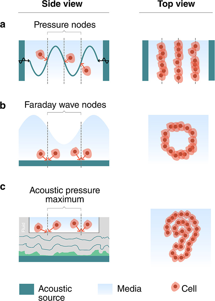
Acoustic patterning and bioassembly. (a) Standing wave trapping of cells in a resonator, (b) Faraday wave patterning, and (c) holographic acoustic patterning.
Standing wave trapping (Figure 5a) is based on the acoustic radiation force experienced by cells when they are exposed to a standing acoustic wave. As described in section 2.2.2, standing acoustic waves are most commonly formed by opposing pairs of acoustic sources63 or by a resonant cavity that is excited by a single acoustic source.70 The acoustic radiation forces in these systems range from ∼1 pN to ∼10 nN. Biological cells will typically be trapped at the pressure nodes and, accordingly, form highly symmetric assemblies and periodic patterns.
Faraday waves (Figure 5b) are forced surface ripples that form at the liquid–air interface of a bounded liquid. They are typically generated by low-frequency vibrations (40–200 Hz) and display a vertical surface deformation, which causes recirculating flows in the fluid. These flows can carry suspended cells via the Stokes drag toward the stagnation points, which are located below the nodes of the surface waves. Faraday waves are enhanced when the excited at resonance frequencies of the container. Cells have been assembled into simple shapes, such as periodic straight or curved lines.65
Holographic particle patterning9 (Figure 5c) uses holograms to shape the acoustic field for the assembly of cells.68 Acoustic fields can be holographically patterned using a 3D-printed holographic phase mask,25,71 a phased array transducer,72−74 or a spatial acoustic modulator.75 Unlike standing waves and Faraday waves, holographic sources can potentially shape arbitrary complex fields that are independent of the container geometry. Thus, holograms can assemble cells into nonsymmetrical and irregular patterns. Both acoustic streaming and acoustic radiation forces can be used to aggregate cells in areas of high acoustic pressure.68
Patterning and assembling cellular structures offers the opportunity to use them as actuators and components in the development of miniaturized robotic systems.76 There has been considerable progress in using acoustic fields to align muscle cells (e.g., cardiomyocytes, myoblast cells) into tissuelike structures, which naturally actuate. Natural muscle tissue is organized along fibers, so the objective of the acoustic cell assembly is to form lines of cells. Armstrong et al.60 demonstrated acoustic assembly of myoblasts using standing acoustic waves (Figure 6a–c). Prior to the experiment the cells were suspended in a pre-cross-linked hydrogel. Then a standing pressure wave was generated between two pairs of opposing transducers to pattern the cells into periodic stripes whose pitch could be tuned by varying the frequency of the acoustic field. To immobilize the cell pattern, after assembly the hydrogel was cross-linked with UV light or slight heating. The cell patterns could then be incubated and formed tissue constructs with oriented multinucleated myotubes bundled into parallel, aligned muscle fibers. Tensile tests confirmed an increased Young’s modulus in the fiber direction. The assembled muscle tissue also responded to pulsed electrical stimulation. Ren et al.66 demonstrated the assembly of fibroblasts into ring-shaped structures using Faraday wave patterning (Figure 6d–g). The cell patterning was performed in a pre-cross-linked hydrogel (alginate), which was cross-linked after assembly with an ionic trigger (addition of calcium chloride) to immobilize the cell assembly for culturing. After 24–72 h the cells located on the outside of the ring showed radial alignment, while those on the inside showed circumferential alignment. The surrounding hydrogel could be dissolved and the cellular rings could be further assembled into tubular or concentric ring structures by using Faraday waves. The cellular assembly depends on the pattern of standing Faraday waves; thus its shape and size can be tuned by changing the container size or vibration frequency.65 This flexibility in cellular assembly could be potentially used in tuning the cell alignment and the mechanical properties of the assembly.
Figure 6.

Acoustic assembly of cells to form actuators. (a–c) Patterning of fibroblast cells into stripes by standing acoustic wave trapping. Adapted from ref (60). CC BY 4.0. (d–g) Ring-shaped cell structures via Faraday wave patterning. Adapted with permission from ref (66). Copyright 2019 Wiley-VCH.
Acoustic cell assembly has also been used for the development of simple cellular models for neural and brain studies.77 Organoids assembled from preselected cell types have been used to mimic specific brain regions, such as forebrain, midbrain, and cerebral cortex. The aforementioned work of Faraday wave cell patterning66 also demonstrated the acoustic assembly of simple brain organoids (Figure 7a,b). To mimic native brain tissue, the authors separately assembled neuron-rich and astrocyte-rich cellular rings, both from E18 mouse cells. Those were placed concentrically in a medium and cultured together for 14 days. The brain surrogate presented a viability of 87% after 7 days. The neurons in this simple brain organoid model showed synchronized calcium activity, indicating the formation of a network of neurons.
Figure 7.

Acoustic assembly of neuronal and simple brain models. The bioassemblies show similar characteristics as the real organs. Native mouse brain (a) with an outer layer of neuron-rich cells and a neurite tract and a layer rich in glial cells. The acoustically assembled cells (b) exhibit similar features. Panels a and b reproduced with permission from ref (66). Copyright 2019 Wiley-VCH. (c, d) An acoustically aggregated brain organoid for Alzheimer’s disease modeling. Neuron inflammation depends on the presence or absence of amyloid-β in the environment. Reproduced with permission from ref (78). Copyright 2020 RSC Publishing.
Acoustic bioassembly can be used to build disease models of brain tissue. Cai et al.78 used standing wave trapping to aggregate brain cells (including neurons, microglia, and astrocytes) and amyloid-β aggregates (potential key contributors to Alzheimer’s disease79) into spheroids to mimic the neuroinflammation process in Alzheimer’s disease (Figure 7c,d). Compared to the control group of spheroids without amyloid-β aggregates in the environment, the disease model spheroid showed a significantly higher expression of microglia activation, which is consistent with signs of neuroinflammation.80 Acoustically assembled spheroids can therefore potentially be used as convenient in vitro models for research into Alzheimer’s and other diseases.
The patterning and assembly of cells and living tissues using acoustics offers a versatile and benign route to construct biological smart materials, such as bioactuators and (brain) organoids. There is room for improvement to increase the complexity and functionality of the bioassemblies that can be generated with acoustic fields. Also, it is known that a 3D spatial control of the distribution of cells will extend the functionality81 and facilitate the integration of the bioassemblies with artificial microstructures.82 However, 3D control has yet to be shown with acoustic methods. In addition, some studies have shown that cells can assemble into spheroids in acoustic streaming flows.83−87 The flow enriches the cell concentration at the vortex center and also disturbs the cell adherence to the container surface; thus it enhances the formation of cellular spheroids. For future studies, precise and high-throughput control of the acoustic streaming profile could open up new directions in the patterning and assembly of biological materials. Going further, more studies can be expected to investigate the influence of acoustic waves on cellular properties that are important for long-term cell patterning and assembly. Such properties include proliferation,88,89 viability,90 metabolic activity, and differentiation. Finally, the ability to select the cell type during the assembly would open up the possibility to enable vascularization in the bioassembly,91−93 which is important for larger scale structures, and to realize the growth of real organs or tissues with acoustic fields.
3.2. Reconfiguring Shape and Material Properties
Acoustic fields can be used to change the shape and microstructure of a material, opening up pathways to control its functionality. Three physical mechanisms (Figure 8) provide a means to affect different material properties: (1) pressure waves can be used to modulate the density of a medium, (2) the acoustic radiation force on particles and molecules can be used to modify the structure and behavior of microstructured materials, and (3) the acoustic radiation force can change the geometry of interfaces. In this section we review how these mechanisms have been exploited to achieve different functionalities relevant to smart materials, focusing on examples where ultrasound has been used to control the propagation of light (section 3.2.1), the propagation of sound (section 3.2.2), and the mechanical properties of soft materials (section 3.2.3).
Figure 8.

Three physical mechanisms provide control over different material properties: (1) pressure waves can modulate the density of a medium, (2) the acoustic radiation force on particles and molecules can modify the microstructure of materials, and (3) the acoustic radiation force can change the shape of an interface.
3.2.1. Controlling Light with Sound
Smart systems can use ultrasound to control the propagation of light, e.g., for communication, computation, sensing, or power delivery. One of the biggest advantages of ultrasonic modulation in optical systems is the fast response time. For example, variable focusing techniques that rely on electrical, magnetic, or fluidic effects typically respond slower than 1 ms, whereas acoustic lenses and modulators can respond on submicrosecond time scales.94−98 Ultrasonic devices for controlling light ultimately rely on one of three fundamental mechanisms: causing spatial variations in a medium’s density, changing the shape of an optical interface, or patterning particles or orienting liquid crystals in a medium. Therefore, acousto-optic systems provide two key benefits for the development of smart materials. First, they reveal what kinds of structural and geometric changes can be controlled by ultrasound, and with what speed. Second, since the mechanisms take place at the microscale and even molecular scale, the techniques developed in optics provide insight into how smart systems could be designed to inherently manipulate light when exposed to ultrasound.
The most common acousto-optic systems rely on the photoelastic effect, whereby density changes from a pressure wave cause changes to the optical index of refraction. When light is transmitted through a region containing spatial variations in the index of refraction, the light will diffract and change its direction according to the pattern of the refractive index.99 By controlling the refractive index variations using ultrasound, light can be modulated, patterned, focused, or redirected.
The change in the index of refraction Δn is related to the acoustic wave’s intensity Iac by100
| 12 |
where n0 is the
medium’s refractive index without ultrasound applied,  is the medium’s
photoelastic constant,
ρ0 is density, and c is its sound
speed. For example, for water n0 = 1.33,
is the medium’s
photoelastic constant,
ρ0 is density, and c is its sound
speed. For example, for water n0 = 1.33,  = 0.31, ρ
= 103 kg m–3, and c =
1.5 × 10³ m s–1. Acoustic waves
with an intensity of I = 10 W cm–2 will cause the optical refractive
index to change by around 0.01%,100 which
is small in absolute terms but large enough to achieve light modulation.
The photoelastic response of water (e.g., as indicated by the
= 0.31, ρ
= 103 kg m–3, and c =
1.5 × 10³ m s–1. Acoustic waves
with an intensity of I = 10 W cm–2 will cause the optical refractive
index to change by around 0.01%,100 which
is small in absolute terms but large enough to achieve light modulation.
The photoelastic response of water (e.g., as indicated by the  value) is
strong compared to many optical
materials; however, solid crystals have often been preferred because
they show lower acoustic losses.101 Depending
on the specific application requirements, different materials such
as water-soluble oxides can provide both a strong photoacoustic response
and the benefits of crystalline structure.101
value) is
strong compared to many optical
materials; however, solid crystals have often been preferred because
they show lower acoustic losses.101 Depending
on the specific application requirements, different materials such
as water-soluble oxides can provide both a strong photoacoustic response
and the benefits of crystalline structure.101
The critical factors in controlling light with sound are the material properties of the propagation medium (especially the photoelastic constant and refractive index), the ultrasound intensity and frequency, and the geometry of the light-controlling system. Whereas the material properties and ultrasound intensity will affect the strength of the photoelastic response according to eq 12, the system geometry and ultrasound frequency will primarily determine how the light is scattered or redirected in any given application.
Using the photoelastic effect, different spatial patterns of sound can provide different kinds of control over light. Traditional acousto-optic modulators (AOMs) excite one-dimensional sinusoidal pressure waves in an optical medium.102,103 These variations create an optical grating that can diffract light, as shown in Figure 9a. The light can be scattered in different directions, as the grating period depends on the ultrasound frequency and amplitude. The switching rate between different states is limited only by the transit time of the sound wave through the AOM, leading to very fast modulation times, with rise times on the order of 10 ns possible.104 Depending on the optical system surrounding an AOM, the beam deflection can be used to create an optical switch,103 an optical power modulator,105 a phase modulator,96 a signal analyzer,106 a lens,105,107 or a beam deflector.108 The 1D geometry of the waves in traditional AOMs also makes it possible for ultrasound to filter the wavelength of light transmitted through the device, because of a phenomenon known as Bragg scattering.109 This capability has been used for applications in spectroscopy103 as well as communications, displays, and sensing.110,111 Additionally, the AOM can impart a small frequency shift to the incident light, which can be used for information encoding in sensing or communication applications.110,112,113 Since AOMs have been the subject of many comprehensive reviews, we direct the interested reader to standard references (refs (100−102, 105, 106, 110, 111, 114, and 115)) for more details on the design, operation, and applications of AOMs.
Figure 9.

Working principles and examples of acoustically reconfigurable optical systems. (a) Acousto-optic modulator (AOM) used to control the propagation of light via ultrasound-controlled diffraction. The device can be used to redirect light or, with additional optics as shown here, to modulate the beam intensity. (b) Working principle of a cylindrical transient acoustic grating (TAG) lens. When the acoustic field (purple) causes density changes inside the resonator, the associated index of refraction changes bring incident light to a focus. (c) The principles of a TAG lens also help to focus light through a scattering medium. Optical scattering path without and with acoustic field applied. (d) Experimental images of light propagating through a TAG filled with scatterers without (above) and with (bottom) the acoustic field applied. Panels b–d adapted from ref (120). CC BY 4.0. (e) Two liquid deforming interface lens. Reprinted with permission from ref (129). Copyright 2010 OSA Publishing. (f) Large interface deformation activated by acoustic radiation force. Reproduced with permission from ref (130). Copyright 2008 EPL Association. (g) Liquid crystal lens operating principle and physical implementation. Adapted with permission from ref (131). Copyright 2018 AIP Publishing.
The photoelastic effect can also be used in a cylindrical geometry to create an adjustable lens. When a cylindrical resonator is excited with ultrasound at the frequency of a radial resonance, the standing wave in the resonator will vary in the radial direction but not along the cylinder’s length, as shown in Figure 9b. The optical index variations that are induced in this geometry give rise to a gradient index lens, whose focusing behavior depends on the amplitude and frequency of the ultrasound. Because they can be externally controlled by ultrasound, such devices are known as tunable acoustic gradient index (TAG) lenses. TAG lenses can be used to generate nondiffractive Bessel beams116 and to provide a variable focus lens for imaging.117−122 TAG lenses are typically constructed as water- or oil-filled cylindrical resonators. When the resonator is driven continuously with ultrasound, the focusing behavior of the lens will oscillate at the ultrasound frequency, and different focal lengths can be selected by synchronizing the light source or a sensor with the acoustic waves.98,123 Such systems have been used to image objects separated by 100 mm, with submicrosecond switching speeds,97 as well as for megahertz-frequency depth scanning in optical coherence tomography.98 Driving a 38-mm-diameter resonator at resonance (832 kHz), Scopelliti and Chamanzar120 demonstrated that the focal distance could be scanned over a range of 5.4 mm and the numerical aperture could be tuned by up to 21.5%.
A powerful benefit of using photoelastic methods to control light is that they can be applied directly to media of interest for sensing or power transmission through optically scattering media. For example, it has been demonstrated when ultrasound was applied directly to a tissue phantom in a TAG geometry. As shown in Figure 9c,d, the TAG focusing counteracted the scattering losses in the tissue and made an embedded object visible.120 For more flexibility, the resonator can be driven using an eight-element transducer array, which can switch the TAG lens between different focusing modes,122 enabling adaptive light delivery through real tissue.121 Another photoelastic technique that has been used for focusing light into scattering media is known as “acoustic guide star” focusing. When light passes through a region of focused ultrasound in a scattering medium such as tissue, it becomes phase shifted by the density variations and frequency shifted by the vibrating motion of the scatterers.124 This “tagged” light creates a virtual “guide star” whose emission can be measured and reversed to compensate for the scattering effects.125 Using collapsing microbubbles as the optical scatterers in acoustic guide star focusing makes it possible to focus light to below 2 μm through a tissue sample.126 Such light focusing and tagging techniques have been explored for imaging125−127 and neuromodulation,128 and could find additional uses in sensing, power delivery, or communication through highly scattering media.
The second class of acoustically reconfigurable optical components is based on the deformation of optical interfaces, such as water/oil,129 water/air,132 or water/gel133,134 interfaces. Since light refracts at the interface of two different materials, by controlling the shape of the interface it is possible to control how light is focused. Two approaches have been explored to generate such deformations with sound. One class of device uses the acoustic radiation force generated in a resonant cylindrical geometry filled with two liquids, as shown in Figure 9e. When the acoustic cell is excited, the radiation force deforms the interface between the two media, creating a lens whose shape and thus focusing power depend on the strength of the radiation force. By tuning the driving amplitude, the lens power can be shifted on the fly, with response times in the low-microsecond range.129,133 High-intensity ultrasound can also deform fluid interfaces in other geometries,130,135 as shown in Figure 9f. However, such extreme deformations are more difficult to use for optical control. An alternative approach to interface deformation is to use hydrodynamic motion associated with higher-order resonances in a cylindrical resonator. In these tunable lenses, the piezo drives hydrodynamic flows within the liquid, which lead to static interface deformations that can be controlled by the piezo driving voltage.132
The final class of acoustically driven optics relies on structural rearrangements of particles or molecules within an acoustic field. As described in section 2.3.3, acoustic fields can impart static forces on particles within the field through the acoustic radiation force. When particles are introduced into resonator geometries, such as the cylindrical TAG lenses, they will assemble and contribute to the optical focusing effects depending on their refractive index. Early reports using TAG lenses suggested enhanced focusing performance with nanoparticles in the resonator.117 Another way to make use of the acoustic radiation force is to place liquid crystals in a resonator. In the system described by Shimizu et al.,131 liquid crystals were trapped between two glass plates inside an ultrasonic resonator and were normally oriented perpendicular to the glass through chemical interactions, as shown in Figure 9g. When ultrasound was applied, the radiation force caused the liquid crystals to twist, changing the optical index of refraction. Since the ARF was strongest in the center of the resonator, the liquid crystal alignment varied as a function of radius, creating a lens whose focal length could be tuned by the ultrasound pressure (driving voltage). Applying modest powers up to 6.5 mW, the authors reported a shift in focal length of up to 1.2 mm from the 50-μm-thick liquid crystal layer. Liquid crystals dispersed in polymer droplets have also been used as ultrasound-switched shutters in a chip-based system excited by surface acoustic waves around 20 MHz.136 As the ultrasonic wave passes through the suspension, the liquid crystals reorient and no longer scatter light, creating a transparent window. However, with a response time on the order of 10 s, this approach is much slower than other acousto-optic techniques.
3.2.2. Controlling Sound Propagation with Sound
The ability to control sound with sound is typically the domain of nonlinear acoustics, whereby high-intensity acoustic pressures alter the acoustic properties of materials enough to have an effect on the propagation of sound. Such effects can provide the ability to redirect sound137 or to generate new frequencies.138 However, nonlinear effects of sound in homogeneous media are relatively weak, because dispersion is basically absent and shock-formation processes dominate at ultrasonic frequencies of interest (<1 GHz). Reviews by Hamilton138 and Bunkin et al.139 discuss some nonlinear acoustic phenomena, often restricted to very high-intensity effects such as cavitation. Alternative approaches to achieve a strong nonlinear acoustic response, and thereby control sound with sound, have been developed based on structural effects. Examples have been demonstrated in waveguides and using combinations of highly dissimilar materials, such as ordered particle suspensions, gas bubbles in liquids, or cavities in solids.
A prominent example
of such approaches is phononic crystals: materials that influence
passing sound waves due to periodic features in their structures.
Resonant inclusions in a material can block the propagation of sound
within a specific frequency range, because all the energy is effectively
trapped in the inclusion, leading to so-called band gaps. Scattering
of a wave from periodically spaced features can similarly lead to
constructive or destructive interference that depends on the feature
spacing and the orientation. Phononic crystals guide or shape sound
waves in unusual ways, and in this section it is seen how ultrasound
can be used to modulate such behavior dynamically. For instance, Caleap
and Drinkwater140 demonstrated how a reconfigurable
phononic crystal can be obtained by assembling microparticles into
a regular grid with the acoustic radiation force. Figure 10a shows a schematic of the
setup, where the combined sound fields of three perpendicular standing
waves formed a periodic grid of trapping sites in the center. The
trapped particles assembled into a tetragonal crystal, where the lattice
spacing could be tuned via the wavelength of the trapping field, in
this case  and az = λz/2. The properties of
the phononic crystal can thus be changed in a dynamic and reconfigurable
way. In this example, band gaps appeared in the acoustic transmission
spectrum of a broadband ultrasound pulse traversing the crystal. The
authors realized crystals at 2.25, 3.75, and 5.25 MHz of which 2.25
and 3.75 MHz are shown in panels b and c, respectively, of Figure 10 in comparison
to the transmission through a random particle mixture (Figure 10d). It is evident that some
parts of the spectrum show transmission while other ultrasound frequencies
are blocked. In general, it should be possible to realize phononic
crystals with lattice spacings ranging from 7.4 mm down to 74 μm
in the 0.1–10 MHz range of ultrasound frequencies. More complex
behavior can be expected for other crystal geometries, but the use
of standing waves will restrict the number of accessible trapping
geometries. Guevara Vasquez and Mauck141 investigated this problem theoretically for D spatial
dimensions with the limitation that N = D pairs of opposing transducers are used.141 For D = 2 they found that three of the six possible
Bravais lattice classes can be obtained by superposition of two standing
waves, and for D = 3 they found 6 out of 14 possible
classes. In two dimensions the available crystal geometries are orthorhombic
centered, hexagonal, and tetragonal. In three dimensions the triclinic
primitive, orthorhombic face-centered, trigonal primitive, cubic primitive,
cubic face-centered, and cubic body-centered can be generated. More
complex arrangements are to be expected if the number of transducer
pairs exceeds the available dimensions N > D, but this has not yet been shown to date.
and az = λz/2. The properties of
the phononic crystal can thus be changed in a dynamic and reconfigurable
way. In this example, band gaps appeared in the acoustic transmission
spectrum of a broadband ultrasound pulse traversing the crystal. The
authors realized crystals at 2.25, 3.75, and 5.25 MHz of which 2.25
and 3.75 MHz are shown in panels b and c, respectively, of Figure 10 in comparison
to the transmission through a random particle mixture (Figure 10d). It is evident that some
parts of the spectrum show transmission while other ultrasound frequencies
are blocked. In general, it should be possible to realize phononic
crystals with lattice spacings ranging from 7.4 mm down to 74 μm
in the 0.1–10 MHz range of ultrasound frequencies. More complex
behavior can be expected for other crystal geometries, but the use
of standing waves will restrict the number of accessible trapping
geometries. Guevara Vasquez and Mauck141 investigated this problem theoretically for D spatial
dimensions with the limitation that N = D pairs of opposing transducers are used.141 For D = 2 they found that three of the six possible
Bravais lattice classes can be obtained by superposition of two standing
waves, and for D = 3 they found 6 out of 14 possible
classes. In two dimensions the available crystal geometries are orthorhombic
centered, hexagonal, and tetragonal. In three dimensions the triclinic
primitive, orthorhombic face-centered, trigonal primitive, cubic primitive,
cubic face-centered, and cubic body-centered can be generated. More
complex arrangements are to be expected if the number of transducer
pairs exceeds the available dimensions N > D, but this has not yet been shown to date.
Figure 10.

Reconfigurable phononic crystal formed by the acoustic assembly of polystyrene particles in water. (a) Top and side views of the experimental setup (rendering). Transmission plots through a phononic crystal formed (b) at 2.25 MHz, (c) at 3.75 MHz, or (d) for a random particle mixture. The insets in (b) and (c) show photos of the arranged particles. Adapted with permission from ref (140). Copyright 2014 the Authors.
The acoustic radiation force has also been used to deform a water interface to make contact with a surface across an air gap, creating an acoustic diode.142 In addition to providing the ability to control sound, the performance of this system demonstrates how more extreme deformations can be achieved with ultrasound. Using pressures up to several hundred kilopascals, Devaux et al.142 showed that the water interface could be raised by at least 7 mm, with the interface height scaling as h ∼ ⟨p2⟩t ∼ A2, where ⟨p2⟩t is the time average of the input pressure squared, and A is the transducer excitation voltage. The response time of this device was in the range of hundreds of milliseconds and required gravity as a restoring force against the ARF, somewhat limiting its direct implementation in versatile smart systems.
3.2.3. Controlling Mechanical Properties of Materials with Sound
An important ability of many biological materials that is sought after in emerging smart materials is their ability to switch between rigid and soft states quickly. To this end, recent work by Gibaud et al.143 demonstrates how ultrasound can be used to tune the mechanical behaviors of soft materials. Using soft colloidal gels (elastic moduli G′ = 0.1–10 kPa), Gibaud et al.143 showed that ultrasound exposure led to a rapid and significant, yet reversible, reduction of the gel’s elastic modulus. Depending on the gel, the modulus dropped by up to 80% when exposed to ultrasound between 20 and 500 kHz with a pressure of 150 kPa (intensity I = 1.5 W cm–2). Although the gels softened in the presence of ultrasound, they remained solid and did not fluidize in bulk. However, ultrasound exposure reduced the yield stress of the gels and accelerated shear-driven fluidization. After the ultrasound was turned off, the gel properties slowly relaxed to their original equilibrium stiffness, indicating that the effects are reversible. The softening and stiffening processes occur on the order of tens of seconds. The softening effects in the gels were shown to be strongly dependent on ultrasound power, but not on the driving frequency within the range tested. On the basis of these results and additional X-ray scattering measurements, Gibaud et al.143 proposed that the softening process is driven by thermally assisted microcrack formation in the gel network. While the field of ultrasonically controlled mechanical materials is in its infancy, these initial results indicate the potential for controlling the mechanical response of soft systems using ultrasound.
3.3. Sensing
Interaction with the environment is a key feature of smart materials,144 where sensing capabilities play an important role. Sensing can provide stimuli for direct action and feedback in adaptive systems. This section highlights ultrasound responses that probe a system’s mechanical (section 3.3.1), electrical (section 3.3.2), or biological properties (section 3.3.3).
3.3.1. Bubble-Based Sensing of Mechanical Properties
The behavior of bubbles in a liquid or soft elastic body is directly linked to the mechanical properties of the medium (see section 2.2.3).11,145 Two different bubble responses can be used as measurement techniques: bubble translation from an applied radiation force and resonant bubble oscillations. These responses can be measured via acoustic scattering, by direct imaging, or through light scattering.146−148
In the bubble displacement technique, a short pulse of ultrasound pushes the bubble through a medium via the acoustic radiation force. The bubble’s change in position over time then reveals rheological and elastic properties of the medium (see Figure 11a,b).149−151 Erpelding et al.149 used this technique to measure the viscoelastic properties of gel phantoms remotely using ultrasound. Bubbles were generated in a phantom using laser-induced optical breakdown, and a two-element confocal ultrasound transducer targeted the bubbles. The outer element (driven at 1.5 MHz) provided the ARF, and the inner element periodically probed the bubble position via echolocation with short pulses centered at 7.44 MHz. The operating frequencies were higher than the bubble’s resonant frequency to minimize radial oscillations that could affect the motion. After correcting for differences based on bubble sizes, the authors could show that the displacement as a function of time is a measure for the Young’s modulus of the surrounding medium. Further validation of the bubble-based mechanical sensing techniques could be performed using elastography.152
Figure 11.

Microbubbles can be used to measure the mechanical properties of a material. Schemes for two acoustic schemes: (a) short ultrasound pulses push a bubble via the acoustic radiation force and (b) tracking its position over time reveals rheological and elastic properties of the medium. (c) A low amplitude ultrasound wave drives bubble oscillations, and (d) a shift in resonance is an indicator of a changing shear modulus or density.
In the oscillating bubble approach, a low-amplitude ultrasound wave is used to drive bubble oscillations. By scanning the drive frequency, the frequency-dependent vibration amplitudes of the bubble can be measured and resonant oscillations can be identified by a large response (see Figure 11c,d). Alekseev and Rybak153 used shifts in the resonance frequency for a known bubble size as an indicator of changing shear modulus or density within a medium.153
The resonance-based method can provide material information at much higher shear rates (up to 106 s–1) than conventional techniques such as shear rheology. Jamburidze et al.154 experimentally characterized the resonant behavior of isolated microbubbles (100–200 μm diameter) embedded in agarose gels, which were excited by ultrasound between 10 and 50 kHz and with a small sound pressure amplitude of <1 kPa to remain in the linear regime. Observing the bubbles with high-speed video microscopy, the authors found that the resonance frequency increased linearly with the shear modulus of the gel, across a range of G = 7–256 kPa. These shear moduli were up to 5 times larger than values obtained from a rheometer at 1 Hz, revealing distinct material properties experienced at high shear rates.
One difficulty with the oscillating bubble measurements is that, at low acoustic pressures (e.g., 20 kPa), the small radial displacements (<30 nm) are challenging to observe using imaging techniques. Much smaller displacements, down to 10 pm, can be measured at high bandwidths using laser Doppler velocimetry, as demonstrated by Zhang et al.155 when measuring the response of submicrometer gas vesicles. A more economical alternative is to use an ultrasound imaging transducer and record the bubble’s acoustic scattering echo as an indicator of its vibration amplitude. A shift in resonance frequency and the appearance of higher harmonics can directly be seen in the acoustically measured scattering spectrum.156,157
Variations of these techniques have been explored to provide material information in different contexts. Using both bubble oscillations and ARF-based displacements, Saint-Michel and Garbin158 measured the viscoelastic properties of a yield-stress liquid (Carbopol gel). In addition to fluidlike systems, bubbles can also be embedded in soft solids as sensing elements. Lanoy et al.159 introduced a method to measure the complex shear modulus of soft silicones (e.g., PDMS) by including a layer of bubbles inside the material. The acoustic transmission spectrum was measured and fitted with an analytical model to calculate the shear modulus. This method shows promise to continuously monitor the aging process of a smart material.
3.3.2. Piezo-Based Sensing and Stimulation
Ultrasound can also be used to probe the electrical properties of a region inside a material. As mentioned in section 2.3.1, the piezeoelectric effect couples mechanical strain to electrical charge. This section covers the detection and generation of electric signals by small-sized piezoelectric crystals that are excited remotely via ultrasound.
“Neural dust” is a concept name for wireless brain–machine interfaces based on this principle.160−162 Tiny motes consisting of a single piezoelectric particle with reduced electronics are spread throughout a volume, e.g., in brain tissue. The use of ultrasound for powering and communication allows these motes to be implanted centimeter deep into tissue. Further, the link efficiency scales more favorably with ultrasound compared to wireless electromagnetic devices when the characteristic dimensions are reduced (see Figure 12a).
Figure 12.
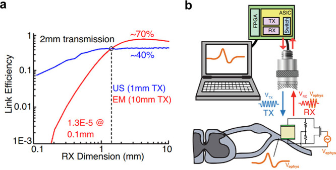
Operating principles for neural dust. (a) Link efficiency for ultrasound (US) and electromagnetic (EM) coupling through biological tissue versus dimension of the receiver (RX). Ultrasonic links outperform EM links below 1 mm. (b) Schematic for remote sensing of physiological action potentials. The local electric potential influences the backscattering signal of the piezo element. This information can be recovered remotely via ultrasonic imaging. Reproduced with permission from ref (160). Copyright 2018 Elsevier.
The concept of neural dust is explained by the schematic in Figure 12b. Each piezo crystal is connected to a compact electrical network including a field effect transistor (FET). The FET couples the electrical load impedance of the circuit to the surrounding electric potential, which affects the elastic behavior of the crystal. When ultrasound is focused onto the neural dust mote, the backscattered echo is modulated by the local electric field, revealing information about action potentials and enabling wireless probing of neuronal activity. By using ultrasound imaging transducers, electric states of dust motes in potentially many different places can be monitored in parallel. In vivo electromyograms and electroneurograms have been remotely recorded using a single mote implanted in a rat.162 The smallest mote to date has been reported by Shi et al.,163 which is capable of measuring temperature in just a 0.1 mm3 package. The authors demonstrated the device in vivo implanted in brain and muscle tissue of mice.163
Stim dust is complementary to neural dust, expanding the concept toward stimulation of nerves.164 Nerves and muscles can be excited remotely using the direct piezoelectric effect, which converts mechanical (acoustic) energy into electrical energy. A major hurdle, however, is to provide a controlled current output via the remote power link. On the one hand, high-frequency acoustic waves (typically megahertz) should be used in order to focus all of the energy efficiently into a small region around the sub-millimeter-scale device. On the other hand, nerves respond to transient action potentials with millisecond time scales, which would be better driven by low-kilohertz acoustic waves. To bridge the temporal gap between the ultrasonic and biological worlds, Piech et al.164 showed that electronic rectifying circuits can be used, converting the megahertz-frequency ultrasonic energy into lower-frequency signals for nerve stimulation. The authors successfully combined a piezoceramic element, energy-storage capacitor, and integrated circuit into a 1.7 mm3 small device and demonstrated it in vivo mounted on the sciatic nerve of anesthesized rats. The device was capable of delivering 50–400 μA pulse amplitudes, pulse widths of up to 392 μs, and pulse repetition frequencies up to 5 kHz. This was sufficient to excite compound action potentials and cause twitches in the rat’s muscles. In these experiments the ultrasound field had a derated ISPPA = 692 mW cm–2 and a mechanical index MI = 0.11, both below the safety limits set by the FDA.56
All of these devices use active elements made of lead-based piezoceramics, which are toxic to humans and thus limit biocompatibility. To realize the potential of implantable sensing and stimulation devices, more work is needed to improve the efficiency of biocompatible piezo materials.
3.3.3. In Vivo Sensing of Biomolecular and Cellular Processes
In vivo imaging techniques to monitor biological and cellular processes are highly desirable but challenging to realize. Established optical methods for noninvasive imaging of biological tissues are limited to low penetration depths due to strong scattering. In contrast, the low attenuation of ultrasound gives it an advantage to visualize biomolecular events in vivo.
Ultrasound molecular imaging can be achieved by monitoring the change in ultrasound scattering intensity by microbubbles that are injected intravenously.165 The concept is based on engineered microbubbles, whose lipid shell is covered with ligands that can selectively bind to cells on the surface of blood vessels.54 The microbubbles have a typical size of 1–10 μm, which permits circulation throughout the vasculature and enables targeting regions inside capillaries (diameter < 10 μm). This size range also provides good acoustic contrast, as is also exploited in microbubbles as commercial ultrasonic contrast agents. The use of smaller bubbles to probe extravascular structures has not been fully explored, hampered by their much weaker scattering response at the relevant medical ultrasonic frequencies.54 Recent developments, however, show promise to extend ultrasound molecular imaging to smaller bubble sizes. For instance, Jafari Sojahrood et al.166 reported fabrication of shell-stabilized nanobubbles with a precisely controllable acoustic response. It has been shown that the scattering response of encapsulated microbubbles behaves nonlinearly and is strongly amplified beyond a threshold excitation pressure pt. This threshold depends on the elastic properties of the shell and can be tuned to maximize signal response with minimal bubble collapse. In this study the authors used propylene glycol as a membrane softener or glycerol as a membrane stiffener and fabricated bubbles of 200 nm mean diameter and varying thresholds in the range 120–710 kPa.
An alternative to manufactured micro- or nanobubbles is gas vesicles. These are “gas-filled compartments with a protein-shell with typical widths of 45–250 nm and lengths of 100–600 nm.”167 Their shell consists of proteins known as Gvp proteins, with GvpA being the main constituent.168 The difference in hydrophobicity and hydrophilicity within the protein structure allows the permeation of gas while excluding liquid water. This enhances the stability of vesicles in comparison to an uncoated nanobubble, which quickly dissolves because of the high Laplace pressure.
Gas vesicles show promise as a tool for molecular imaging using ultrasound. Bourdeau et al.169 created a so-called acoustic reporter gene (ARG) that expresses the proteins necessary to stabilize the gas vesicles. As a proof of concept, the authors demonstrated the use of ARG to locate two different types of genetically engineered bacteria inside the gastrointestinal tract of a mouse.169 More recently it has been shown that ARGs can be used to sense enzyme activity in probiotic bacteria.170
Gas vesicles can be remotely observed with ultrasound scattering, as shown in Figure 13a. In general, gas vesicles give rise to a bright backscattered contrast (echogenicity) in ultrasound imaging. The scattered intensity depends on the gas vesicle size,169 which can be tailored by genetically engineering the coating protein composition,171 or by changing the bacterial species that produces the vesicles.167,169 In general, smaller gas vesicles exhibit low echogenicity.169 In addition to linear scattering, nonlinearly scattered signals can also be used to accurately localize gas vesicles.172,173 The nonlinear response also depends strongly on the strength and composition of the protein shell, which can be controlled by changing the producing species,167 or direct genetic engineering.171 For example, irradiated with 6 MHz pulses (peak amplitude 98 kPa) the gas vesicles produced by the microorganism Halobacterium NRC-1 produced second- and third-harmonic signals at 12 and 18 MHz, but vesicles produced in Anabaena flos-aquae did not.167
Figure 13.

(a) Sensing of gas vesicles inside the gastrointestinal (GI) tract of a mouse: expression of the acoustic reporter gene (ARG) in probiotic bacteria generates gas vesicles that show ultrasound contrast. (b) Ultrasound images of gel phantoms containing E. coli bacteria expressing arg1 before and after collapse of gas vesicles (scale bar 2 mm). (c) Transverse ultrasound image of a mouse colon containing E. coli bacteria expressing arg1 proximal to the colon wall (scale bar 2.5 mm). Panels b and c adapted with permission from ref (169). Copyright 2018 Springer Nature.
The hydrostatic collapse pressure of the vesicle structure can also be used to confirm the presence of distinct species by comparing images before and after collapse (see Figure 13b). Above a certain confining pressure, the protein shell of the vesicles buckles and the gas can diffuse away, eliminating any echogenicity. The critical hydrostatic collapse pressures range from 40 kPa to over 700 kPa depending on bacterial species.174,175 However, these values do not directly translate to acoustic collapse pressures. For example, Halobacterium salinarum collapsed at acoustic pressure amplitudes 9 times higher than the critical pressure observed under quasi-hydrostatic conditions.176 Since the collapse pressure is controlled by the vesicle protein composition, acoustic monitoring of collapse can be used to distinguish different vesicle-carrying species.167,169,171 Vesicles can therefore be differentiated based on absolute echogenicity differences (linear and nonlinear) or alternatively using the echogenicity difference before and after vesicle collapse. For ultrasonic observation of gas vesicles, the most critical factors are thus the size and protein composition of the stabilizing shell, both of which can be adjusted by appropriate species selection and genetic engineering.
The functionality of gas vesicles continues to grow due to continuing advances in genetic engineering. For example, by engineering the vesicle-producing ARG, the gas vesicles’ responsiveness to ultrasound can be tuned (e.g., the collapse pressure or the scattering strength).171 By using properly designed ARGs in one setting, the differences in acoustic response can be used to monitor multiple different biological processes simultaneously. Additionally, expressing the ARG in bacterial hosts can enable targeted cavitation of the gas vesicles. This has been shown to complement bacteriotherapy with high-intensity focused ultrasound (HIFU) as a theranostic approach to treat breast cancer. The ARG was expressed in E. coli, which specifically targeted and colonized the tumor site inhibiting the tumor growth. The gas vesicles further acted as nuclei for cavitation during HIFU ablation of the tumor.177
In the future it will be of interest to express ARGs not only in bacterial hosts, but also in mammalian cells, as was recently accomplished by Farhadi et al.178 However, the ARG currently requires much longer time to express the gas vesicles in mammalian hosts (days) than in bacterial host (hours). A review that explores further directions and perspectives of ultrasound technologies for neuroimaging and neuromodulation has been written by Rabut et al.179
3.4. Payload Transport and Delivery
3.4.1. Payload Transport and Release
Ultrasound can be used to control the spatial and temporal release of substances. Its tremendous potential for remote activation garnered with its biocompatibility and low attenuation in tissue has steadily motivated the field of smart drug delivery systems.55,180,181 The state of the art in ultrasound-triggered payload delivery is based on encapsulated microbubbles. Current efforts can be grouped into four broad classes, based on the specific carrier technologies that they use: microbubbles (section 3.4.1.1), phase-change nanodroplets (section 3.4.1.2), nanocarriers (section 3.4.1.3), and emerging carriers (section 3.4.1.4).
3.4.1.1. Microbubbles
Microbubbles play a central role in efforts to transport and release a chemical or nanoparticle payload upon ultrasound exposure. Microbubbles have been studied for more than 30 years, initially as ultrasound contrast agents and more recently as targeted drug carriers operated using medically relevant ultrasound.54,55,180−185 This section aims to cover selected examples from this highly active research field, presenting case studies to illustrate possibilities and limitations when developing smart systems that require the transport and release of chemical payloads. Readers interested in the use of microbubbles as ultrasound contrast agents and as drug delivery vehicles should consult recent comprehensive reviews.54,55,181,183
When irradiated with ultrasound, bubbles display volumetric oscillations that are responsible for mechanical, thermal, and chemical effects.55 The extent of these effects is determined by the surrounding medium and the microbubble structure, namely the type of gas enclosed as well as the composition of the stabilizing shell. In the context of drug delivery, the shells are typically composed of lipids enclosing perfluorocarbon gas, which have low solubility in water. The payload can be included by dissolving it in an oil layer inside or within the shell, by electrostatic binding to the outer surface, or by directly linking the surface to molecules or nanocarriers,186 as illustrated in Figure 14a. Alternatively, shells can be made of proteins, surfactants, or polymers,187 while other gases such as oxygen can also be enclosed, although the stability becomes a challenge.
Figure 14.

Microbubbles can be used to transport and release a payload upon ultrasound exposure. (a) Scheme showing the different ways to accommodate the payload in the microbubble structure: (I) using an oil layer, (II) within the shell, (III) via electrostatic binding, and (IV) direct linkage to the surface. (b) Microbubble response to different ultrasound regimes.
Microbubbles can be used either directly as payload carriers or indirectly to enhance chemical transport, e.g., through cavitation induced sonoporation (see section 3.4.2). When microbubbles are used as carriers, an acoustic pressure beyond a critical amplitude leads to rupture and release of the shell fragments,188 as shown in Figure 14b. By this method the payload can travel hundreds of micrometers in vivo(189) and millimeters in gel media.190 The detailed mechanism of this delivery mechanism is not yet fully understood. For a recent review covering control of cavitation for drug delivery, see ref (55). For indirect delivery techniques, irradiating cells with low-intensity ultrasound in the presence of exogenous microbubbles has been shown to enhance permeation into the cells.191,192
Microbubbles have been studied for targeted delivery of chemotherapy drugs,193,194 for gene delivery,195,196 and to open the blood–brain barrier.197,198 Extension of microbubble techniques and functionalities in different contexts has also revealed application-specific limitations. For example, to treat hypoxic tumors microbubbles carrying oxygen are preferred, but their low lifetime leads to a short circulation (<5 min) and hence low targeting efficiency when administered systemically.199 To overcome this limitation, different targeting techniques can be employed. For instance, microbubbles can be covered with ligands that specifically bind to a target site. The targeting in this case can be further enhanced by using acoustic radiation force to increase the microbubble concentration near the target.200 Alternately, the microbubble shell can be functionalized with superparamagnetic iron oxide nanoparticles and aggregated at the target site using magnetic fields.193,201,202 One study used a combination of magnetic and acoustic fields,193 which were realized with a focused ultrasound transducer and a permanent magnet combined in a single device. The fixed alignment made it possible to aggregate and excite microbubbles with intense ultrasound (1 MHz, 3 W cm–2) and keep them in focus. The authors found a significantly enhanced reduction in tumor size within the first 8 days that was not observed using only one of the two fields independently.193
Microbubbles can also be used to disperse nanoparticles in complex media. Recently, Baresch and Garbin203 trapped nanoparticle-coated microbubbles with an acoustic vortex beam and released the nanoparticles using ultrasonic excitation from a second transducer. The experiments were conducted in agarose (shear modulus G ≈ 10 kPa). For bubbles excited close to resonance, large-amplitude nonspherical oscillations caused the particles to eject in multiple directions as plumes, propelling them multiple bubble diameters into the gel.
While microbubbles form the basis for many techniques in payload delivery, their size imposes difficulties in their use, especially in vivo. On the one hand, micrometer-scale gas bubbles are difficult to stabilize against diffusion, especially in the presence of ultrasound. On the other hand, micrometer-scale bubbles are too large to permeate into smaller areas of interest including extravascular structures such as tumors.204
3.4.1.2. Phase-Change Nanodroplets
To address the current challenges of microbubbles, phase-change nanodroplets have emerged as alternative carriers and have been developed for improved stability, longevity, and extravasation.206 Nanodroplets are vesicles that contain a core of phase-changeable material and that can be decorated with functional drugs.207 Their size range (400–800 nm)206 is comparable to the gap between endothelial cells (380–780 nm),208 which can enhance uptake of drugs due to improved extravasation into tumor tissues (Figure 15a). Commonly used materials for the core are perfluorocarbons (PFCs), because they are nontoxic and have low solubility in water, improving the lifetime of the droplets.209,210 PFCs are volatile compounds: for example, the boiling temperature Tb of perfluoropentane (PFP) is 29 °C and that of perfluorohexane (PFH) is 56 °C.211 Thus, when the liquid droplet is exposed to physiological temperatures, it becomes metastable and readily transitions to the gas phase upon excitation with ultrasound.212 This process, known as acoustic droplet vaporization (ADV),213,214 causes a dramatic change in size. Depending on composition, nanosized liquid droplets with diameters of 200–300 nm can expand into 1–5 μm gas bubbles.205,215 The evolution of growing PFC gas bubbles after acoustic vaporization is shown in Figure 15b. While the nano liquid droplets provide transport stability in a small-scale carrier, the expansion process can be used for mechanical agitation and stronger ultrasonic contrast. These characteristics benefit diagnostic and therapeutic uses such as ultrasound imaging,216−218 drug delivery,219−221 BBB opening,222 and sonothrombolysis.205,223,224
Figure 15.

(a) Illustration of drug delivery through an extravascular barrier using phase-changeable nanodroplets. (b) Time-resolved microscope images of PFC nanodroplets before and after ultrasound exposure. Scale bar 50 μm. Reproduced from ref (205). Copyright 2019 American Chemical Society.
While most demonstrations using PFC droplets have required high-intensity ultrasound, the nanodroplet design can be modified to trigger phase change at lower intensities. The use of materials with low boiling points (e.g., decafluorobutane (DFB), Tb ≈ −1.7 °C)215 is one approach to reduce the vaporization threshold intensity,207,225,226 approaching the safety limits for clinical ultrasound (see section 2.3.5). The vaporization threshold is further influenced by surface tension and droplet size.227,228
Different techniques have emerged for multistage payload release using PFC nanodroplets. Cao et al.229 demonstrated that different release stages could be triggered at different ultrasound intensities by properly designing the nanobubble shell. They produced two different droplets made of different shell materials: either lipid based (softer) or PLGA based (harder). The droplets could be vaporized with 1 MHz ultrasound at electrical driving powers of 3 and 8 W, respectively. The treatment then proceeded in two stages. First, the soft-shelled nanodroplets generated small pores, which enabled the hard-shelled droplets to diffuse deeper into the tissue before being vaporized and releasing the drug doxorubicin.229 Aliabouzar et al.230 demonstrated that nanodroplets made with different PFC cores could be triggered at different frequencies. They created two kinds of nanodrops containing either perfluorohexane or perfluorooctane along with a molecular payload. While both droplet types could be vaporized at 2.5 MHz, only the perfluorohexane droplets vaporized at 8.6 MHz, allowing them to be activated first using the high-frequency excitation.
Acoustic droplet vaporization can also be used as a microscale ballistic tool to propel particles, a concept which has been demonstrated by Soto et al.231 Hollow tubes were filled with silica microspheres (diameter 1 μm) or fluorescent polystyrene spheres (diameter 100 nm) as well as PFC embedded in a gel matrix stabilizer. An acoustic pulse triggered vaporization of the PFC, ejecting the particles. The nanoparticles were found to travel 17.5 μm into a gelatin phantom.
Phase-change nanodroplets show enhanced performances over microbubbles for payload delivery through small regions. However, the triggering thresholds of nanodroplets are based on a complex interplay of composition and ultrasound parameters, and the resulting effects of vaporization at the target site are not yet fully understood. For future clinical applications it is important to predict and control the behavior of ultrasound on the vaporization and its effect in tissue.206
3.4.1.3. Nanocarriers
Nanocarriers present a third option for the ultrasound-triggered release of payloads.232 They comprise different inorganic and organic particles with sizes up to several hundred nanometers, and their size enables them to access hard-to-reach places.233
Most inorganic carriers can transport a payload either adsorbed or conjugated to the surface. Examples include mesoporous silica particles (MSNPs), gold nanoparticles, superparamagnetic iron oxide nanoparticles (SPIONs), and carbon nanotubes (CNT).185 When irradiated with low-frequency ultrasound (20–90 kHz), the payload is irreversibly detached by a cavitation process, as shown in Figure 16a. Cavitation is caused by nucleating freely dissolved gas or interfacial gaseous voids located on the rough surface of the particles.234 MSNPs and CNTs can also be used as air-containing nanocarriers.235,236 The high hydrophobicity of CNTs allows them to retain air stably inside their hollow structure, which can be used to enhance cavitation or as contrast by reflecting for high-frequency ultrasound.237 Cavitation effects can be further enhanced with external stimulation. For example, it has been shown that irradiating gold nanoparticles with intense light pulses generates bubbles whose presence lowers the ultrasonic pressure threshold for cavitation.234,238
Figure 16.

Mechanism for payload release of nanocarriers. (a) Irreversible and (b) reversible releases of payload from nanocarriers. On the left in (a) and (b) are the initial states of the nanocarriers with the payload on the surface and encapsulated inside, respectively. Irradiation of the nanocarriers with ultrasound (20–90 kHz) induces cavitation, where the emitted shock wave and temperature increase (a) destroy the nanocarrier or (b) temporarily open the structure for the release of the payload.
In situations where surface conjugation is not straightforward, self-assembled organic nanocarriers such as liposomes, nanoemulsions, polymeric micelles, or polymersomes can be used to encapsulate the cargo within their structures. Unlike surface-loaded nanoparticles, their response to ultrasound depends on specific characteristics of the self-assembled structure. For example, the temperature increase caused by focused ultrasound (1.1 MHz) in hyperthermia treatment also enhances the permeability of liposomes and hence the release of a payload.239 Irradiation at lower frequencies but higher amplitudes generates shear stresses that can rupture vesicles. However, the ruptured liposomes will readily re-form multiple smaller vesicles with the same total surface area (assuming no loss of phospholipids).180,240 Hence, this mechanism involves a partial release of cargo from the liposomes.180 Similarly, polymersomes also show a size reduction proportional to the duration and power of the applied ultrasound (20–40 kHz, 0–180 W).241,242 In contrast, polymeric micelles temporarily release the payload when irradiated with low-frequency ultrasound (20–90 kHz), but then reencapsulate most of the cargo after the ultrasound exposure has stopped, suggesting a reversible release when compared with surface loaded nanocarriers, liposomes, and nanoemulsions (see Figure 16b).243 This behavior implies that polymeric micelles could be used for longer term applications that require release over multiple exposures to ultrasound.244 This so-called “reversible mechanism” for payload release requires higher power densities at higher frequencies.245 The onset of release occurs above a threshold ultrasound intensity (0.3 W cm–2 at 70 kHz)246 and pulse length (0.1 s at 20 kHz with intensity 58 mW cm–2).247 Recently, it has been proposed that the dominant factors in the ultrasound response of self-assembled structures are the solvent type and the temperature at which the structures are self-assembled.248 In this study, block copolymer micelles and vesicles (polymersomes) were irradiated with low-frequency ultrasound (20 kHz, 37.5 W, 3 min). Improved ultrasonic bursting and reassembly were observed when the temperature at which the polymer chains were self-assembled is close to the glass transition temperature of the hydrophobic segment. This principle was applied by the same authors to fabricate pH–ultrasound responsive polymersomes to release the chemotherapeutic drug doxorubicin. The polymersomes were designed to respond to the slightly more acidic pH of the tumor microenvironment by initiating the release with ultrasound irradiation (20 kHz, 45 W).242
At high frequencies, polymeric micelles irreversibly release payloads via bond breakage of ultrasound responsive groups within the structure of the amphiphilic units. This was demonstrated by using high-intensity focused ultrasound at frequencies close to 1 MHz.249,250 Bond breakage occurred at the labile bond sites, which are sensitive to thermal and mechanical effects induced by ultrasound (see section 3.5.2).
Many more options for ultrasound-responsive nanocarriers emerge from combinations of the examples above. The combination of liposomes with microbubbles is a common approach185 that has recently been used to trigger enzymatic gelation.252 The liposomes contained calcium ions that were ultrasonically released in the presence of the enzyme transglutaminase, forming fibrinogen hydrogels through covalent intermolecular cross-linking. A less common, yet interesting, example is the combination of MSNPs with ultrasound-sensitive block copolymers. For example, by grafting block copolymers with ultrasound sensitive bonds, similar to polymeric micelles, a gating effect over the pores of the MSNP can be used to trigger the release of a payload, as shown in Figure 17.251 This study used high-intensity focused ultrasound (HIFU; here 1.3 MHz, 100 W) to break labile bonds and switch the polymer chain to a hydrophobic state, where its structure is expanded, allowing the payload to be released. These examples demonstrated new ways to release payload from the nanocarriers. Many current systems rely on surface immobilization, which requires a surface chemistry that can couple the payload to the carrier. A solution to this problem can lie in supramolecular host–guest complexes, where the reversible binding may be disrupted by ultrasound,253,254 although the inclusion of the supramolecular host to the carrier might still be a challenge. Lastly, inorganic vesicles made of self-assembled Au–MnO Janus particles are an example of a new functionality established through the material selection of inorganic carriers. These vesicles disassemble following ultrasound irradiation and permeate deep through liver tumors to generate radical oxygen species after glutathione triggered MnO degradation.255
Figure 17.

(a) Plot of the release of fluorescein in solution from a mesoporous silica nanoparticle (MSNP) grafted with a HIFU sensitive block copolymer (10 min and 1.3 MHz, 100 W). (b, c) Fluorescence microscopic images of cells incubated with rhodamine B labeled MSNPs–polymer with fluorescein shown respectively before and after ultrasound exposure. Adapted from ref (251). Copyright 2015 American Chemical Society.
3.4.1.4. Emerging Carriers
Emerging carriers are providing promising new directions and capabilities for payload delivery. Although these techniques are still in their infancy, we summarize this early work here to provide insight into new directions for the field.
An alternative carrier to conventional microbubbles has recently emerged in the form of Pickering-stabilized antibubbles.256,257 Antibubbles consist of a liquid core surrounded by a thin gas layer that separates the core from the surrounding fluid. Recently it has been shown that the liquid core causes antibubbles to oscillate asymmetrically, which gives rise to higher harmonics with nonlinear scattering strengths comparable to or higher than those for conventional microbubble contrast agents.258,259 The nonlinear radius oscillations may also provide a mechanism to more easily burst the antibubble and deliver a payload from the core, avoiding the surface modifications required by microbubble techniques. Further functionalities can be added to antibubbles by appropriate payload selection. For instance, magnetically responsive antibubbles were produced by dispersing Fe3O4 particles in the liquid core.260 While still an emerging topic, antibubbles offer new potential pathways to realize ultrasound triggered payload release.
In contrast to microbubble- and nanocarrier-based systems, hydrogel carriers enable the stepwise release of a payload. Most of the systems mentioned above only permit one time release triggered by ultrasound or the gradual release over longer time periods. However, there are scenarios in which it is desirable to release the payload over multiple large doses at arbitrary times. Such systems have been described as permitting digital drug release.261,262 This concept has been demonstrated using hydrogels.261−268 Huebsch et al.261 studied biocompatible injectable alginate hydrogels for on-demand release of the chemotherapeutic drug mitoxantrone. They showed that ultrasound pulses (20 kHz, 9.6 mW cm–2, pulse length 5 min, pulse repetition frequency (PRF) 1 h–1) disrupt the ionically cross-linked polymer network, releasing the mitoxantron. Once the ultrasound stops, the self-healing of the hydrogel prohibits a further release of the chemotherapeutic. Recently, it has been shown that ultrasonic exposures needed to generate significant therapeutic deliveries from calcium-cross-linked hydrogels also generated high levels of gel heating and erosion—an effect that can be mitigated with pulsed ultrasound.267
3.4.2. Opening Biological Barriers
Ultrasound can open biological barriers (e.g., cell, blood–brain) and make them more permeable for the delivery of therapeutic payloads.
Sonoporation (the opening of the cell membrane with ultrasound) is triggered by cavitation and associated bubble-driven streaming in the vicinity of a cell membrane.269 The resulting large shear stresses deform the cells and form pores,270,271 which leads to endocytosis, opening the cell membrane such that molecules can passively diffuse into the cell272 (see Figure 18a). Similar effects have also been observed for enhancing delivery through skin.273,274 Sonoporation has been confirmed by real-time confocal microscopy that the ultrasound-stimulated bubble oscillation generates the shear stress above the threshold of pore formation on the cell membrane.275 Recently, sonoporation has also been demonstrated at cell–cell contacts.276 The cell membrane opening can be temporary or permanent. The size of pores formed in the membrane depends on the ultrasound intensity, because of the larger cavitational shear stresses as shown in Figure 18b,c.277 Large carriers, such as nanoparticles or larger macromolecules, require higher ultrasound intensities compared to small molecules to permeate through the same membrane. Acoustic pressures of 190–480 kPa created pores in the size range 1 nm–4.3 μm, and for pressure amplitudes below 250 kPa the (MCF7) cells could self-heal their cell membranes.278 Several studies confirmed the correlation between pressure and pore size by measuring the corresponding uptake efficiency279 and molecular diffusion.280 Qiu et al.277 showed enhanced transfection of DNA mixed with polyethylenimine (PEI) into cells when exposed to ultrasound in the presence of microbubbles (44.7%) compared to without microbubbles (10.8%) in vitro. The enhanced uptake of drugs via sonoporation has been demonstrated for different kinds of substances from nanoparticles to DNA,182,281−283 although most of the studies have been performed in vitro with limited validation in vivo.282
Figure 18.

(a) Mechanism of sonoporation by ultrasound-induced microbubble cavitation ((I–III) stable cavitation-induced sonoporation; (IV, V) inertial cavitation-induced sonoporation). Adapted with permission from ref (269). Copyright 2014 Elsevier. (b) Cellular uptake of transferrin and fluorescent dextrans of different molecular weights (4.4 and 500 kDa) by endocytosis (no depletion) and diffusional process (ATP depletion) under ultrasonic radiation for 30 s (1 MHz ultrasound, 20 Hz pulse repetition rate, 0.22 MPa peak negative pressure). Reproduced with permission from ref (272). Copyright 2009 Wolters Kluwer Health. (c) Pore size created by sonoporation as a function of ultrasound pressure. Reproduced with permission from ref (277). Copyright 2010 Elsevier. (d) Focused ultrasound induced microbubble cavitation, locally opening the blood–brain barrier for drug transmission. Cavitation can be monitored by an acoustic detector and applied with closed-loop control. Reproduced from ref (284). CC BY 4.0. (e) The nanobubbles can be labeled with paramagnetic particles, enabling a magnetically guided blood–brain barrier opening process. Reproduced with permission from ref (290). Copyright 2014 John Wiley and Sons. (f) In vivo bioluminescent imaging verifies the ultrasound activated microbubbles enhancing gene delivery across the blood–brain barrier. LpDNA, liposome-containing pDNA, MBs, microbubbles, FUS, focused ultrasound. Reproduced with permission from ref (289). Copyright 2016 Elsevier.
In addition to cell membrane sonoporation, microbubble cavitation also improves drug delivery across other biological barriers, such as the blood–brain barrier (BBB) (Figure 18) and blood–spinal cord barrier.284−286 These barriers prevent solutes in the circulating blood from nonselectively crossing into extracellular fluid of the central nervous system where neurons reside and, hence, also prevent drug delivery to the nervous system. Similar to bubble-based cell membrane sonoporation, ultrasound-activated microbubbles can open these barriers via inertial and stable cavitation. The latter happens when the bubble size is similar to the blood capillary diameter. The bubble should be in contact with the capillary wall for efficient permeation.287 Depending on the microbubble size and the applied acoustic pressure, the BBB opening can be permanent or reversible. In one study BBB was shown to recover between 24 h for 1–2 μm sized bubbles driven at 0.45 MPa acoustic pressure and 5 days for 6–8 μm sized bubbles driven at 0.6 MPa acoustic pressure.288 Drugs can also be conjugated to the microbubbles to enhance the efficacy of delivery. Lin et al.289 demonstrated a gene delivery strategy via ultrasound-activated microbubbles conjugated with gene-loaded liposomes in a Parkinson’s disease mouse model. Huang et al.290 embedded superparamagnetic iron oxide nanoparticles on the microbubbles, which allowed magnetic guidance of the bubbles toward a specific brain region coupled to ultrasonic opening of the BBB. Beyond blood barriers, Schoellhammer et al.291 demonstrated that ultrasound could enhance drug delivery through the gastrointestinal tract, based on inertial cavitation.
Nanodroplets can also be used for delivery through the BBB. Chen et al.222 found that nanodroplets achieved a similar performance in transporting dextran across the BBB compared to microbubbles above a pressure of 0.60 MPa in a mouse model. Samples treated by nanodroplets showed no tissue damage, whereas the bubble-treated samples showed minor damage. Using nanodroplets, the BBB could be opened using pressures of 0.45–0.60 MPa (at 1.5 MHz and PRF 5 Hz).
The studies above demonstrate that ultrasonically activated microbubbles and nanodroplets are promising tools for opening biological barriers. Further research on a region-selective or disease-related BBB opening can be expected to explore conjugating the carriers with specific biomarkers and to expand testing with in vivo models.
3.5. Initiating Biological and Chemical Processes
Ultrasound can be used to deliver a chemical payload, but in some cases, it may be preferable to directly trigger a chemical reaction or a molecular change with ultrasound. Sonochemistry is a field that has long studied chemical effects caused by ultrasound.52,292 The traditional approach to sonochemistry utilizes high-power ultrasound to generate high pressures and temperatures that can trigger chemical processes in a bulk reactor. Recently, however, new techniques have begun to emerge that can provide control over molecular and chemical processes with much higher specificity and lower powers, making them relevant to a wider range of systems. Ultrasound can be used to generate reactive chemical species, break labile macromolecular bonds, stimulate protein complexes, or generate electric potentials to start electrochemical processes. When these processes are combined with emerging techniques such as nanocarriers, genetic engineering, or synthetic chemistry, they provide the possibility to create new kinds of systems driven directly by ultrasound.
3.5.1. Chemical and Mechanobiological Triggers
3.5.1.1. Sonosensitizers
Reactive oxygen species (ROS) play an important role in many chemical reactions, especially in biological systems. They are mostly known because of their deleterious effects on cells. Sonodynamic therapy (SDT) has been developing techniques that use ultrasound to control the production of ROS as a treatment for solid tumors.201,293 SDT is based on the use of a nontoxic sonosensitizer drug, which generates cytotoxic ROS when exposed to ultrasound in the presence of oxygen.193,201,294 Sonosensitizers consist of molecules295,296 or nanoparticles297,298 that are activated by low-intensity ultrasound201 (1 MHz, <4 W cm–2). The activation of molecules with ultrasound has been studied for more than 30 years,188 while the activation of nanoparticles dates back 10 years.299 More recently, improvements in SDT have been achieved by combining sonosensitive molecules with micelles300 or microbubbles.199,201,294,301 Many of the molecular sonosensitizers are also photosensitizers, which are used in photodynamic therapy where light is used to activate and generate ROS to destroy tumors.302 However, in contrast to photodynamic therapy, the mechanism of activation in sonodynamic therapy is not fully understood. Recently, it was proposed that the activation of the sonosensitizing molecules may proceed via sonoluminescence following the violent collapse of cavitating microbubbles in the ultrasound field (1 MHz center frequency, 3.5 W cm–2)294 (see Figure 19a). The activation mechanism for nanoparticles, however, might be different. Here it is important to distinguish between nanocarriers loaded with sonosensitizing molecules and nanoparticles used directly as sensitizers. While the loaded nanocarriers can be activated like molecular sensitizers, the nanoparticle sensitizers are activated by cavitation generated on the surface of the nanoparticle. In this case, it has been proposed that the inertial cavitation of these nanobubbles is responsible for the formation of the reactive oxygen species303 (see Figure 19b). Examples of nanoparticle sensitizers include superparamagnetic iron oxide nanoparticles (SPIONs), which also provide the possibility of combining ultrasound with magnetic fields for more accurate positioning. When irradiated with ultrasound (1 MHz, 1 W cm–2), they generate reactive oxygen species.297 More recently, mesoporous silica nanoparticles (MSNPs) were combined with titania and loaded with perfluorohexane to enhance cavitation when the perfluorohexane is vaporized under low-frequency ultrasound irradiation.298 More details on sonodynamic therapy can be found in recent reviews.293,303,304
Figure 19.
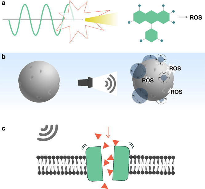
Ultrasound can be used to directly trigger or initiate (a, b) chemical and (c) biological processes. (a) Activation of molecular sonosensitizers to produce reactive oxygen species (ROS) via sonoluminiscence. (b) Production of ROS on the surface of inorganic particles via cavitation of nanobubbles. (c) Stimulation of mechanosensitive proteins using the acoustic radiation force.
3.5.1.2. Mechanosensitive Proteins
Ultrasound can also be used to directly control the behavior of biological systems. The most prominent example is in the activation of mechanosensitive proteins. Ion transport between cells and neuronal activity are triggered by membrane proteins that can open to allow ion flow upon external stimulation (see Figure 19c). Channels with mechanosensitive proteins (MS channels) sense and respond to external mechanical forces, such as shear forces, or internal ones, such as osmotic pressure or membrane deformation.305 In the case of neurons, ultrasound has been shown to induce a mechanical stress, modulating neuronal activity. This phenomenon has been studied for some time within the context of ultrasound neural modulation (UNM),306−311 yet recently a new approach that combines genetic engineering with UNM has opened new possibilities to control cell function in organisms using ultrasound.307,311,312 This approach, known as sonogenetics, is an acoustic analogue of optogenetics and chemogenetics, where cellular function is controlled using light and chemical signals, respectively. Sonogenetics, however, has the unique potential of not requiring light or the diffusion of drugs throughout the body, since, unlike light and small molecules, ultrasound can readily penetrate deep into tissue.
Sonogenetic techniques were first demonstrated by Ibsen et al.,312 who showed that locomotion of the worm Caenorhabditis elegans could be reversed in the presence of ultrasound-driven microbubbles. This behavior was triggered by 2.25 MHz ultrasound pulses (10 ms duration) with peak negative pressures between 0 and 0.9 MPa, but only when microbubbles were present. The authors attributed this behavior to the stimulation of mechanosensitive channels by microbubble cavitation. To confirm this, they showed that by genetically engineering the worms to misexpress the protein Trp-4, which is a pore-forming subunit of a mechanotransduction channel, the worms were much less responsive to ultrasound.
Subsequent works have extended the use of ultrasound-stimulated mechanosensitive channels to other research areas.313−326 Besides studying behavioral changes in living organisms,307,312,320,322−324 sonogenetics has also been used to trigger a cellular response against tumor cells.318,319,322,326 For example, when T cells were engineered to express the MS channel Piezo1, ultrasound excitation in the presence of microbubbles triggered the expression of the chimeric antigen receptor (CAR), which could detect specific tumor-associated antigens.319
Despite MS channels being widely expressed in cells, only a few types are useful to sonogenetics. These are Piezo1, MEC-4, Trp-4, hsTRPA1, MscL, Nav, Cav, and the K2p family. The K2p family of MS channels is the only one that is inhibited by ultrasound exposure, whereas the other channel types are activated by ultrasound.311 The mechanism is not fully understood and remains a matter of active discussion. The most accepted potential mechanism is that ultrasound induces conformational changes on mechanosensitive (MS) ion channels, opening pores that allow the transit of ions across the membrane307,311,327 (see Figure 19c). Channel stimulation can be achieved either by locally induced thermal changes323,328 (thermosonogenetics) or by ultrasound-induced shear stresses (mechanosonogenetics),329 although it is not clear which one is more important. The shear stresses can be amplified by microbubble oscillations during cavitation312,324,326 or by fluid streaming.307,317,325 A major difference between the thermal and mechanical mechanisms is their activation time scale. While thermal activation takes place over seconds, mechanical activation can trigger responses within milliseconds.307
The growing interest in sonogenetics suggests that ongoing developments will significantly enhance the capabilities of this technique in the near future. A key goal is to unravel the precise mechanism that underlies ultrasonic neural modulation and the ultrasonic activation of MS channels. Additionally, the translation of sonogenetics to in vivo applications can be facilitated by developments in smart targeting methods for cavitation near the desired target, such as acoustic reporter genes (see section 3.3.3) or phase-change nanodroplets (see section 3.4.1.2). Sonogenetics will further benefit from progress in synthetic biology, which could enable applications such as control over microbe proliferation in the gut or enable control over cell growth and expression of functional payloads in vivo.307
3.5.2. Mechanochemistry
While cavitation-based ultrasonics has led to sonochemistry, where chemical reactions are triggered with the generation of radicals and heat,292 recent work has shown that it is also possible to trigger reactions by changing the mechanical conformation of molecules. This field of research is known as mechanochemistry.332,333 Mechanochemical reactions are activated by bond breaking due to mechanical stimuli.334 Traditional mechanochemical reactions involve processes such as milling, grinding, or scratching in the solid state. In contrast, ultrasound makes it possible to trigger mechanochemical effects with ultrasound in solution.
Ultrasonic mechanochemistry makes use of molecules with an ultrasound-responsive bond, called mechanophores, that selectively break or change at predesignated sites during ultrasound exposure.335 The mechanophores break from shear stresses that result from unstable cavitation: bubble collapse during unstable cavitation generates large local fluid flows and intense shear stresses, which can physically stretch long molecules to break a chain (see Figure 20a). Since cavitation is required to trigger the reaction, the frequency and intensity of ultrasound used for these reactions are similar to traditional sonochemistry: the reactants are exposed for multiple hours to continuous-wave ultrasound between 20 kHz and 2 MHz,336 with average intensity levels of at least 3 W cm–2.337 Unlike conventional sonochemistry, however, a high level of specificity and control over the reaction is provided by the molecular design of mechanophores.
Figure 20.

(a) Schematic illustration of ultrasound-induced mechanochemistry using cavitation. Reproduced with permission from ref (330). Copyright 2012 John Wiley and Sons. (b) Reversible assembly and disassembly of Au nanoparticle aggregates bound by a split aptamer. Disassembly took place after 15 s using 20 kHz pulses, while recovery took 30 min. Aggregate structures were tracked by using UV–vis spectroscopy (left) and TEM (right). Scale bar 100 nm. Reproduced with permission from ref (331). Copyright 2021 John Wiley and Sons.
By tuning the properties of the mechanophore such as the strength and configuration of a labile bond, or the molecular weight of a chain that is activated, reactions can be triggered at precise locations and ultrasound intensities. Common mechanophore designs use a labile bond centered between large molecular chains to help break the bond via shear.338 Depending on the strength339 and configuration330 of the labile bonds, the mechanical force required to trigger the reaction and hence the required ultrasonic intensity are given.340 The molecular weight of the chain also determines the necessary ultrasonic energy: larger molecules require lower ultrasound intensity to break.341
The versatility and tunability of ultrasonic mechanochemistry have made it attractive for diverse applications, leading to an emergence of many new mechanophore designs and applications. By providing site-specific reactions, ultrasonic mechanochemistry has been attractive for broad applications in polymer chemistry, ranging from treating organic and inorganic compounds342 to self-healing components.343 Hu et al.344 developed a mechanically triggered cascade reaction that requires relatively low activation energies. This approach allowed the reaction to be triggered at room temperature and without large thermal changes to the surrounding media, which is a prerequisite for applications to temperature-sensitive biological systems. Recently, Zhou et al.345 demonstrated ultrasound-switchable protein activity based on a mechanophore coupled to green fluorescent protein (GFP). They applied ultrasound at 20 kHz with an intensity of 7 W cm–2 which stretched the protein, altering its folding stability and thereby its fluorescence brightness. Partial reversibility of the mechanism could be demonstrated. By changing the contour length of the linker structure attached to the protein (GFP-E36 to GFP-E72), they demonstrated the capability to tune the sensitivity of the protein response to ultrasound. Shi et al.346 showed that ultrasound could be used to simultaneously activate theranostic drug molecules and a fluorescent reporter. They designed bifunctional mechanophores composed of a disulfide bond, which was cleaved by pulsed sonication at 20 kHz with 15.84 W cm–2, activating the two molecules.346
One of the challenges in mechanochemistry is the high power levels and low frequencies (compared to clinical ultrasound), introducing potential risks for application in vivo. To overcome this challenge, noncovalent mechanophores have shown promise as a technique to reduce the activation energy and thus the ultrasound power. Zhao et al.331 used a split aptamer that interacts via hydrogen bonds and hydrophobic forces to trigger controlled release and to activate a thrombin catalyst upon ultrasound exposure. This process proceeded through the reversible disassembly of gold (Au) nanoparticles bound by the aptamer, as depicted in Figure 20b.331 Under focused ultrasound at 5 MHz (MI = 0.38), they achieved 75% of catalytic activity in 6 min. Although 20 kHz ultrasound with 10 W cm–2 can reach 50% of the activity in 15 s, these results showed reasonable effect strengths at clinical frequencies.
Ultrasonic mechanochemistry benefits from the ability of ultrasound to penetrate deeply into materials and the selective activation of different sized molecules using mechanophores. However, the technique requires an application-specific mechanophore design and high-power ultrasound to reach high reaction efficiencies.347 Of particular interest would be the development of universal mechanophores that can be controllably activated by low-intensity ultrasound.
3.5.3. Piezoelectrochemistry
Piezoelectric materials, which generate a voltage in response to mechanical stress,348 are inherently responsive materials. When exposed to an ultrasonic field, piezoelectric materials can be used to trigger electrochemical reactions or to trigger a neuronal response with electric fields, and thus they have gradually emerged as materials for ultrasonically controlled chemical reactions or medical therapies.349−351
When an insulating piezoelectric particle suspended in a liquid is exposed to an ultrasonic field, the ultrasonic vibrations will induce an oscillating electric polarization due to the piezoelectric effect. The associated electric field causes an energy shift of the valence and conduction bands throughout the piezoelectric material. When the energy shift is comparable to the difference in energies of the lowest unoccupied molecular orbital (LUMO) and highest occupied molecular orbital (HOMO) of a molecule in solution, eletctron transfer between the piezoelectric material and the species in the solution becomes possible, thus triggering a chemical reaction (Figure 21a).
Figure 21.

Piezoelectric materials for ultrasound-actuated electrochemical reactions. (a) Schematic for a piezoelectricity-induced chemical reaction: strain in the piezoelectric material generates electrical charges that change the energy state across the material, facilitating electron transfer between the material and the surrounding solution. Adapted with permission from ref (351). Copyright 2015 Elsevier. (b) Result of ultrasound-induced hydrogen production and its correspondence to the presence of piezoelectric material and the applied acoustic power. Adapted with permission from ref (352). Copyright 2019 John Wiley and Sons. (c) Photograph of ultrasound-actuated dye degradation and the experimental evaluation before and after the ultrasonic excitation. Adapted from ref (353). Copyright 2019 American Chemical Society. (d) Ultrasound-triggered generation of reactive oxygen species (ROS) and its application in tumor therapy. (insets) Digital photos of 4T1-tumor-bearing mice after treatment with ultrasound-activated BaTiO3 nanoparticles (right) and the control group without treatment (left). Adapted with permission from ref (354). Copyright 2020 John Wiley and Sons.
Piezoelectric particles have been developed for multiple applications of ultrasound-driven chemistry. One of the early applications was for hydrogen production via water splitting352,355,356 (Figure 21b) . Different piezoelectric particles have been used for this, including ZnO nanorods356 and BiFeO3 nanosheets.352 For example, You et al.352 achieved a 124.1 μmol g–1 hydrogen production rate with BiFeO3 nanosheets using 100 W of 45 kHz ultrasound applied for 1 h. In addition to hydrogen production, piezoelectric materials have also been used for dye degradation during wastewater treatment (Figure 21c).353,357 Wu et al.357 reported degradation of rhodamine B using ultrasound-actuated few-layer MoS2 nanoflowers. Compared to nonpiezoelectric control samples that used multilayer MoS2 or TiO2, the few-layer MoS2 particles with strong piezoelectricity showed a significantly faster degradation rate under the same ultrasonic conditions. The nanosized piezoelectric particles disperse well in wastewater; however, they are difficult to remove after the water treatment. To solve this issue, Qian et al.353 developed a composite ultrasound-responsive foam by mixing piezoelectric BaTiO3 microparticles with an elastomer, polydimethylsiloxane (PDMS). The porous foam can degrade the dye in solution actuated by ultrasound and can be more easily collected after the treatment.
Ultrasound-triggered piezoelectrochemical reactions can also be used to generate cytotoxic radicals, such as reactive oxygen species (ROS) for tumor therapy (Figure 21d). Zhu et al.354 reported ultrasound-triggered piezoelectric BaTiO3 nanoparticles for generating ROS for targeted tumor treatment. The piezoelectric nanoparticles were encapsulated in a hydrogel, and the composite was injected near the tumor. When exposed to ultrasound, the piezoelectrochemical reaction generated cytotoxic hydroxyl and superoxide radicals in the targeted region. In vivo experiments on mice verified that the therapeutic process was both effective and biocompatible. In addition to naturally occurring piezoelectric materials, Wang et al.358 also demonstrated that the inert poly(tetrafluoroethylene) can be ultrasonically activated to exhibit piezoelectricity and then applied for ROS generation.
In addition to inducing electrochemical reactions, the electrical charges generated by piezoelectric particles in an acoustic field can also be used for cell stimulation. Marino et al.359 demonstrated neural stimulation by ultrasonically activated piezoelectric BaTiO3 nanoparticles dispersed in cell culture media. Cellular responses such as calcium transients through the cell membrane were observed by fluorescence imaging of the ion dynamics after treatment by 1 MHz ultrasound and piezoelectric nanoparticles (Figure 22a,b). In another test of piezoelectric nanoparticles for cell stimulation,361 the electrophysiological response of a cell culture was measured with a microelectrode array patterned on the cell culture. The measurement showed that the combination of piezoelectric nanoparticles and ultrasound triggering could significantly increase neuronal activity (quantified by mean firing rate of the network of neurons). Finally, Marino et al.362 showed that piezoelectric BaTiO3 nanoparticles could be embedded into a 3D-printed microstructure for spatially resolved ultrasound stimulation of cells. Human sarcoma osteogenic cells were cultured on the microstructures, showing enhanced osteogenic differentiation (higher deposition of hydroxyapatite nodules) after ultrasound exposure compared to a control group without ultrasound exposure. Using a similar principle, enhanced cell differentiation in human neuroblastoma cells was observed on an ultrasound-activated piezoelectric film, which was made of poly(vinylidene fluoride–trifluoroethylene) and BaTiO3 nanoparticles360 (see Figure 22c).
Figure 22.

Piezoelectric materials for ultrasound-triggered cell stimulation. (a) Confocal fluorescence microscopy of piezoelectric BaTiO3 nanoparticles (red) attached to neuronal plasma membranes (green). (b) High-amplitude calcium ion transients (green curve) were observed with respect to an ultrasound (US) trigger (time point indicated by arrow) applied to the BaTiO3 nanoparticles (BTNPs). Panels a and b reproduced from ref (359). Copyright 2015 American Chemical Society. (c) Percentages of β3-tubulin positive cells (biomarker indicating differentiation) under different conditions verify the enhanced differentiation under synergistic action of ultrasound and piezoelectric nanoparticles. US–/+, ultrasound off/on; Control, without nanoparticles; P(VDF–TrFE), poly(vinylidene fluoride–trifluoroethylene); BTNPs, BaTiO3 nanoparticles. Reproduced with permission from ref (360). Copyright 2016 John Wiley and Sons.
3.6. Actuation and Locomotion
Ultrasound can be used to actuate smart systems. It can induce fluid flows or propel objects such as cells or micromotors through a liquid. Its biocompatibility and good transmission through tissue mean that ultrasound can induce motion in hard-to-access regions, which makes it promising for biomedical applications of smart devices.
3.6.1. Controlling Fluid Flow
Ultrasound can induce fluid streaming either in the path of the propagating waves or at oscillating fluid boundaries (as discussed in section 2.3.2). This has led to a number of applications of acoustic streaming in biology and for lab-on-a-chip devices which are discussed in this section. Early work on integrated devices focused on the use of surface acoustic wave (SAW) streaming effects, which were discovered by Shiokawa et al.363−365 and later developed by Wixforth et al.366−368 SAW techniques for fluid pumping and manipulation have been covered in recent comprehensive reviews on SAW microfluidics.6,14,369 Here, we focus primarily on acoustic-driven systems that utilize oscillating bubbles or solid structures to control the fluid flow or to manipulate micrometer to millimeter sized objects.
The role of streaming in controlling an object is governed by the object’s size. Bubble oscillations in an acoustic field produce an attractive radiation force on micrometer sized objects in the bubble’s near field. At the same time, the oscillating bubble generates streaming flows, which can exert a force on nearby objects via viscous drag in the fluid.370 Whereas the radiation force scales with the cube of the particle radius (FR ∝ R3), the streaming-induced force scales linearly with the particle radius (FS ∝ R).371 For example, for bubbles resonant on the order of hundreds of kilohertz, streaming is more effective for objects smaller than 10 μm whereas for larger objects the ARF becomes dominant.372,373 For objects tens of micrometers in size, acoustic forces in the range 1–10 nN can be generated by resonant microbubbles oscillating at tens of kilohertz, and streaming velocities at the bubble surface can reach values of 5–20 mm s–1 on resonance.373,374
Acoustic streaming flows can be used for different trapping and manipulation tasks at microscales. Micro objects can be trapped by localized streaming vortices, which are visualized in Figure 23a. For instance, Ahmed et al.375 captured and manipulated the nematode C. elegans in solution using arrays of acoustic-driven oscillating microbubbles in a microfluidic device. Acoustically-excited 250 μm bubbles at the hydrophobic walls of the device were used to trap the nematode via the acoustic radiation force, and the streaming flows caused its rotation. Further, Ahmed et al.375 demonstrated the in-plane and out-of-plane rotation of HeLa cells (Figure 23b,c) by simultaneous coupling of radiation force and acoustic microstreaming vortices for trapping and manipulation, respectively. Similarly, acoustic-streaming-based manipulation has been used to control other biosamples such as C. elegans,379 zebra fish,380 and pollen.381 Beyond simple manipulation, microstreaming flows generate shear stresses that can deform or even rupture small soft objects.40
Figure 23.

(a) Experimental demonstration of acoustic streaming during microbubble oscillation at 24 kHz (scale bar 30 μm). In-plane (b) and out-of-plane (c) rotation of a HeLa cell, driven by an oscillating microbubble at a constant frequency (scale bar 10 μm). Panels a–c reproduced from ref (375). CC BY 4.0. (d) Acoustic streaming vortices generated by oscillating sharp-edge structures rotate (e) a HeLa cell. Panels d and e adapted with permission from ref (376). Copyright 2016 John Wiley and Sons. (f) Structural design and configuration of the acoustics-based human microrobot interface platform (inset scale bar 10 mm) which includes a piezoelectric transducer (white), a glass substrate (yellow), a line-shaped micromanipulator (light blue), and a micro particle transported to the destinations (0, 1, 2, 3). (g) Schematic of particle transportation (right, scanning electron microscopic image of the microparticle, scale bar 10 μm)) and corresponding microscopic images (h) with a time lapse of 2 s (scale bar 50 μm). Panels f–h reproduced from ref (377). Copyright 2019 American Chemical Society. (i) Configuration of the acoustically driven bidirectional micropump. (j, k) Acoustic microstreaming flow induced by different sized bubbles. Panels i–k reproduced with permission from ref (378). Copyright 2020 Springer-Verlag GmbH.
Apart from bubbles, streaming flows can also be generated by oscillating microstructures. Hayakawa et al.382 used three (200 μm) micropillars arranged in a triangular configuration to generate circulating flows to transport and rotate mouse oocytes. Ozcelik et al.376 presented an on-chip acoustofluidic device that achieved rotation of single HeLa cells using steady streaming vortices (Figure 23d,e). Maximum flow rates on the order of 5 mm s–1 were predicted for the device, and rotation rates up to 60° s–1 were observed. These flows were generated by resonant oscillations of the micropillars at 5 kHz with an amplitude between 0.5 and 5 μm. The streaming effects induced by oscillating microstructures have also been used to transport particles.371,383 Lu et al.377 presented a user-controlled platform to manipulate microparticles with locally enhanced acoustic microstreaming along a fixed pathway (Figure 23f–h). By combining oscillating microstructures with viscoelastic fluid media, Zhou et al.384 showed that the streaming induced by vibrating micropillars can even be used to concentrate submicrometer particles.
Ultrasound-generated streaming flows can also be used to develop efficient pumps for lab-on-a-chip devices. Ryu et al.385 realized a microfluidic pump based on millimeter sized bubbles oscillating in water and achieved a flow rate of 0.6 μL s–1. Similarly, Gao et al.378 presented a bidirectional micropump by arranging different sized resonant microbubbles in a channel (Figure 23i). Because of the distinct resonant frequencies of the different bubbles, the flow direction could be controlled by switching the excitation frequency. The streaming flow pattern inside the channel around the different sized bubbles are shown in Figure 23j,k. Micromixers for lab-on-chip devices have been realized with microbubbles.386−390 Vibrating sharp-edge microstructures have also been utilized to build micropumps and micromixers in microfluidics. Huang et al.391 designed an acoustofluidic micromixer based on oscillating 250 μm sharp-edge structures excited at 4.5 kHz. With an identical working principle, Huang et al.392 created a programmable microfluidic pump by orienting an array of 20 sharp-edge structures 30° relative to the channel wall.
Viscous streaming flows have recently emerged as a powerful tool to generate flows in featureless small channels. For example, Huang et al.393 demonstrated that 100 MHz surface acoustic waves (SAW) could be used to drive viscous streaming flows within a lithium (Li) battery electrolyte. The induced flows minimized Li dendrite formation, increasing charging performance. By incorporating the SAW, they showed that it is possible to use lithium metal as an anode in a rechargeable battery for the first time.393 In an even more recent study, Zhang et al.394 identified a new nonlinear mechanism for SAW-driven streaming flows in nanoscale channels, which produced flow rates up to 6 mm s–1 in a 150-nm-tall nanoslit. These observed flow rates are more than 10 times higher, and the flow pressures more than 103 times higher, than those predicted by any other mechanism.394 This acoustogeometric streaming mechanism represents a unique new direction for applications requiring fast flows in nanoscale channels.
Ultrasonic streaming techniques present numerous advantages,395 including noncontact operation and suitability to manipulate cells and microorganisms.379 The devices are inherently compact, and operation at higher frequencies presents the opportunity for more compact integrated devices using SAW.6,369 These active acoustic systems can be incorporated into smart devices for noncontact fluid pumping, handling, and manipulation of objects.
3.6.2. Actuating Individual Particles and Swimmers
The emerging field of micro- and nanorobotics is especially receptive to smart materials because the small size of individual components prohibits the classic modular approach in macroscale robotics with onboard computation and memory. A review on smart materials for microscale robotics has been written by Soto et al.396 Ideally, the responsive behavior is encoded in the structure of the microrobot and can be controlled by an external field. Here, we focus on recent developments using acoustically initiated responses for propulsion and actuation in microsystems.
A major focus in microrobotic systems is controlled propulsion to a target area.401 Ideally, untethered actuation can be achieved in a variety of media, including biological ones, enabling minimally invasive medical interventions. A review by Nelson et al.402 presents the state of the art in medical microrobots and discusses potential applications. Several concepts for acoustically induced propulsion of microrobots have been proposed (Figure 24), based on forced body shape changes,397,403 asymmetric steady streaming,398,404−410 bubble streaming,370,399,411−413,413−419 or nonreversible jetting caused via rapid vaporization of a fuel.400 Note that some of the cited examples are not biocompatible, e.g., through incorporation of nickel or the addition of a catalytic motor based on decomposition of hydrogen peroxide, which prohibits use in vivo. However, the four acoustic actuation mechanisms described above are generally biocompatible and thus provide an advantage over other currently researched actuation concepts such as catalytic nanomotors.
Figure 24.

Acoustic microswimmer concepts. (a) Forced body oscillations. Adapted from ref (397). Copyright 2016 American Chemical Society. (b) Asymmetric steady streaming. Reproduced from ref (398). Copyright 2012 American Chemical Society. (c) Bubble streaming. Adapted from ref (399). CC BY-NC 4.0. (d) Acoustic droplet vaporization. Adapted with permission from ref (400). Copyright 2012 John Wiley and Sons. Detailed descriptions of subpanels are in the main text.
An artificial swimmer can for example use structural resonances of its body to propel itself forward (Figure 24a). Ahmed et al.397 presented such a swimmer fabricated by a template electrodeposition technique, which consists of a bimetallic head and a polypyrrole tail (Figure 24a1). The swimmer moved at velocities of up to 50 μm s–1 when driven at its fundamental resonance frequency of 91.5 kHz. Parts a2 and a3 of Figure 24 show the first bending modes and the flow developed around the swimmer at the first resonance, respectively. The swimmer motion relative to other tracer particles can be seen in Figure 24a4.
Asymmetric microswimmer design can also lead to fast self-propulsion in an acoustic field. Wang et al.398 investigated the behavior of metallic microrods in an ultrasound field, shown in Figure 24b. The microrods (2 μm length and 330 nm diameter) were first pushed toward the nodal plane of a standing acoustic wave (f = 3.7 MHz) inside a closed chamber (Figure 24b1), where they displayed linear motion and rotation (Figure 24b2). The rods’ fabrication process (template electrodeposition) resulted in asymmetric shapes with one end being flat (head) and the other end concave shaped (tail). The rods were made from a varying number of metals and always moved head first with speeds up to 200 μm s–1 (or 100 body lengths per second). This is surprising, since their size is much smaller than the corresponding acoustic wavelength (400 μm). The high speeds are thought to arise from asymmetric steady streaming, where an asymmetric particle oscillates in a uniform field (true in the pressure node for a particle with size a ≪ λ) and thereby induces a net flow.406 Many rods interacted and formed chains connected from head to tail, which then moved collectively in lines (Figure 24b3,b4) or circles (Figure 24b5,b6) around the nodal region.
Bubbles embedded in a microswimmer can also be used for propulsion. Figure 24c1 shows a bubble-based microswimmer described by Ren et al.399Figure 24c2 depicts the working principle, which is based on the primary and secondary Bjerknes forces FPB and FSB as well as the force caused by the bubble’s cavitation microstreaming, FSP. The authors found FPB ∝ ϵr3Pacf/cL and FSP ∝ ϵ2ρLr4f2, where ϵ is the amplitude of the bubble’s surface vibration, r is the bubble radius, Pac is the acoustic pressure, f is the acoustic frequency, and cL and ρL are the speed of sound and the density of water, respectively. For a 4 μm bubble driven at 1.33 MHz the authors find the streaming propulsive force to be 10 times stronger than the primary radiation force. However, the secondary radiation force attracts the bubble to a surface with FSB ∝ 1/d2, where d is the distance between the bubble and the surface. Close to a wall this causes the swimmer to approach it, rotate, and eventually point in the normal direction—which stalls its forward movement. To generate forward thrust, the authors aligned the nickel (Ni)-coated capsules with a magnetic field as shown in the right panel of Figure 24c2. The velocity could be set by changing the magnetic field direction. Even at a relatively low acoustic pressure of 4 kPa, the microswimmer was propelled at a speed of up to 2.5 mm s–1 (350 body lengths s–1) (Figure 24c3).
Acoustic droplet vaporization (see section 3.4.1) is another technique that has been used to propel a nanorocket (Figure 24d). Kagan et al.400 fabricated nanorockets in sizes ranging from 8 to 40 μm by stressed metallic (Au, Ni) thin film release or template electrodeposition. A crucial fabrication step was to functionalize the inner gold surface with cysteamine, which allowed a drop of perfluorohexane (PFH) emulsion to be trapped inside the cavity. Due to the slightly conical shape of the tube, the PFH was expelled via the larger opening once it had been vaporized by an acoustic pulse. A magnetic Ni layer permitted magnetic steering. When actuated, the rockets traveled at speeds over 6 m s–1. The authors demonstrated penetration 200 μm into tissue samples from a lamb kidney using pressure pulses ranging from 1.6 MPa over 44 μs to 3.8 MPa over 4.4 μs, without observing cavitation effects.
Bubble-based streaming actuators can be scaled up to generate larger forces or manipulate larger structures. Qiu et al.417 reported actuators that use large arrays of microbubbles. When remotely powered with ultrasound, the surface generated a propulsive force on the order of 1 mN. By combining multiple actuators with varying resonance frequencies between 20 and 100 kHz, a robotic arm could be actuated in multiple directions, where motion along each degree of freedom could be selected via the corresponding driving (resonance) frequency. The sound amplitudes required to operate the device were below 200 kPa.
Microrobots can themselves be seen as building blocks for smart materials, especially when they exhibit emergent collective behaviors.144 Ultrasound may induce collective effects directly through aggregation phenomena via the primary and secondary radiation forces.420,421 In addition, a combination of many interacting forces, such as magnetism and optical forces, can give rise to more complex behaviors.422,423 For example, Xu et al. demonstrated how the acoustic radiation force is about 8 times larger than chemical forces, but their interplay can be used to dynamically change the configuration of the micromotors.424
4. Conclusion and Outlook
Recent developments demonstrate the growing capabilities that ultrasound can provide to realize responsive systems. We have reviewed how ultrasound has been applied in diverse contexts to support smart capabilities. These can be grouped into six categories: directed assembly, modulation of material properties, sensing, payload transport and delivery, triggering of biochemical processes, and actuation and locomotion. These capabilities are enabled by several ultrasound mechanisms: cavitation, acoustic streaming, ultrasound-induced vibration, acoustic scattering, and acoustic radiation forces. By combining different mechanisms with creative system designs, unique capabilities have been realized for applications ranging from optical communication and imaging, to water treatment, to drug delivery and in vivo sensing of gene expression.
Moving forward, we expect to see a growth of applications for ultrasound-enhanced materials and microsystems. Emerging areas will also impose new constraints and demand more capabilities of their materials than the current systems do. We believe the demands of next-generation applications can be met in the short term by developments in three directions.
First, the ultrasonic capabilities described here can be applied in nontraditional ways when translated to new domains. Most current research is oriented toward biomedical applications, and this has been the main driver for many technological advances. However, other fields such as agriculture, construction, or biosensing will also benefit from the development of smart ultrasound systems. For example, agriculture can benefit from smart delivery to promote plant growth under stressful conditions.253 In construction, ultrasound-induced self-healing of cements425 could support longer-lived smart cities. New bioimaging technologies may benefit from ultrasound-switchable fluorescence (USF).426,427 New insights and capabilities will likely emerge from such cross-disciplinary application of ultrasound-mediated effects.
Second, individual ultrasound-responsive systems should be pushed to provide multiple functionalities in constrained applications. It has already been shown, for instance, that gas vesicles can be used for both biomedical sensing and therapy. Similarly, micro- or nanobubbles can be used for both transport of reactants and initiation of chemical processes. Combining multiple responses into a single system can allow greater functionality in applications with many constraints.
Finally, the ultrasound-induced effects described above should be combined also with other phenomena (e.g., optical effects) to achieve additional capabilities and more precise, nuanced control over their activation. Combinations of microbubbles and magnetic particles were shown to increase the localization efficiency for barrier opening and drug delivery. Alternately, combining optical excitation with ultrasonic excitation of gold nanoparticles lowered the cavitation threshold needed for payload delivery. Such combinations can improve the specificity of targeting with ultrasound-driven systems, reducing unwanted collateral effects.
In the longer term, fundamental questions will need to be answered alongside application-driven development. Some arising topics of interest that still require significant work to address include the following:
• How can ultrasound fields be shaped with high complexity and temporal tunability? Current techniques to shape sound fields rely on either transducer arrays, which provide good temporal control but poor spatial control, or holograms, which provide good spatial control but poor temporal control over the pressure field. What kinds of developments in materials,428 acoustic metamaterials,429,430 or other hardware will allow for high-resolution, dynamic sound modulation?75
• How can dynamic ultrasound effects and materials be used for real-time feedback (e.g., haptic431) and control in human-interfaced systems?
• How can ultrasonic subsystems be integrated with computerized microrobotic devices? A new generation of remotely programmable microrobots with built-in computers can perform tasks at cellular length scales.432 How can ultrasonic subsystems be integrated with such robots to enhance their propulsion, sensing, or manipulation capabilities?
• How can we confine ultrasound to smaller regions with higher intensity, for more localized control of ultrasound-dependent processes? Currently, it is easier to focus sound at higher frequencies where the sound attenuates more quickly. Besides bubbles, what kinds of systems can be used to localize acoustic energy the same way that fiber optics and nanoresonators do for optics? How can similar techniques be applied for higher-resolution ultrasound sensing?433
• Is it possible to trigger chemical and biological processes with low-intensity ultrasound, even in the absence of cavitation?434 What are the mechanisms that enable this, and how can they be adapted for use in different systems? Some approaches based on ultrasonic heating and streaming have been shown to have an effect on chemical processes,435,436 but more research is needed to identify and understand molecular-level effects.
• Can ultrasound be used to activate biological processes and trigger localized neuronal action? Exploration of the mechanisms for such processes is needed at a fundamental level to ultimately provide control in applications such as neuromodulation and real-time biocontrol.
• How can innovations in materials and microfabrication437 help ultrasound to interact with other physical fields or phenomena that are currently difficult to couple? Interesting examples include stronger coupling of ultrasound with light, mechanical properties of materials,143 and even quantum bits.438,439
Addressing these questions may provide insights and lead to innovations that can extend the applicability and capabilities of ultrasound-responsive systems. The traditional benefits of ultrasound make it a valuable tool for a broad range of applications. It can be used for imaging, to transfer energy effectively through complex and opaque systems, and to localize that energy into small regions in space. Ultrasound can couple to systems across a wide range of length and time scales, providing both nondestructive and destructive effects. As the demand for multifunctional, responsive smart systems and materials increases, emerging systems can leverage the benefits of ultrasound, adapting ultrasound-driven phenomena to support and enable diverse smart functionalities.
Acknowledgments
This work was supported by the European Research Council under the ERC Advanced Grant Agreement HOLOMAN (No. 788296). Z.M. acknowledges support from the Alexander von Humboldt Foundation. The authors thank Maria Carolina Santos for her help preparing the technical drawings.
Biographies
Athanasios G. Athanassiadis is a postdoctoral researcher in the Micro, Nano, and Molecular Systems Group at the Max Planck Institute for Intelligent Systems (Stuttgart, Germany). He obtained a B.A. (2013) in physics from The University of Chicago and S.M. (2016) and Ph.D. (2019) degrees in mechanical engineering from the Massachusetts Institute of Technology. His current research interests include wave propagation, fluid mechanics, and how ultrasound can be coupled to chemical or other physical systems (e.g., optical systems) for sensing and control over microscale and molecular-scale processes.
Zhichao Ma is a postdoctoral researcher and Humboldt Research Fellow in the Micro, Nano, and Molecular Systems Group at the Max Planck Institute for Intelligent Systems (Stuttgart, Germany). He received his bachelor degree in mechanical engineering in 2014 at Jilin University (China). He then started his doctoral studies at the Singapore University of Technology and Design (Singapore) and received his Ph.D. in biomedical engineering in 2018. His current research interests include acoustic microparticle manipulation, acoustic modulation, and microfluidic technologies.
Nicolas Moreno-Gomez is a postdoctoral researcher in the Micro, Nano, and Molecular Systems Group at the University of Stuttgart and the Max Planck Institute for Intelligent Systems (Stuttgart, Germany). In 2010 he received bachelor degrees in chemistry and chemical Engineering, and in 2012 he received a M.Sc. in chemistry from Uniandes (Colombia). In 2018 he received a joint doctoral degree in chemistry from Uniandes (Colombia) and the University of Regensburg (Germany). His current research interests include the interaction of self-assembled micro- and nanostructures with external fields.
Kai Melde is interested in acoustic particle manipulation, assembly, and liquid handling. He received his Dipl.-Ing. (M.Sc. equivalent) in mechatronics at the Technical University of Dresden (Germany) in 2009. From 2009 to 2013 he worked at the Palo Alto Research Center (California, USA) as a member of the technical staff. In 2013 he joined the Max Planck Institute for Intelligent Systems (Stuttgart, Germany) as a researcher and in 2019 received his Ph.D. in conjunction with the Karlsruhe Institute of Technology (Germany). In the same year he received the Günther-Petzow Award from the Max Planck Institute for Intelligent Systems for his work on the acoustic hologram.
Eunjin Choi is a doctoral student in the Micro, Nano, and Molecular Systems Group at the Max Planck Institute for Intelligent Systems and in the Institute of Physical Chemistry at the University of Stuttgart. She received her B.Sc. in applied chemical engineering at Korea University of Technology and Education (KoreaTech) in 2014 and an M.Sc in materials science from the University of Stuttgart in 2017. Her research interests include developing soft materials (e.g., hydrogels) for acoustic applications, such as acoustic fabrication, organ phantoms, and soft actuators.
Rahul Goyal received his B.E. degree in 2015 in electrical engineering with a major in physics from IIT Kanpur and IIIT Jabalpur. Thereafter, he worked for a robotics startup in New Delhi and later joined the Indian Institute of Science, Bangalore, where he obtained his M.E. degree in 2018 in nanoscience and engineering. Currently, he is a doctoral student in the Micro, Nano, and Molecular Systems Group at the Max Planck Institute for Intelligent Systems (Stuttgart, Germany). His research focuses on the development of methods for acoustic and magnetic manipulation.
Peer Fischer is a professor of physical chemistry at the University of Stuttgart, and he heads the independent Micro, Nano, and Molecular Systems Group at the Max Planck Institute for Intelligent Systems. He received a B.Sc. in physics from Imperial College London (1995) and a Ph.D. from the University of Cambridge (1999). He was a NATO Postdoctoral Fellow at Cornell University and a Rowland Fellow at Harvard University. Peer Fischer won a Fraunhofer Attract Award, an ERC Starting Grant, an ERC Advanced Grant, and a World Technology Award. He is an editorial board member of the journal Science Robotics and a Fellow of the Royal Society of Chemistry.
Author Contributions
§ A.G.A., Z.M., N.M.-G., and K.M. contributed equally.
Open access funded by Max Planck Society.
The authors declare no competing financial interest.
References
- Cao W.; Cudney H. H.; Waser R. Smart Materials and Structures. Proc. Natl. Acad. Sci. U. S. A. 1999, 96, 8330–8331. 10.1073/pnas.96.15.8330. [DOI] [PMC free article] [PubMed] [Google Scholar]
- Ewoldt R. H.; Tourkine P.; McKinley G. H.; Hosoi A. E. Controllable Adhesion Using Field-Activated Fluids. Phys. Fluids 2011, 23, 073104. 10.1063/1.3608277. [DOI] [Google Scholar]
- Seidi F.; Jenjob R.; Crespy D. Designing Smart Polymer Conjugates for Controlled Release of Payloads. Chem. Rev. 2018, 118, 3965–4036. 10.1021/acs.chemrev.8b00006. [DOI] [PubMed] [Google Scholar]
- Zhao J.; Lee V. E.; Liu R.; Priestley R. D. Responsive Polymers as Smart Nanomaterials Enable Diverse Applications. Annu. Rev. Chem. Biomol. Eng. 2019, 10, 361–382. 10.1146/annurev-chembioeng-060718-030155. [DOI] [PubMed] [Google Scholar]
- Zhang J.; Zou Q.; Tian H. Photochromic Materials: More than Meets the Eye. Adv. Mater. 2013, 25, 378–399. 10.1002/adma.201201521. [DOI] [PubMed] [Google Scholar]
- Connacher W.; Zhang N.; Huang A.; Mei J.; Zhang S.; Gopesh T.; Friend J. Micro/Nano Acoustofluidics: Materials, Phenomena, Design, Devices, and Applications. Lab Chip 2018, 18, 1952–1996. 10.1039/C8LC00112J. [DOI] [PubMed] [Google Scholar]
- Peng C.; Chen M.; Spicer J. B.; Jiang X. Acoustics at the Nanoscale (Nanoacoustics): A Comprehensive Literature Review. Part I: Materials, Devices and Selected Applications. Sens. Actuators, A 2021, 112719. 10.1016/j.sna.2021.112719. [DOI] [PMC free article] [PubMed] [Google Scholar]
- Peng C.; Chen M.; Spicer J. B.; Jiang X. Acoustics at the Nanoscale (Nanoacoustics): A Comprehensive Literature Review. Part II: Nanoacoustics for Biomedical Imaging and Therapy. Sens. Actuators, A 2021, 112925. 10.1016/j.sna.2021.112925. [DOI] [PMC free article] [PubMed] [Google Scholar]
- Drinkwater B. W. Dynamic-Field Devices for the Ultrasonic Manipulation of Microparticles. Lab Chip 2016, 16, 2360–2375. 10.1039/C6LC00502K. [DOI] [PubMed] [Google Scholar]
- Dholakia K.; Drinkwater B. W.; Ritsch-Marte M. Comparing Acoustic and Optical Forces for Biomedical Research. Nat. Rev. Phys. 2020, 2, 480–491. 10.1038/s42254-020-0215-3. [DOI] [Google Scholar]
- Dollet B.; Marmottant P.; Garbin V. Bubble Dynamics in Soft and Biological Matter. Annu. Rev. Fluid Mech. 2019, 51, 331–355. 10.1146/annurev-fluid-010518-040352. [DOI] [Google Scholar]
- Kinsler L. E.; Frey A. R.; Coppens A. B.; Sanders J. V.. Fundamentals of Acoustics, 3rd ed.; Wiley: New York, 2000; pp 99–111, 141–161, 463. [Google Scholar]
- Graff K.Wave Motion in Elastic Solids; Dover Books on Physics Series; Dover Publications: New York, 1991; pp 317–322. [Google Scholar]
- Yeo L. Y.; Friend J. R. Surface Acoustic Wave Microfluidics. Annu. Rev. Fluid Mech. 2014, 46, 379–406. 10.1146/annurev-fluid-010313-141418. [DOI] [Google Scholar]
- Li Z.; Yang D.-Q.; Liu S.-L.; Yu S.-Y.; Lu M.-H.; Zhu J.; Zhang S.-T.; Zhu M.-W.; Guo X.-S.; Wu H.-D.; Wang X.-L.; Chen Y.-F. Broadband Gradient Impedance Matching Using an Acoustic Metamaterial for Ultrasonic Transducers. Sci. Rep. 2017, 7, 42863. 10.1038/srep42863. [DOI] [PMC free article] [PubMed] [Google Scholar]
- Szabo T. L.; Wu J. A Model for Longitudinal and Shear Wave Propagation in Viscoelastic Media. J. Acoust. Soc. Am. 2000, 107, 2437–2446. 10.1121/1.428630. [DOI] [PubMed] [Google Scholar]
- Hartmann B.; Jarzynski J. Ultrasonic Hysteresis Absorption in Polymers. J. Appl. Phys. 1972, 43, 4304–4312. 10.1063/1.1660920. [DOI] [Google Scholar]
- Bilaniuk N.; Wong G. S. K. Speed of Sound in Pure Water as a Function of Temperature. J. Acoust. Soc. Am. 1993, 93, 1609–1612. 10.1121/1.406819. [DOI] [Google Scholar]
- Francois R. E.; Garrison G. R. Sound Absorption Based on Ocean Measurements: Part I: Pure Water and Magnesium Sulfate Contributions. J. Acoust. Soc. Am. 1982, 72, 896–907. 10.1121/1.388170. [DOI] [Google Scholar]
- Szabo T. L.Diagnostic Ultrasound Imaging: Inside Out, 2nd ed.; Academic Press: Boston, MA, 2014; p 785. [Google Scholar]
- Acoustic Properties of Liquids. Onda Corporation, 2003. https://www.ondacorp.com/wp-content/uploads/2020/09/Liquids.pdf (accessed 2021-09-06).
- Xu G.; Ni Z.; Chen X.; Tu J.; Guo X.; Bruus H.; Zhang D. Acoustic Characterization of Polydimethylsiloxane for Microscale Acoustofluidics. Phys. Rev. Appl. 2020, 13, 054069. 10.1103/PhysRevApplied.13.054069. [DOI] [Google Scholar]
- Sinha M.; Buckley D. J. In Physical Properties of Polymers Handbook; Mark J. E., Ed.; Springer: New York, 2007; Chapter 60, pp 1021–1031. [Google Scholar]
- Acoustic Properties of Solids. Onda Corporation, 2003. https://www.ondacorp.com/wp-content/uploads/2020/09/Solids.pdf (accessed 2021-09-06).
- Melde K.; Mark A. G.; Qiu T.; Fischer P. Holograms for Acoustics. Nature 2016, 537, 518–522. 10.1038/nature19755. [DOI] [PubMed] [Google Scholar]
- Ultrasonic Transducers Technical Notes. Olympus Corporation, 2019. https://www.olympus-ims.com/en/support/book-download-form/ (accessed 2021-09-09). [Google Scholar]
- Assouar B.; Liang B.; Wu Y.; Li Y.; Cheng J.-C.; Jing Y. Acoustic Metasurfaces. Nat. Rev. Mater. 2018, 3, 460–472. 10.1038/s41578-018-0061-4. [DOI] [Google Scholar]
- Leighton T. G.The Acoustic Bubble; Elsevier: 1994; pp 139, 295–298, 306, 329–378. [Google Scholar]
- Minnaert M. On Musical Air-Bubbles and the Sounds of Running Water. Philos. Mag. 1933, 16, 235–248. 10.1080/14786443309462277. [DOI] [Google Scholar]
- Prosperetti A. Thermal Effects and Damping Mechanisms in the Forced Radial Oscillations of Gas Bubbles in Liquids. J. Acoust. Soc. Am. 1977, 61, 17–27. 10.1121/1.381252. [DOI] [Google Scholar]
- Marmottant P.; van der Meer S.; Emmer M.; Versluis M.; de Jong N.; Hilgenfeldt S.; Lohse D. A Model for Large Amplitude Oscillations of Coated Bubbles Accounting for Buckling and Rupture. J. Acoust. Soc. Am. 2005, 118, 3499–3505. 10.1121/1.2109427. [DOI] [Google Scholar]
- Chindam C.; Nama N.; Ian Lapsley M.; Costanzo F.; Jun Huang T. Theory and Experiment on Resonant Frequencies of Liquid-Air Interfaces Trapped in Microfluidic Devices. J. Appl. Phys. 2013, 114, 194503. 10.1063/1.4827425. [DOI] [PMC free article] [PubMed] [Google Scholar]
- Gritsenko D.; Lin Y.; Hovorka V.; Zhang Z.; Ahmadianyazdi A.; Xu J. Vibrational Modes Prediction for Water-Air Bubbles Trapped in Circular Microcavities. Phys. Fluids 2018, 30, 082001. 10.1063/1.5037328. [DOI] [Google Scholar]
- Sijl J.; Overvelde M.; Dollet B.; Garbin V.; de Jong N.; Lohse D.; Versluis M. Compression-Only” Behavior: A Second-Order Nonlinear Response of Ultrasound Contrast Agent Microbubbles. J. Acoust. Soc. Am. 2011, 129, 1729–1739. 10.1121/1.3505116. [DOI] [PubMed] [Google Scholar]
- Lighthill J. Acoustic Streaming. J. Sound Vib. 1978, 61, 391–418. 10.1016/0022-460X(78)90388-7. [DOI] [Google Scholar]
- Wiklund M.; Green R.; Ohlin M. Acoustofluidics 14: Applications of Acoustic Streaming in Microfluidic Devices. Lab Chip 2012, 12, 2438–2451. 10.1039/c2lc40203c. [DOI] [PubMed] [Google Scholar]
- Vainshtein P. Rayleigh Streaming at Large Reynolds Number and Its Effect on Shear Flow. J. Fluid Mech. 1995, 285, 249–264. 10.1017/S002211209500053X. [DOI] [Google Scholar]
- Cosgrove J. A.; Buick J. M.; Pye S. D.; Greated C. A. PIV Applied to Eckart Streaming Produced by a Medical Ultrasound Transducer. Ultrasonics 2001, 39, 461–464. 10.1016/S0041-624X(01)00072-5. [DOI] [PubMed] [Google Scholar]
- Zhang C.; Guo X.; Royon L.; Brunet P. Unveiling of the Mechanisms of Acoustic Streaming Induced by Sharp Edges. Phys. Rev. E: Stat. Phys., Plasmas, Fluids, Relat. Interdiscip. Top. 2020, 102, 043110. 10.1103/PhysRevE.102.043110. [DOI] [PubMed] [Google Scholar]
- Marmottant P.; Biben T.; Hilgenfeldt S. Deformation and Rupture of Lipid Vesicles in the Strong Shear Flow Generated by Ultrasound-Driven Microbubbles. Proc. R. Soc. London, Ser. A 2008, 464, 1781–1800. 10.1098/rspa.2007.0362. [DOI] [Google Scholar]
- Yosioka K.; Kawasima Y. Acoustic Radiation Pressure on a Compressible Sphere. Acta Acust. Acust. 1955, 5, 167–173. [Google Scholar]
- Gor’kov L. P. On the Forces Acting on a Small Particle in an Acoustical Field in an Ideal Fluid. Phys.-Dokl. 1962, 6, 773–775. [Google Scholar]
- Bruus H. Acoustofluidics 7: The Acoustic Radiation Force on Small Particles. Lab Chip 2012, 12, 1014–1021. 10.1039/c2lc21068a. [DOI] [PubMed] [Google Scholar]
- Lee J.; Teh S. Y.; Lee A.; Kim H. H.; Lee C.; Shung K. K. Single Beam Acoustic Trapping. Appl. Phys. Lett. 2009, 95, 073701. 10.1063/1.3206910. [DOI] [PMC free article] [PubMed] [Google Scholar]
- Baudoin M.; Thomas J.-L.; Sahely R. A.; Gerbedoen J.-C.; Gong Z.; Sivery A.; Matar O. B.; Smagin N.; Favreau P.; Vlandas A. Spatially Selective Manipulation of Cells with Single-Beam Acoustical Tweezers. Nat. Commun. 2020, 11, 4244. 10.1038/s41467-020-18000-y. [DOI] [PMC free article] [PubMed] [Google Scholar]
- Lenshof A.; Magnusson C.; Laurell T. Acoustofluidics 8: Applications of Acoustophoresis in Continuous Flow Microsystems. Lab Chip 2012, 12, 1210–1223. 10.1039/c2lc21256k. [DOI] [PubMed] [Google Scholar]
- Doinikov A. A.Acoustic Radiation Forces: Classical Theory and Recent Advances. Recent Research Developments in Acoustics; Transworld Research Network: 2003; Vol. 1, pp 39–67. [Google Scholar]
- Crum L. A. Bjerknes Forces on Bubbles in a Stationary Sound Field. J. Acoust. Soc. Am. 1975, 57, 1363–1370. 10.1121/1.380614. [DOI] [Google Scholar]
- Mettin R.; Akhatov I.; Parlitz U.; Ohl C. D.; Lauterborn W. Bjerknes Forces between Small Cavitation Bubbles in a Strong Acoustic Field. Phys. Rev. E: Stat. Phys., Plasmas, Fluids, Relat. Interdiscip. Top. 1997, 56, 2924–2931. 10.1103/PhysRevE.56.2924. [DOI] [Google Scholar]
- Silva G. T.; Bruus H. Acoustic Interaction Forces between Small Particles in an Ideal Fluid. Phys. Rev. E 2014, 90, 063007. 10.1103/PhysRevE.90.063007. [DOI] [PubMed] [Google Scholar]
- Noltingk B. E.; Neppiras E. A. Cavitation Produced by Ultrasonics. Proc. Phys. Soc., London, Sect. B 1950, 63, 674–685. 10.1088/0370-1301/63/9/305. [DOI] [Google Scholar]
- Suslick K. S.; Eddingsaas N. C.; Flannigan D. J.; Hopkins S. D.; Xu H. The Chemical History of a Bubble. Acc. Chem. Res. 2018, 51, 2169–2178. 10.1021/acs.accounts.8b00088. [DOI] [PubMed] [Google Scholar]
- Thanh Nguyen T.; Asakura Y.; Koda S.; Yasuda K. Dependence of Cavitation, Chemical Effect, and Mechanical Effect Thresholds on Ultrasonic Frequency. Ultrason. Sonochem. 2017, 39, 301–306. 10.1016/j.ultsonch.2017.04.037. [DOI] [PubMed] [Google Scholar]
- Borden M. A.; Song K.-H. Reverse Engineering the Ultrasound Contrast Agent. Adv. Colloid Interface Sci. 2018, 262, 39–49. 10.1016/j.cis.2018.10.004. [DOI] [PMC free article] [PubMed] [Google Scholar]
- Stride E.; Coussios C. Nucleation, Mapping and Control of Cavitation for Drug Delivery. Nat. Rev. Phys. 2019, 1, 495–509. 10.1038/s42254-019-0074-y. [DOI] [Google Scholar]
- Center for Devices and Radiological Health . Marketing Clearance of Diagnostic Ultrasound Systems and Transducers; Docket Number FDA-2017-D-5372. U.S. Food and Drug Administration, 2019. https://www.fda.gov/media/71100/download. [Google Scholar]
- Bouyer C.; Chen P.; Güven S.; Demirtaş T. T.; Nieland T. J.; Padilla F.; Demirci U. A Bio-Acoustic Levitational (BAL) Assembly Method for Engineering of Multilayered, 3D Brain-Like Constructs, Using Human Embryonic Stem Cell Derived Neuro-Progenitors. Adv. Mater. 2016, 28, 161–167. 10.1002/adma.201503916. [DOI] [PubMed] [Google Scholar]
- Ao Z.; Cai H.; Wu Z.; Ott J.; Wang H.; Mackie K.; Guo F. Controllable Fusion of Human Brain Organoids Using Acoustofluidics. Lab Chip 2021, 21, 688–699. 10.1039/D0LC01141J. [DOI] [PMC free article] [PubMed] [Google Scholar]
- Olofsson K.; Carannante V.; Takai M.; Onfelt B.; Wiklund M. Ultrasound-Based Scaffold-Free Core-Shell Multicellular Tumor Spheroid Formation. Micromachines 2021, 12, 329. 10.3390/mi12030329. [DOI] [PMC free article] [PubMed] [Google Scholar]
- Armstrong J. P.; Puetzer J. L.; Serio A.; Guex A. G.; Kapnisi M.; Breant A.; Zong Y.; Assal V.; Skaalure S. C.; King O.; et al. Engineering Anisotropic Muscle Tissue Using Acoustic Cell Patterning. Adv. Mater. 2018, 30, 1802649. 10.1002/adma.201802649. [DOI] [PMC free article] [PubMed] [Google Scholar]
- Olofsson K.; Hammarström B.; Wiklund M. Ultrasonic Based Tissue Modelling and Engineering. Micromachines 2018, 9, 594. 10.3390/mi9110594. [DOI] [PMC free article] [PubMed] [Google Scholar]
- Olofsson K.; Carannante V.; Ohlin M.; Frisk T.; Kushiro K.; Takai M.; Lundqvist A.; Önfelt B.; Wiklund M. Acoustic Formation of Multicellular Tumor Spheroids Enabling On-Chip Functional and Structural Imaging. Lab Chip 2018, 18, 2466–2476. 10.1039/C8LC00537K. [DOI] [PubMed] [Google Scholar]
- Shi J.; Ahmed D.; Mao X.; Lin S.-C. S.; Lawit A.; Huang T. J. Acoustic Tweezers: Patterning Cells and Microparticles Using Standing Surface Acoustic Waves (SSAW). Lab Chip 2009, 9, 2890–2895. 10.1039/b910595f. [DOI] [PubMed] [Google Scholar]
- Collins D. J.; Morahan B.; Garcia-Bustos J.; Doerig C.; Plebanski M.; Neild A. Two-Dimensional Single-Cell Patterning with One Cell per Well Driven by Surface Acoustic Waves. Nat. Commun. 2015, 6, 8686. 10.1038/ncomms9686. [DOI] [PMC free article] [PubMed] [Google Scholar]
- Chen P.; Güven S.; Usta O. B.; Yarmush M. L.; Demirci U. Biotunable Acoustic Node Assembly of Organoids. Adv. Healthcare Mater. 2015, 4, 1937–1943. 10.1002/adhm.201500279. [DOI] [PMC free article] [PubMed] [Google Scholar]
- Ren T.; Chen P.; Gu L.; Ogut M. G.; Demirci U. Soft Ring-Shaped Cellu-Robots with Simultaneous Locomotion in Batches. Adv. Mater. 2020, 32, 1905713. 10.1002/adma.201905713. [DOI] [PubMed] [Google Scholar]
- Chen P.; Luo Z.; Güven S.; Tasoglu S.; Ganesan A. V.; Weng A.; Demirci U. Microscale Assembly Directed by Liquid-Based Template. Adv. Mater. 2014, 26, 5936–5941. 10.1002/adma.201402079. [DOI] [PMC free article] [PubMed] [Google Scholar]
- Ma Z.; Holle A. W.; Melde K.; Qiu T.; Poeppel K.; Kadiri V. M.; Fischer P. Acoustic Holographic Cell Patterning in a Biocompatible Hydrogel. Adv. Mater. 2020, 32, 1904181. 10.1002/adma.201904181. [DOI] [PubMed] [Google Scholar]
- Gu Y.; Chen C.; Rufo J.; Shen C.; Wang Z.; Huang P.-H.; Fu H.; Zhang P.; Cummer S. A.; Tian Z.; et al. Acoustofluidic Holography for Micro- to Nanoscale Particle Manipulation. ACS Nano 2020, 14, 14635–14645. 10.1021/acsnano.0c03754. [DOI] [PMC free article] [PubMed] [Google Scholar]
- Jeger-Madiot N.; Arakelian L.; Setterblad N.; Bruneval P.; Hoyos M.; Larghero J.; Aider J.-L. Self-Organization and Culture of Mesenchymal Stem Cell Spheroids in Acoustic Levitation. Sci. Rep. 2021, 11, 8355. 10.1038/s41598-021-87459-6. [DOI] [PMC free article] [PubMed] [Google Scholar]
- Zhu Y.; Hu J.; Fan X.; Yang J.; Liang B.; Zhu X.; Cheng J. Fine Manipulation of Sound Via Lossy Metamaterials with Independent and Arbitrary Reflection Amplitude and Phase. Nat. Commun. 2018, 9, 1632. 10.1038/s41467-018-04103-0. [DOI] [PMC free article] [PubMed] [Google Scholar]
- Drinkwater B. W.; Wilcox P. D. Ultrasonic Arrays for Non-Destructive Evaluation: A Review. NDT&E Int. 2006, 39, 525–541. 10.1016/j.ndteint.2006.03.006. [DOI] [Google Scholar]
- Marzo A.; Seah S. A.; Drinkwater B. W.; Sahoo D. R.; Long B.; Subramanian S. Holographic Acoustic Elements for Manipulation of Levitated Objects. Nat. Commun. 2015, 6, 8661. 10.1038/ncomms9661. [DOI] [PMC free article] [PubMed] [Google Scholar]
- Marzo A.; Drinkwater B. W. Holographic Acoustic Tweezers. Proc. Natl. Acad. Sci. U. S. A. 2019, 116, 84–89. 10.1073/pnas.1813047115. [DOI] [PMC free article] [PubMed] [Google Scholar]
- Ma Z.; Melde K.; Athanassiadis A. G.; Schau M.; Richter H.; Qiu T.; Fischer P. Spatial Ultrasound Modulation by Digitally Controlling Microbubble Arrays. Nat. Commun. 2020, 11, 4537. 10.1038/s41467-020-18347-2. [DOI] [PMC free article] [PubMed] [Google Scholar]
- Ricotti L.; Trimmer B.; Feinberg A. W.; Raman R.; Parker K. K.; Bashir R.; Sitti M.; Martel S.; Dario P.; Menciassi A. Biohybrid Actuators for Robotics: A Review of Devices Actuated by Living Cells. Sci. Robot. 2017, 2, eaaq0495 10.1126/scirobotics.aaq0495. [DOI] [PubMed] [Google Scholar]
- Hofer M.; Lutolf M. P. Engineering Organoids. Nat. Rev. Mater. 2021, 6, 402–420. 10.1038/s41578-021-00279-y. [DOI] [PMC free article] [PubMed] [Google Scholar]
- Cai H.; Ao Z.; Hu L.; Moon Y.; Wu Z.; Lu H.-C.; Kim J.; Guo F. Acoustofluidic Assembly of 3D Neurospheroids to Model Alzheimer’s Disease. Analyst 2020, 145, 6243–6253. 10.1039/D0AN01373K. [DOI] [PMC free article] [PubMed] [Google Scholar]
- Murphy M. P.; LeVine H. III Alzheimer’s Disease and the Amyloid-β Peptide. J. Alzheimer’s Dis. 2010, 19, 311–323. 10.3233/JAD-2010-1221. [DOI] [PMC free article] [PubMed] [Google Scholar]
- Cameron B.; Landreth G. E. Inflammation, Microglia, and Alzheimer’s Disease. Neurobiol. Dis. 2010, 37, 503–509. 10.1016/j.nbd.2009.10.006. [DOI] [PMC free article] [PubMed] [Google Scholar]
- Kriegman S.; Blackiston D.; Levin M.; Bongard J. A Scalable Pipeline for Designing Reconfigurable Organisms. Proc. Natl. Acad. Sci. U. S. A. 2020, 117, 1853–1859. 10.1073/pnas.1910837117. [DOI] [PMC free article] [PubMed] [Google Scholar]
- Aydin O.; Zhang X.; Nuethong S.; Pagan-Diaz G. J.; Bashir R.; Gazzola M.; Saif M. T. A. Neuromuscular Actuation of Biohybrid Motile Bots. Proc. Natl. Acad. Sci. U. S. A. 2019, 116, 19841–19847. 10.1073/pnas.1907051116. [DOI] [PMC free article] [PubMed] [Google Scholar]
- Alhasan L.; Qi A.; Al-Abboodi A.; Rezk A.; Chan P. P.; Iliescu C.; Yeo L. Y. Rapid Enhancement of Cellular Spheroid Assembly by Acoustically Driven Microcentrifugation. ACS Biomater. Sci. Eng. 2016, 2, 1013–1022. 10.1021/acsbiomaterials.6b00144. [DOI] [PubMed] [Google Scholar]
- Kurashina Y.; Takemura K.; Friend J. Cell Agglomeration in the Wells of a 24-Well Plate Using Acoustic Streaming. Lab Chip 2017, 17, 876–886. 10.1039/C6LC01310D. [DOI] [PubMed] [Google Scholar]
- Zhang N.; Zuniga-Hertz J. P.; Zhang E. Y.; Gopesh T.; Fannon M. J.; Wang J.; Wen Y.; Patel H. H.; Friend J. Microliter Ultrafast Centrifuge Platform for Size-Based Particle and Cell Separation and Extraction Using Novel Omnidirectional Spiral Surface Acoustic Waves. Lab Chip 2021, 21, 904–915. 10.1039/D0LC01012J. [DOI] [PubMed] [Google Scholar]
- Collins D. J.; Ma Z.; Ai Y. Highly Localized Acoustic Streaming and Size-Selective Submicrometer Particle Concentration Using High Frequency Microscale Focused Acoustic Fields. Anal. Chem. 2016, 88, 5513–5522. 10.1021/acs.analchem.6b01069. [DOI] [PubMed] [Google Scholar]
- Collins D. J.; Khoo B. L.; Ma Z.; Winkler A.; Weser R.; Schmidt H.; Han J.; Ai Y. Selective Particle and Cell Capture in a Continuous Flow Using Micro-Vortex Acoustic Streaming. Lab Chip 2017, 17, 1769–1777. 10.1039/C7LC00215G. [DOI] [PubMed] [Google Scholar]
- Stamp M. E.; Brugger M. S.; Wixforth A.; Westerhausen C. Acoustotaxis – in Vitro Stimulation in a Wound Healing Assay Employing Surface Acoustic Waves. Biomater. Sci. 2016, 4, 1092–1099. 10.1039/C6BM00125D. [DOI] [PubMed] [Google Scholar]
- Brugger M. S.; Baumgartner K.; Mauritz S. C.; Gerlach S. C.; Röder F.; Schlosser C.; Fluhrer R.; Wixforth A.; Westerhausen C. Vibration Enhanced Cell Growth Induced by Surface Acoustic Waves as in Vitro Wound-Healing Model. Proc. Natl. Acad. Sci. U. S. A. 2020, 117, 31603–31613. 10.1073/pnas.2005203117. [DOI] [PMC free article] [PubMed] [Google Scholar]
- Evander M.; Johansson L.; Lilliehorn T.; Piskur J.; Lindvall M.; Johansson S.; Almqvist M.; Laurell T.; Nilsson J. Noninvasive Acoustic Cell Trapping in a Microfluidic Perfusion System for Online Bioassays. Anal. Chem. 2007, 79, 2984–2991. 10.1021/ac061576v. [DOI] [PubMed] [Google Scholar]
- Garvin K. A.; Dalecki D.; Yousefhussien M.; Helguera M.; Hocking D. C. Spatial Patterning of Endothelial Cells and Vascular Network Formation Using Ultrasound Standing Wave Fields. J. Acoust. Soc. Am. 2013, 134, 1483–1490. 10.1121/1.4812867. [DOI] [PMC free article] [PubMed] [Google Scholar]
- Parfenov V. A.; Koudan E. V.; Krokhmal A. A.; Annenkova E. A.; Petrov S. V.; Pereira F. D.; Karalkin P. A.; Nezhurina E. K.; Gryadunova A. A.; Bulanova E. A.; et al. Biofabrication of a Functional Tubular Construct from Tissue Spheroids Using Magnetoacoustic Levitational Directed Assembly. Adv. Healthcare Mater. 2020, 9, 2000721. 10.1002/adhm.202000721. [DOI] [PubMed] [Google Scholar]
- Hu X.; Zhu J.; Zuo Y.; Yang D.; Zhang J.; Cheng Y.; Yang Y. Versatile Biomimetic Array Assembly by Phase Modulation of Coherent Acoustic Waves. Lab Chip 2020, 20, 3515–3523. 10.1039/D0LC00779J. [DOI] [PubMed] [Google Scholar]
- Kang S.; Duocastella M.; Arnold C. B. Variable Optical Elements for Fast Focus Control. Nat. Photonics 2020, 14, 533–542. 10.1038/s41566-020-0684-z. [DOI] [Google Scholar]
- Duocastella M.; Arnold C. B. Transient Response in Ultra-High Speed Liquid Lenses. J. Phys. D: Appl. Phys. 2013, 46, 075102. 10.1088/0022-3727/46/7/075102. [DOI] [Google Scholar]
- Chong S. P.; Wong C. H.; Wong K. F.; Sheppard C. J. R.; Chen N. High-Speed Focal Modulation Microscopy Using Acousto-Optical Modulators. Biomed. Opt. Express 2010, 1, 1026–1037. 10.1364/BOE.1.001026. [DOI] [PMC free article] [PubMed] [Google Scholar]
- Mermillod-Blondin A.; McLeod E.; Arnold C. B. High-Speed Varifocal Imaging with a Tunable Acoustic Gradient Index of Refraction Lens. Opt. Lett. 2008, 33, 2146–2148. 10.1364/OL.33.002146. [DOI] [PubMed] [Google Scholar]
- Grulkowski I.; Szulzycki K.; Wojtkowski M. Microscopic OCT Imaging with Focus Extension by Ultrahigh-Speed Acousto-Optic Tunable Lens and Stroboscopic Illumination. Opt. Express 2014, 22, 31746–31760. 10.1364/OE.22.031746. [DOI] [PubMed] [Google Scholar]
- Debye P.; Sears F. W. On the Scattering of Light by Supersonic Waves. Proc. Natl. Acad. Sci. U. S. A. 1932, 18, 409–414. 10.1073/pnas.18.6.409. [DOI] [PMC free article] [PubMed] [Google Scholar]
- Yariv A.Introduction to Optical Electronics; Holt, Rinehart and Winston, Inc.: New York, 1971; pp 310–317. [Google Scholar]
- Pinnow D. Guide Lines for the Selection of Acoustooptic Materials. IEEE J. Quantum Electron. 1970, 6, 223–238. 10.1109/JQE.1970.1076441. [DOI] [Google Scholar]
- Yariv A.Quantum Electronics, 3rd ed.; John Wiley & Sons, Inc.: New York, 1989; pp 325–338. [Google Scholar]
- Tran C. D. Acousto-Optic Devices: Optical Elements for Spectroscopy. Anal. Chem. 1992, 64, 971A–981A. 10.1021/ac00044a001. [DOI] [PubMed] [Google Scholar]
- Acousto-Optic Modulators. G&H. https://gandh.com/product-categories/acousto-optic-modulators/ (accessed 2021-09-09).
- Adler R. Interaction between Light and Sound. IEEE Spectrum 1967, 4, 42–54. 10.1109/MSPEC.1967.5215753. [DOI] [Google Scholar]
- Goodman J. W.Introduction to Fourier Optics, 3rd ed.; Roberts & Company: Englewood, CO, 2005; pp 277–283. [Google Scholar]
- Kirkby P. A.; Nadella K. M. N. S.; Silver R. A. A Compact Acousto-Optic Lens for 2D and 3D Femtosecond Based 2-Photon Microscopy. Opt. Express 2010, 18, 13720–13744. 10.1364/OE.18.013720. [DOI] [PMC free article] [PubMed] [Google Scholar]
- Kaplan A.; Friedman N.; Davidson N. Acousto-Optic Lens with Very Fast Focus Scanning. Opt. Lett. 2001, 26, 1078–1080. 10.1364/OL.26.001078. [DOI] [PubMed] [Google Scholar]
- Harris S. E.; Nieh S. T. K.; Winslow D. K. Electronically Tunable Acousto-Optic Filter. Appl. Phys. Lett. 1969, 15, 325–326. 10.1063/1.1652844. [DOI] [Google Scholar]
- Handbook of Optoelectronics; Dakin J., Brown R. G. W., Eds.; Taylor & Francis: New York, 2006; pp 1380–1389. [Google Scholar]
- Wilson J.; Hawkes J. F. B.. Optoelectronics: An Introduction, 3rd ed.; Prentice Hall: Harlow, England, 2006; pp 112–116, 480–484. [Google Scholar]
- Fu Y.; Guo M.; Phua P. B. Multipoint Laser Doppler Vibrometry with Single Detector: Principles, Implementations, and Signal Analyses. Appl. Opt. 2011, 50, 1280. 10.1364/AO.50.001280. [DOI] [PubMed] [Google Scholar]
- Lutzmann P.; Göhler B.; Hill C. A.; van Putten F. D. M. Laser Vibration Sensing at Fraunhofer IOSB: Review and Applications. Opt. Eng. 2017, 56, 031215. 10.1117/1.OE.56.3.031215. [DOI] [Google Scholar]
- Chang I. C. I. Acoustooptic Devices and Applications. IEEE Trans. Sonics Ultrason. 1976, 23, 2–21. 10.1109/T-SU.1976.30835. [DOI] [Google Scholar]
- Young E. H. Jr.; Yao S.-K. Design Considerations for Acousto-Optic Devices. Proc. IEEE 1981, 69, 54–64. 10.1109/PROC.1981.11920. [DOI] [Google Scholar]
- McLeod E.; Hopkins A. B.; Arnold C. B. Multiscale Bessel Beams Generated by a Tunable Acoustic Gradient Index of Refraction Lens. Opt. Lett. 2006, 31, 3155–3157. 10.1364/OL.31.003155. [DOI] [PubMed] [Google Scholar]
- Higginson K. A.; Costolo M. A.; Rietman E. A.; Ritter J. M.; Lipkens B. Tunable Optics Derived from Nonlinear Acoustic Effects. J. Appl. Phys. 2004, 95, 5896–5904. 10.1063/1.1697618. [DOI] [Google Scholar]
- Higginson K. A.; Costolo M. A.; Rietman E. A. Adaptive Geometric Optics Derived from Nonlinear Acoustic Effects. Appl. Phys. Lett. 2004, 84, 843–845. 10.1063/1.1645663. [DOI] [Google Scholar]
- Kong L.; Tang J.; Little J. P.; Yu Y.; Lämmermann T.; Lin C. P.; Germain R. N.; Cui M. Continuous Volumetric Imaging Via an Optical Phase-Locked Ultrasound Lens. Nat. Methods 2015, 12, 759–762. 10.1038/nmeth.3476. [DOI] [PMC free article] [PubMed] [Google Scholar]
- Scopelliti M. G.; Chamanzar M. Ultrasonically Sculpted Virtual Relay Lens for in Situ Microimaging. Light: Sci. Appl. 2019, 8, 65. 10.1038/s41377-019-0173-7. [DOI] [PMC free article] [PubMed] [Google Scholar]
- Chamanzar M.; Scopelliti M. G.; Bloch J.; Do N.; Huh M.; Seo D.; Iafrati J.; Sohal V. S.; Alam M.-R.; Maharbiz M. M. Ultrasonic Sculpting of Virtual Optical Waveguides in Tissue. Nat. Commun. 2019, 10, 92. 10.1038/s41467-018-07856-w. [DOI] [PMC free article] [PubMed] [Google Scholar]
- Karimi Y.; Scopelliti M. G.; Do N.; Alam M.-R.; Chamanzar M. In Situ 3D Reconfigurable Ultrasonically Sculpted Optical Beam Paths. Opt. Express 2019, 27, 7249–7265. 10.1364/OE.27.007249. [DOI] [PubMed] [Google Scholar]
- Mermillod-Blondin A.; McLeod E.; Arnold C. B. Dynamic Pulsed-Beam Shaping Using a TAG Lens in the Near UV. Appl. Phys. A: Mater. Sci. Process. 2008, 93, 231–234. 10.1007/s00339-008-4653-5. [DOI] [Google Scholar]
- Ramaz F.; Forget B. C.; Atlan M.; Boccara A. C.; Gross M.; Delaye P.; Roosen G. Photorefractive Detection of Tagged Photons in Ultrasound Modulated Optical Tomography of Thick Biological Tissues. Opt. Express 2004, 12, 5469–5474. 10.1364/OPEX.12.005469. [DOI] [PubMed] [Google Scholar]
- Xu X.; Liu H.; Wang L. V. Time-Reversed Ultrasonically Encoded Optical Focusing into Scattering Media. Nat. Photonics 2011, 5, 154–157. 10.1038/nphoton.2010.306. [DOI] [PMC free article] [PubMed] [Google Scholar]
- Ruan H.; Jang M.; Yang C. Optical Focusing inside Scattering Media with Time-Reversed Ultrasound Microbubble Encoded Light. Nat. Commun. 2015, 6, 8968. 10.1038/ncomms9968. [DOI] [PMC free article] [PubMed] [Google Scholar]
- Rosenfeld M.; Weinberg G.; Doktofsky D.; Li Y.; Tian L.; Katz O. Acousto-Optic Ptychography. Optica 2021, 8, 936–943. 10.1364/OPTICA.424828. [DOI] [Google Scholar]
- Ruan H.; Brake J.; Robinson J. E.; Liu Y.; Jang M.; Xiao C.; Zhou C.; Gradinaru V.; Yang C. Deep Tissue Optical Focusing and Optogenetic Modulation with Time-Reversed Ultrasonically Encoded Light. Sci. Adv. 2017, 3, eaao5520 10.1126/sciadv.aao5520. [DOI] [PMC free article] [PubMed] [Google Scholar]
- Koyama D.; Isago R.; Nakamura K. Compact, High-Speed Variable-Focus Liquid Lens Using Acoustic Radiation Force. Opt. Express 2010, 18, 25158–25169. 10.1364/OE.18.025158. [DOI] [PubMed] [Google Scholar]
- Issenmann B.; Nicolas A.; Wunenburger R.; Manneville S.; Delville J.-P. Deformation of Acoustically Transparent Fluid Interfaces by the Acoustic Radiation Pressure. Europhys. Lett. 2008, 83, 34002. 10.1209/0295-5075/83/34002. [DOI] [Google Scholar]
- Shimizu Y.; Koyama D.; Fukui M.; Emoto A.; Nakamura K.; Matsukawa M. Ultrasound Liquid Crystal Lens. Appl. Phys. Lett. 2018, 112, 161104. 10.1063/1.5027131. [DOI] [Google Scholar]
- Feng G.-H.; Liu J.-H. Simple-Structured Capillary-Force-Dominated Tunable-Focus Liquid Lens Based on the Higher-Order-Harmonic Resonance of a Piezoelectric Ring Transducer. Appl. Opt. 2013, 52, 829–837. 10.1364/AO.52.000829. [DOI] [PubMed] [Google Scholar]
- Koyama D.; Isago R.; Nakamura K. Ultrasonic Variable-Focus Optical Lens Using Viscoelastic Material. Appl. Phys. Lett. 2012, 100, 091102. 10.1063/1.3688937. [DOI] [Google Scholar]
- Sakata D.; Iwase T.; Onaka J.; Koyama D.; Matsukawa M. Varifocal Optical Lens Using Ultrasonic Vibration and Thixotropic Gel. J. Acoust. Soc. Am. 2021, 149, 3954–3960. 10.1121/10.0005195. [DOI] [PubMed] [Google Scholar]
- Bertin N.; Chraïbi H.; Wunenburger R.; Delville J.-P.; Brasselet E. Universal Morphologies of Fluid Interfaces Deformed by the Radiation Pressure of Acoustic or Electromagnetic Waves. Phys. Rev. Lett. 2012, 109, 244304. 10.1103/PhysRevLett.109.244304. [DOI] [PubMed] [Google Scholar]
- Liu Y. J.; Ding X.; Lin S.-C. S.; Shi J.; Chiang I.-K.; Huang T. J. Surface Acoustic Wave Driven Light Shutters Using Polymer-Dispersed Liquid Crystals. Adv. Mater. 2011, 23, 1656–1659. 10.1002/adma.201003708. [DOI] [PubMed] [Google Scholar]
- Naugol’nykh K. A.; Ostrovskiĭ L. A.. Nonlinear Wave Processes in Acoustics; Cambridge Texts in Applied Mathematics; Cambridge University Press: New York, 1998; pp 245–291. [Google Scholar]
- Hamilton M. F.Fundamentals and Applications of Nonlinear Acoustics. Nonlinear Wave Propagation in Mechanics; Wright T. W., Ed.; American Society of Mechanical Engineers: New York, 1986. [Google Scholar]
- Bunkin F. V.; Kravtsov Y. A.; Lyakhov G. A. Acoustic Analogues of Nonlinear-Optics Phenomena. Sov. Phys.-Usp. 1986, 29, 607–619. 10.1070/PU1986v029n07ABEH003458. [DOI] [Google Scholar]
- Caleap M.; Drinkwater B. W. Acoustically Trapped Colloidal Crystals That Are Reconfigurable in Real Time. Proc. Natl. Acad. Sci. U. S. A. 2014, 111, 6226–6230. 10.1073/pnas.1323048111. [DOI] [PMC free article] [PubMed] [Google Scholar]
- Guevara Vasquez F.; Mauck C. Periodic Particle Arrangements Using Standing Acoustic Waves. Proc. R. Soc. London, Ser. A 2019, 475, 20190574. 10.1098/rspa.2019.0574. [DOI] [PMC free article] [PubMed] [Google Scholar]
- Devaux T.; Cebrecos A.; Richoux O.; Pagneux V.; Tournat V. Acoustic Radiation Pressure for Nonreciprocal Transmission and Switch Effects. Nat. Commun. 2019, 10, 3292. 10.1038/s41467-019-11305-7. [DOI] [PMC free article] [PubMed] [Google Scholar]
- Gibaud T.; Dagès N.; Lidon P.; Jung G.; Ahouré L. C.; Sztucki M.; Poulesquen A.; Hengl N.; Pignon F.; Manneville S. Rheoacoustic Gels: Tuning Mechanical and Flow Properties of Colloidal Gels with Ultrasonic Vibrations. Phys. Rev. X 2020, 10, 011028. 10.1103/PhysRevX.10.011028. [DOI] [Google Scholar]
- Kaspar C.; Ravoo B. J.; van der Wiel W. G.; Wegner S. V.; Pernice W. H. P. The Rise of Intelligent Matter. Nature 2021, 594, 345–355. 10.1038/s41586-021-03453-y. [DOI] [PubMed] [Google Scholar]
- Prosperetti A. A. Generalization of the RayleighPlesset Equation of Bubble Dynamics. Phys. Fluids 1982, 25, 409. 10.1063/1.863775. [DOI] [Google Scholar]
- Davis G. E. Scattering of Light by an Air Bubble in Water. J. Opt. Soc. Am. 1955, 45, 572–581. 10.1364/JOSA.45.000572. [DOI] [Google Scholar]
- Argo T. F.; Wilson P. S.; Palan V. Measurement of the Resonance Frequency of Single Bubbles Using a Laser Doppler Vibrometer. J. Acoust. Soc. Am. 2008, 123, EL121–EL125. 10.1121/1.2908195. [DOI] [PubMed] [Google Scholar]
- Marston P. Light Scattering From Bubbles In Water. Proceedings OCEANS 1989, 1186–1193. 10.1109/OCEANS.1989.587504. [DOI] [Google Scholar]
- Erpelding T. N.; Hollman K. W.; O’Donnell M. Bubble-Based Acoustic Radiation Force Elasticity Imaging. IEEE Trans. Ultrason. Ferroelectr. Freq. Control 2005, 52, 971–979. 10.1109/TUFFC.2005.1504019. [DOI] [PubMed] [Google Scholar]
- Koruk H.; Choi J. J. Displacement of a Bubble by Acoustic Radiation Force into a Fluid-Tissue Interface. J. Acoust. Soc. Am. 2018, 143, 2535–2540. 10.1121/1.5034175. [DOI] [PubMed] [Google Scholar]
- Ilinskii Y. A.; Meegan G. D.; Zabolotskaya E. A.; Emelianov S. Y. Gas Bubble and Solid Sphere Motion in Elastic Media in Response to Acoustic Radiation Force. J. Acoust. Soc. Am. 2005, 117, 2338–2346. 10.1121/1.1863672. [DOI] [PubMed] [Google Scholar]
- Hall T.; Bilgen M.; Insana M.; Krouskop T. Phantom Materials for Elastography. IEEE Trans. Ultrason. Ferroelectr. Freq. Control 1997, 44, 1355–1365. 10.1109/58.656639. [DOI] [Google Scholar]
- Alekseev V.; Rybak S. Gas Bubble Oscillations in Elastic Media. Acoust. Phys. 1999, 45, 535–540. [Google Scholar]
- Jamburidze A.; De Corato M.; Huerre A.; Pommella A.; Garbin V. High-Frequency Linear Rheology of Hydrogels Probed by Ultrasound-Driven Microbubble Dynamics. Soft Matter 2017, 13, 3946–3953. 10.1039/C6SM02810A. [DOI] [PubMed] [Google Scholar]
- Zhang S.; Huang A.; Bar-Zion A.; Wang J.; Mena O. V.; Shapiro M. G.; Friend J. The Vibration Behavior of Sub-Micrometer Gas Vesicles in Response to Acoustic Excitation Determined via Laser Doppler Vibrometry. Adv. Funct. Mater. 2020, 30, 2000239. 10.1002/adfm.202000239. [DOI] [Google Scholar]
- Sijl J.; Gaud E.; Frinking P. J. A.; Arditi M.; de Jong N.; Lohse D.; Versluis M. Acoustic Characterization of Single Ultrasound Contrast Agent Microbubbles. J. Acoust. Soc. Am. 2008, 124, 4091–4097. 10.1121/1.2997437. [DOI] [PubMed] [Google Scholar]
- Sijl J.; Vos H. J.; Rozendal T.; de Jong N.; Lohse D.; Versluis M. Combined Optical and Acoustical Detection of Single Microbubble Dynamics. J. Acoust. Soc. Am. 2011, 130, 3271–3281. 10.1121/1.3626155. [DOI] [PubMed] [Google Scholar]
- Saint-Michel B.; Garbin V. Acoustic Bubble Dynamics in a Yield-Stress Fluid. Soft Matter 2020, 16, 10405–10418. 10.1039/D0SM01044H. [DOI] [PubMed] [Google Scholar]
- Lanoy M.; Bretagne A.; Leroy V.; Tourin A. A Phononic Crystal-Based High Frequency Rheometer. Crystals 2018, 8, 195. 10.3390/cryst8050195. [DOI] [Google Scholar]
- Neely R. M.; Piech D. K.; Santacruz S. R.; Maharbiz M. M.; Carmena J. M. Recent Advances in Neural Dust: Towards a Neural Interface Platform. Curr. Opin. Neurobiol. 2018, 50, 64–71. 10.1016/j.conb.2017.12.010. [DOI] [PubMed] [Google Scholar]
- Seo D.; Carmena J.; Rabaey J.; Alon E.; Maharbiz M.. Neural Dust: An Ultrasonic, Low Power Solution for Chronic Brain-Machine Interfaces. arXiv (Quantitative Biology. Neurons and Cognition), 2013, 1307.2196, ver. 1. https://arxiv.org/abs/1307.2196. [Google Scholar]
- Seo D.; Neely R. M.; Shen K.; Singhal U.; Alon E.; Rabaey J. M.; Carmena J. M.; Maharbiz M. M. Wireless Recording in the Peripheral Nervous System with Ultrasonic Neural Dust. Neuron 2016, 91, 529–39. 10.1016/j.neuron.2016.06.034. [DOI] [PubMed] [Google Scholar]
- Shi C.; Andino-Pavlovsky V.; Lee S. A.; Costa T.; Elloian J.; Konofagou E. E.; Shepard K. L. Application of a Sub-0.1-mm3 Implantable Mote for in Vivo Real-Time Wireless Temperature Sensing. Sci. Adv. 2021, 7, eabf6312 10.1126/sciadv.abf6312. [DOI] [PMC free article] [PubMed] [Google Scholar]
- Piech D. K.; Johnson B. C.; Shen K.; Ghanbari M. M.; Li K. Y.; Neely R. M.; Kay J. E.; Carmena J. M.; Maharbiz M. M.; Muller R. A Wireless Millimetre-Scale Implantable Neural Stimulator with Ultrasonically Powered Bidirectional Communication. Nat. Biomed. Eng. 2020, 4, 207–222. 10.1038/s41551-020-0518-9. [DOI] [PubMed] [Google Scholar]
- Voigt J.-U. Ultrasound Molecular Imaging. Methods 2009, 48, 92–97. 10.1016/j.ymeth.2009.03.011. [DOI] [PubMed] [Google Scholar]
- Jafari Sojahrood A.; de Leon A. C.; Lee R.; Cooley M.; Abenojar E. C.; Kolios M. C.; Exner A. A. Toward Precisely Controllable Acoustic Response of Shell-Stabilized Nanobubbles: High Yield and Narrow Dispersity. ACS Nano 2021, 15, 4901–4915. 10.1021/acsnano.0c09701. [DOI] [PMC free article] [PubMed] [Google Scholar]
- Shapiro M. G.; Goodwill P. W.; Neogy A.; Yin M.; Foster F. S.; Schaffer D. V.; Conolly S. M. Biogenic Gas Nanostructures as Ultrasonic Molecular Reporters. Nat. Nanotechnol. 2014, 9, 311–316. 10.1038/nnano.2014.32. [DOI] [PMC free article] [PubMed] [Google Scholar]
- Pfeifer F. Distribution, Formation and Regulation of Gas Vesicles. Nat. Rev. Microbiol. 2012, 10, 705–715. 10.1038/nrmicro2834. [DOI] [PubMed] [Google Scholar]
- Bourdeau R. W.; Lee-Gosselin A.; Lakshmanan A.; Farhadi A.; Kumar S. R.; Nety S. P.; Shapiro M. G. Acoustic Reporter Genes for Noninvasive Imaging of Microorganisms in Mammalian Hosts. Nature 2018, 553, 86–90. 10.1038/nature25021. [DOI] [PMC free article] [PubMed] [Google Scholar]
- Lakshmanan A.; Jin Z.; Nety S. P.; Sawyer D. P.; Lee-Gosselin A.; Malounda D.; Swift M. B.; Maresca D.; Shapiro M. G. Acoustic Biosensors for Ultrasound Imaging of Enzyme Activity. Nat. Chem. Biol. 2020, 16, 988–996. 10.1038/s41589-020-0591-0. [DOI] [PMC free article] [PubMed] [Google Scholar]
- Lakshmanan A.; Farhadi A.; Nety S. P.; Lee-Gosselin A.; Bourdeau R. W.; Maresca D.; Shapiro M. G. Molecular Engineering of Acoustic Protein Nanostructures. ACS Nano 2016, 10, 7314–7322. 10.1021/acsnano.6b03364. [DOI] [PMC free article] [PubMed] [Google Scholar]
- Maresca D.; Lakshmanan A.; Lee-Gosselin A.; Melis J. M.; Ni Y.-L.; Bourdeau R. W.; Kochmann D. M.; Shapiro M. G. Nonlinear Ultrasound Imaging of Nanoscale Acoustic Biomolecules. Appl. Phys. Lett. 2017, 110, 073704. 10.1063/1.4976105. [DOI] [PMC free article] [PubMed] [Google Scholar]
- Maresca D.; Sawyer D. P.; Renaud G.; Lee-Gosselin A.; Shapiro M. G. Nonlinear X-Wave Ultrasound Imaging of Acoustic Biomolecules. Phys. Rev. X 2018, 8, 041002. 10.1103/PhysRevX.8.041002. [DOI] [PMC free article] [PubMed] [Google Scholar]
- Walsby A. E. The Pressure Relationships of Gas Vacuoles. Proc. R. Soc. London, Ser. B 1971, 178, 301–326. 10.1098/rspb.1971.0067. [DOI] [Google Scholar]
- Walsby A. E. Gas vesicles. Microbiol. Rev. 1994, 58, 94–144. 10.1128/mr.58.1.94-144.1994. [DOI] [PMC free article] [PubMed] [Google Scholar]
- Cherin E.; Melis J. M.; Bourdeau R. W.; Yin M.; Kochmann D. M.; Foster F. S.; Shapiro M. G. Acoustic Behavior of Halobacterium Salinarum Gas Vesicles in the High-Frequency Range: Experiments and Modeling. Ultrasound Med. Bio. 2017, 43, 1016–1030. 10.1016/j.ultrasmedbio.2016.12.020. [DOI] [PMC free article] [PubMed] [Google Scholar]
- Yang H.; Jiang F.; Ji X.; Wang L.; Wang Y.; Zhang L.; Tang Y.; Wang D.; Luo Y.; Li N.; et al. Genetically Engineered Bacterial Protein Nanoparticles for Targeted Cancer Therapy. Int. J. Nanomed. 2021, 16, 105. 10.2147/IJN.S292432. [DOI] [PMC free article] [PubMed] [Google Scholar]
- Farhadi A.; Ho G. H.; Sawyer D. P.; Bourdeau R. W.; Shapiro M. G. Ultrasound Imaging of Gene Expression in Mammalian Cells. Science 2019, 365, 1469–1475. 10.1126/science.aax4804. [DOI] [PMC free article] [PubMed] [Google Scholar]
- Rabut C.; Yoo S.; Hurt R. C.; Jin Z.; Li H.; Guo H.; Ling B.; Shapiro M. G. Ultrasound Technologies for Imaging and Modulating Neural Activity. Neuron 2020, 108, 93–110. 10.1016/j.neuron.2020.09.003. [DOI] [PMC free article] [PubMed] [Google Scholar]
- Pitt W. G.; Husseini G. A.; Staples B. J. Ultrasonic Drug Delivery–A General Review. Expert Opin. Drug Delivery 2004, 1, 37–56. 10.1517/17425247.1.1.37. [DOI] [PMC free article] [PubMed] [Google Scholar]
- Sirsi S. R.; Borden M. A. State-of-the-Art Materials for Ultrasound-Triggered Drug Delivery. Adv. Drug Delivery Rev. 2014, 72, 3–14. 10.1016/j.addr.2013.12.010. [DOI] [PMC free article] [PubMed] [Google Scholar]
- Hernot S.; Klibanov A. L. Microbubbles in Ultrasound-Triggered Drug and Gene Delivery. Adv. Drug Delivery Rev. 2008, 60, 1153–1166. 10.1016/j.addr.2008.03.005. [DOI] [PMC free article] [PubMed] [Google Scholar]
- Stride E.; Segers T.; Lajoinie G.; Cherkaoui S.; Bettinger T.; Versluis M.; Borden M. Microbubble Agents: New Directions. Ultrasound Med. Bio. 2020, 46, 1326–1343. 10.1016/j.ultrasmedbio.2020.01.027. [DOI] [PubMed] [Google Scholar]
- Wei P.; Cornel E. J.; Du J. Ultrasound-Responsive Polymer-Based Drug Delivery Systems. Drug Delivery Transl. Res. 2021, 11, 1323–1339. 10.1007/s13346-021-00963-0. [DOI] [PMC free article] [PubMed] [Google Scholar]
- Awad N. S.; Paul V.; AlSawaftah N. M.; Ter Haar G.; Allen T. M.; Pitt W. G.; Husseini G. A. Ultrasound-Responsive Nanocarriers in Cancer Treatment: A Review. ACS Pharmacol. Transl. Sci. 2021, 4, 589–612. 10.1021/acsptsci.0c00212. [DOI] [PMC free article] [PubMed] [Google Scholar]
- Lentacker I.; De Smedt S. C.; Sanders N. N. Drug Loaded Microbubble Design for Ultrasound Triggered Delivery. Soft Matter 2009, 5, 2161–2170. 10.1039/b823051j. [DOI] [Google Scholar]
- Sirsi S.; Borden M. Microbubble compositions, properties and biomedical applications. Bubble Sci., Eng., Technol. 2009, 1, 3–17. 10.1179/175889709X446507. [DOI] [PMC free article] [PubMed] [Google Scholar]
- Umemura S.-i.; Yumita N.; Nishigaki R.; Umemura K. Mechanism of Cell Damage by Ultrasound in Combination with Hematoporphyrin. Jpn. J. Cancer Res. 1990, 81, 962–966. 10.1111/j.1349-7006.1990.tb02674.x. [DOI] [PMC free article] [PubMed] [Google Scholar]
- Carlisle R.; Choi J.; Bazan-Peregrino M.; Laga R.; Subr V.; Kostka L.; Ulbrich K.; Coussios C.-C.; Seymour L. W. Enhanced Tumor Uptake and Penetration of Virotherapy Using Polymer Stealthing and Focused Ultrasound. J. Natl. Cancer Inst. 2013, 105, 1701–1710. 10.1093/jnci/djt305. [DOI] [PMC free article] [PubMed] [Google Scholar]
- Arvanitis C. D.; Bazan-Peregrino M.; Rifai B.; Seymour L. W.; Coussios C. C. Cavitation-Enhanced Extravasation for Drug Delivery. Ultrasound Med. Bio. 2011, 37, 1838–1852. 10.1016/j.ultrasmedbio.2011.08.004. [DOI] [PubMed] [Google Scholar]
- Kotopoulis S.; Dimcevski G.; Helge Gilja O.; Hoem D.; Postema M. Treatment of Human Pancreatic Cancer Using Combined Ultrasound, Microbubbles, and Gemcitabine: A Clinical Case Study. Med. Phys. 2013, 40, 072902. 10.1118/1.4808149. [DOI] [PubMed] [Google Scholar]
- Dimcevski G.; Kotopoulis S.; Bjånes T.; Hoem D.; Schjøtt J.; Gjertsen B. T.; Biermann M.; Molven A.; Sorbye H.; McCormack E.; et al. A Human Clinical Trial Using Ultrasound and Microbubbles to Enhance Gemcitabine Treatment of Inoperable Pancreatic Cancer. J. Controlled Release 2016, 243, 172–181. 10.1016/j.jconrel.2016.10.007. [DOI] [PubMed] [Google Scholar]
- Beguin E.; Gray M. D.; Logan K. A.; Nesbitt H.; Sheng Y.; Kamila S.; Barnsley L. C.; Bau L.; McHale A. P.; Callan J. F.; et al. Magnetic Microbubble Mediated Chemo-Sonodynamic Therapy Using a Combined Magnetic-Acoustic Device. J. Controlled Release 2020, 317, 23–33. 10.1016/j.jconrel.2019.11.013. [DOI] [PubMed] [Google Scholar]
- Wood A. K.; Sehgal C. M. A Review of Low-Intensity Ultrasound for Cancer Therapy. Ultrasound Med. Bio. 2015, 41, 905–928. 10.1016/j.ultrasmedbio.2014.11.019. [DOI] [PMC free article] [PubMed] [Google Scholar]
- Endo-Takahashi Y.; Negishi Y. Microbubbles and Nanobubbles with Ultrasound for Systemic Gene Delivery. Pharmaceutics 2020, 12, 964. 10.3390/pharmaceutics12100964. [DOI] [PMC free article] [PubMed] [Google Scholar]
- Ferrara K.; Pollard R.; Borden M. Ultrasound Microbubble Contrast Agents: Fundamentals and Application to Gene and Drug Delivery. Annu. Rev. Biomed. Eng. 2007, 9, 415–447. 10.1146/annurev.bioeng.8.061505.095852. [DOI] [PubMed] [Google Scholar]
- Wu S.-K.; Chu P.-C.; Chai W.-Y.; Kang S.-T.; Tsai C.-H.; Fan C.-H.; Yeh C.-K.; Liu H.-L. Characterization of Different Microbubbles in Assisting Focused Ultrasound-Induced Blood-Brain Barrier Opening. Sci. Rep. 2017, 7, 46689. 10.1038/srep46689. [DOI] [PMC free article] [PubMed] [Google Scholar]
- Song K.-H.; Harvey B. K.; Borden M. A. State-of-the-Art of Microbubble-Assisted Blood-Brain Barrier Disruption. Theranostics 2018, 8, 4393. 10.7150/thno.26869. [DOI] [PMC free article] [PubMed] [Google Scholar]
- Beguin E.; Bau L.; Shrivastava S.; Stride E. Comparing Strategies for Magnetic Functionalization of Microbubbles. ACS Appl. Mater. Interfaces 2019, 11, 1829–1840. 10.1021/acsami.8b18418. [DOI] [PubMed] [Google Scholar]
- Borden M. A.; Sarantos M. R.; Stieger S. M.; Simon S. I.; Ferrara K. W.; Dayton P. A. Ultrasound Radiation Force Modulates Ligand Availability on Targeted Contrast Agents. Mol. Imaging 2006, 5, 139–147. 10.2310/7290.2006.00016. [DOI] [PMC free article] [PubMed] [Google Scholar]
- McEwan C.; Kamila S.; Owen J.; Nesbitt H.; Callan B.; Borden M.; Nomikou N.; Hamoudi R. A.; Taylor M. A.; Stride E.; et al. Combined Sonodynamic and Antimetabolite Therapy for the Improved Treatment of Pancreatic Cancer Using Oxygen Loaded Microbubbles as a Delivery Vehicle. Biomaterials 2016, 80, 20–32. 10.1016/j.biomaterials.2015.11.033. [DOI] [PubMed] [Google Scholar]
- Sheng Y.; Beguin E.; Nesbitt H.; Kamila S.; Owen J.; Barnsley L. C.; Callan B.; O’Kane C.; Nomikou N.; Hamoudi R.; et al. Magnetically Responsive Microbubbles As Delivery Vehicles for Targeted Sonodynamic and Antimetabolite Therapy of Pancreatic Cancer. J. Controlled Release 2017, 262, 192–200. 10.1016/j.jconrel.2017.07.040. [DOI] [PubMed] [Google Scholar]
- Baresch D.; Garbin V. Acoustic Trapping of Microbubbles in Complex Environments and Controlled Payload Release. Proc. Natl. Acad. Sci. U. S. A. 2020, 117, 15490–15496. 10.1073/pnas.2003569117. [DOI] [PMC free article] [PubMed] [Google Scholar]
- Lu C.-T.; Zhao Y.-Z.; Ge S.-P.; Jin Y.-G.; Du L.-N. Potential and Problems in Ultrasound-Responsive Drug Delivery Systems. Int. J. Nanomed. 2013, 8, 1621–1633. 10.2147/IJN.S43589. [DOI] [PMC free article] [PubMed] [Google Scholar]
- Zhong Y.; Zhang Y.; Xu J.; Zhou J.; Liu J.; Ye M.; Zhang L.; Qiao B.; Wang Z.-G.; Ran H.-T.; Guo D. Low-Intensity Focused Ultrasound-Responsive Phase-Transitional Nanoparticles for Thrombolysis without Vascular Damage: A Synergistic Nonpharmaceutical Strategy. ACS Nano 2019, 13, 3387–3403. 10.1021/acsnano.8b09277. [DOI] [PubMed] [Google Scholar]
- Kee A. L. Y.; Teo B. M. Biomedical Applications of Acoustically Responsive Phase Shift Nanodroplets: Current Status and Future Directions. Ultrason. Sonochem. 2019, 56, 37–45. 10.1016/j.ultsonch.2019.03.024. [DOI] [PubMed] [Google Scholar]
- Liu J.; Shang T.; Wang F.; Cao Y.; Hao L.; Ren J.; Ran H.; Wang Z.; Li P.; Du Z. Low-Intensity Focused Ultrasound (LIFU)-Induced Acoustic Droplet Vaporization in Phase-Transition Perfluoropentane Nanodroplets Modified by Folate for Ultrasound Molecular Imaging. Int. J. Nanomed. 2017, 12, 911–923. 10.2147/IJN.S122667. [DOI] [PMC free article] [PubMed] [Google Scholar]
- Hobbs S. K.; Monsky W. L.; Yuan F.; Roberts W. G.; Griffith L.; Torchilin V. P.; Jain R. K. Regulation of Transport Pathways in Tumor Vessels: Role of Tumor Type and Microenvironment. Proc. Natl. Acad. Sci. U. S. A. 1998, 95, 4607–4612. 10.1073/pnas.95.8.4607. [DOI] [PMC free article] [PubMed] [Google Scholar]
- Krafft M. P. Fluorocarbons and Fluorinated Amphiphiles in Drug Delivery and Biomedical Research. Adv. Drug Delivery Rev. 2001, 47, 209–228. 10.1016/S0169-409X(01)00107-7. [DOI] [PubMed] [Google Scholar]
- Kripfgans O. D.; Fowlkes J.; Miller D. L.; Eldevik O.; Carson P. L. Acoustic Droplet Vaporization for Therapeutic and Diagnostic Applications. Ultrasound Med. Biol. 2000, 26, 1177–1189. 10.1016/S0301-5629(00)00262-3. [DOI] [PubMed] [Google Scholar]
- Xu T.; Cui Z.; Li D.; Cao F.; Xu J.; Zong Y.; Wang S.; Bouakaz A.; Wan M.; Zhang S. Cavitation Characteristics of Flowing Low and High Boiling-Point Perfluorocarbon Phase-Shift Nanodroplets during Focused Ultrasound Exposures. Ultrason. Sonochem. 2020, 65, 105060. 10.1016/j.ultsonch.2020.105060. [DOI] [PubMed] [Google Scholar]
- Qin D.; Zou Q.; Lei S.; Wang W.; Li Z. Predicting Initial Nucleation Events Occurred in a Metastable Nanodroplet during Acoustic Droplet Vaporization. Ultrason. Sonochem. 2021, 75, 105608. 10.1016/j.ultsonch.2021.105608. [DOI] [PMC free article] [PubMed] [Google Scholar]
- Shpak O.; Verweij M.; Vos H. J.; de Jong N.; Lohse D.; Versluis M. Acoustic Droplet Vaporization Is Initiated by Superharmonic Focusing. Proc. Natl. Acad. Sci. U. S. A. 2014, 111, 1697–1702. 10.1073/pnas.1312171111. [DOI] [PMC free article] [PubMed] [Google Scholar]
- Xin Y.; Zhang A.; Xu L. X.; Fowlkes J. B. Numerical Study of Bubble Area Evolution during Acoustic Droplet Vaporization-Enhanced HIFU Treatment. J. Biomech. Eng. 2017, 139, 091004. 10.1115/1.4037150. [DOI] [PubMed] [Google Scholar]
- Sheeran P. S.; Luois S.; Dayton P. A.; Matsunaga T. O. Formulation and Acoustic Studies of a New Phase-Shift Agent for Diagnostic and Therapeutic Ultrasound. Langmuir 2011, 27, 10412–10420. 10.1021/la2013705. [DOI] [PMC free article] [PubMed] [Google Scholar]
- Li Y.; Liu R.; Liu L.; Zhang Y.; Sun J.; Ma P.; Wu Y.; Duan S.; Zhang L. Study on Phase Transition and Contrast-Enhanced Imaging of Ultrasound-Responsive Nanodroplets with Polymer Shells. Colloids Surf., B 2020, 189, 110849. 10.1016/j.colsurfb.2020.110849. [DOI] [PubMed] [Google Scholar]
- Brambila C. J.; Lux J.; Mattrey R. F.; Boyd D.; Borden M. A.; de Gracia Lux C. Bubble Inflation Using Phase-Change Perfluorocarbon Nanodroplets as a Strategy for Enhanced Ultrasound Imaging and Therapy. Langmuir 2020, 36, 2954–2965. 10.1021/acs.langmuir.9b03647. [DOI] [PubMed] [Google Scholar]
- Xu Y.; Lu Q.; Sun L.; Feng S.; Nie Y.; Ning X.; Lu M. Nanosized Phase-Changeable “Sonocyte” for Promoting Ultrasound Assessment. Small 2020, 16, 2002950. 10.1002/smll.202002950. [DOI] [PubMed] [Google Scholar]
- Javadi M.; Pitt W. G.; Tracy C. M.; Barrow J. R.; Willardson B. M.; Hartley J. M.; Tsosie N. H. Ultrasonic Gene and Drug Delivery Using eLiposomes. J. Controlled Release 2013, 167, 92–100. 10.1016/j.jconrel.2013.01.009. [DOI] [PubMed] [Google Scholar]
- Lee J. Y.; Carugo D.; Crake C.; Owen J.; de Saint Victor M.; Seth A.; Coussios C.; Stride E. Nanoparticle-Loaded Protein–Polymer Nanodroplets for Improved Stability and Conversion Efficiency in Ultrasound Imaging and Drug Delivery. Adv. Mater. 2015, 27, 5484–5492. 10.1002/adma.201502022. [DOI] [PubMed] [Google Scholar]
- Zhu L.; Zhao H.; Zhou Z.; Xia Y.; Wang Z.; Ran H.; Li P.; Ren J. Peptide-Functionalized Phase-Transformation Nanoparticles for Low Intensity Focused Ultrasound-Assisted Tumor Imaging and Therapy. Nano Lett. 2018, 18, 1831–1841. 10.1021/acs.nanolett.7b05087. [DOI] [PubMed] [Google Scholar]
- Chen C. C.; Sheeran P. S.; Wu S.-Y.; Olumolade O. O.; Dayton P. A.; Konofagou E. E. Targeted Drug Delivery with Focused Ultrasound-Induced Blood-Brain Barrier Opening Using Acoustically-Activated Nanodroplets. J. Controlled Release 2013, 172, 795–804. 10.1016/j.jconrel.2013.09.025. [DOI] [PMC free article] [PubMed] [Google Scholar]
- Zhang B.; Wu H.; Goel L.; Kim H.; Peng C.; Kim J.; Dayton P. A.; Gao Y.; Jiang X. Magneto-Sonothrombolysis with Combination of Magnetic Microbubbles and Nanodroplets. Ultrasonics 2021, 116, 106487. 10.1016/j.ultras.2021.106487. [DOI] [PMC free article] [PubMed] [Google Scholar]
- Guo S.; Guo X.; Wang X.; Zhou D.; Du X.; Han M.; Zong Y.; Wan M. Reduced Clot Debris Size in Sonothrombolysis Assisted with Phase-Change Nanodroplets. Ultrason. Sonochem. 2019, 54, 183–191. 10.1016/j.ultsonch.2019.02.001. [DOI] [PubMed] [Google Scholar]
- Loskutova K.; Grishenkov D.; Ghorbani M. Review on Acoustic Droplet Vaporization in Ultrasound Diagnostics and Therapeutics. BioMed Res. Int. 2019, 2019, 1–20. 10.1155/2019/9480193. [DOI] [PMC free article] [PubMed] [Google Scholar]
- Huang Y.; Vezeridis A. M.; Wang J.; Wang Z.; Thompson M.; Mattrey R. F.; Gianneschi N. C. Polymer-Stabilized Perfluorobutane Nanodroplets for Ultrasound Imaging Agents. J. Am. Chem. Soc. 2017, 139, 15–18. 10.1021/jacs.6b08800. [DOI] [PubMed] [Google Scholar]
- Rapoport N. Y.; Kennedy A. M.; Shea J. E.; Scaife C. L.; Nam K. H. Controlled and Targeted Tumor Chemotherapy by Ultrasound-Activated Nanoemulsions/microbubbles. J. Controlled Release 2009, 138, 268–276. 10.1016/j.jconrel.2009.05.026. [DOI] [PMC free article] [PubMed] [Google Scholar]
- Sheeran P. S.; Luois S. H.; Mullin L. B.; Matsunaga T. O.; Dayton P. A. Design of Ultrasonically-Activatable Nanoparticles Using Low Boiling Point Perfluorocarbons. Biomaterials 2012, 33, 3262–3269. 10.1016/j.biomaterials.2012.01.021. [DOI] [PMC free article] [PubMed] [Google Scholar]
- Cao Y.; Chen Y.; Yu T.; Guo Y.; Liu F.; Yao Y.; Li P.; Wang D.; Wang Z.; Chen Y.; Ran H. Drug Release from Phase-Changeable Nanodroplets Triggered by Low-Intensity Focused Ultrasound. Theranostics 2018, 8, 1327–1339. 10.7150/thno.21492. [DOI] [PMC free article] [PubMed] [Google Scholar]
- Aliabouzar M.; Kripfgans O. D.; Wang W. Y.; Baker B. M.; Brian Fowlkes J.; Fabiilli M. L. Stable and Transient Bubble Formation in Acoustically-Responsive Scaffolds by Acoustic Droplet Vaporization: Theory and Application in Sequential Release. Ultrason. Sonochem. 2021, 72, 105430. 10.1016/j.ultsonch.2020.105430. [DOI] [PMC free article] [PubMed] [Google Scholar]
- Soto F.; Martin A.; Ibsen S.; Vaidyanathan M.; Garcia-Gradilla V.; Levin Y.; Escarpa A.; Esener S. C.; Wang J. Acoustic Microcannons: Toward Advanced Microballistics. ACS Nano 2016, 10, 1522–1528. 10.1021/acsnano.5b07080. [DOI] [PubMed] [Google Scholar]
- Di J.; Price J.; Gu X.; Jiang X.; Jing Y.; Gu Z. Ultrasound-Triggered Regulation of Blood Glucose Levels Using Injectable Nano-Network. Adv. Healthcare Mater. 2014, 3, 811–816. 10.1002/adhm.201300490. [DOI] [PMC free article] [PubMed] [Google Scholar]
- Mitchell M. J.; Billingsley M. M.; Haley R. M.; Wechsler M. E.; Peppas N. A.; Langer R. Engineering Precision Nanoparticles for Drug Delivery. Nat. Rev. Drug Discovery 2021, 20, 101–124. 10.1038/s41573-020-0090-8. [DOI] [PMC free article] [PubMed] [Google Scholar]
- Tuziuti T.; Yasui K.; Sivakumar M.; Iida Y.; Miyoshi N. Correlation between Acoustic Cavitation Noise and Yield Enhancement of Sonochemical Reaction by Particle Addition. J. Phys. Chem. A 2005, 109, 4869–4872. 10.1021/jp0503516. [DOI] [PubMed] [Google Scholar]
- Yildirim A.; Chattaraj R.; Blum N. T.; Goldscheitter G. M.; Goodwin A. P. Stable Encapsulation of Air in Mesoporous Silica Nanoparticles: Fluorocarbon-Free Nanoscale Ultrasound Contrast Agents. Adv. Healthcare Mater. 2016, 5, 1290–1298. 10.1002/adhm.201600030. [DOI] [PMC free article] [PubMed] [Google Scholar]
- Zhao Y.; Zhu Y.; Fu J.; Wang L. Effective Cancer Cell Killing by Hydrophobic Nanovoid-Enhanced Cavitation under Safe Low-Energy Ultrasound. Chem. - Asian J. 2014, 9, 790–796. 10.1002/asia.201301333. [DOI] [PubMed] [Google Scholar]
- Gu F.; Hu C.; Xia Q.; Gong C.; Gao S.; Chen Z. Aptamer-Conjugated Multi-Walled Carbon Nanotubes As a New Targeted Ultrasound Contrast Agent for the Diagnosis of Prostate Cancer. J. Nanopart. Res. 2018, 20, 303. 10.1007/s11051-018-4407-z. [DOI] [PMC free article] [PubMed] [Google Scholar]
- Sazgarnia A.; Shanei A.; Taheri A. R.; Meibodi N. T.; Eshghi H.; Attaran N.; Shanei M. M. Therapeutic Effects of Acoustic Cavitation in the Presence of Gold Nanoparticles on a Colon Tumor Model. J. Ultrasound Med. 2013, 32, 475–483. 10.7863/jum.2013.32.3.475. [DOI] [PubMed] [Google Scholar]
- Santos M. A.; Goertz D. E.; Hynynen K. Focused Ultrasound Hyperthermia Mediated Drug Delivery Using Thermosensitive Liposomes and Visualized with in Vivo Two-Photon Microscopy. Theranostics 2017, 7, 2718–2731. 10.7150/thno.19662. [DOI] [PMC free article] [PubMed] [Google Scholar]
- Huang S.-L. Liposomes in Ultrasonic Drug and Gene Delivery. Adv. Drug Delivery Rev. 2008, 60, 1167–1176. 10.1016/j.addr.2008.03.003. [DOI] [PubMed] [Google Scholar]
- Chen W.; Du J. Ultrasound and pH Dually Responsive Polymer Vesicles for Anticancer Drug Delivery. Sci. Rep. 2013, 3, 2162. 10.1038/srep02162. [DOI] [PMC free article] [PubMed] [Google Scholar]
- Wei P.; Sun M.; Yang B.; Xiao J.; Du J. Ultrasound-Responsive Polymersomes Capable of Endosomal Escape for Efficient Cancer Therapy. J. Controlled Release 2020, 322, 81–94. 10.1016/j.jconrel.2020.03.013. [DOI] [PubMed] [Google Scholar]
- Husseini G. A.; Christensen D. A.; Rapoport N. Y.; Pitt W. G. Ultrasonic Release of Doxorubicin from Pluronic P105 Micelles Stabilized with an Interpenetrating Network of N, N-diethylacrylamide. J. Controlled Release 2002, 83, 303–305. 10.1016/S0168-3659(02)00203-1. [DOI] [PubMed] [Google Scholar]
- Wu P.; Jia Y.; Qu F.; Sun Y.; Wang P.; Zhang K.; Xu C.; Liu Q.; Wang X. Ultrasound-Responsive Polymeric Micelles for Sonoporation-Assisted Site-Specific Therapeutic Action. ACS Appl. Mater. Interfaces 2017, 9, 25706–25716. 10.1021/acsami.7b05469. [DOI] [PubMed] [Google Scholar]
- Marin A.; Sun H.; Husseini G. A.; Pitt W. G.; Christensen D. A.; Rapoport N. Y. Drug Delivery in Pluronic Micelles: Effect of High-Frequency Ultrasound on Drug Release from Micelles and Intracellular Uptake. J. Controlled Release 2002, 84, 39–47. 10.1016/S0168-3659(02)00262-6. [DOI] [PubMed] [Google Scholar]
- Husseini G. A.; Diaz De La Rosa M. A.; Richardson E. S.; Christensen D. A.; Pitt W. G. The Role of Cavitation in Acoustically Activated Drug Delivery. J. Controlled Release 2005, 107, 253–261. 10.1016/j.jconrel.2005.06.015. [DOI] [PMC free article] [PubMed] [Google Scholar]
- Marin A.; Muniruzzaman M.; Rapoport N. Acoustic Activation of Drug Delivery from Polymeric Micelles: Effect of Pulsed Ultrasound. J. Controlled Release 2001, 71, 239–249. 10.1016/S0168-3659(01)00216-4. [DOI] [PubMed] [Google Scholar]
- Yang B.; Du J. On the Origin and Regulation of Ultrasound Responsiveness of Block Copolymer Nanoparticles. Sci. China: Chem. 2020, 63, 272–281. 10.1007/s11426-019-9612-8. [DOI] [Google Scholar]
- Zhang H.; Xia H.; Wang J.; Li Y. High Intensity Focused Ultrasound-Responsive Release Behavior of Pla-b-peg Copolymer Micelles. J. Controlled Release 2009, 139, 31–39. 10.1016/j.jconrel.2009.05.037. [DOI] [PubMed] [Google Scholar]
- Wang J.; Pelletier M.; Zhang H.; Xia H.; Zhao Y. High-Frequency Ultrasound-Responsive Block Copolymer Micelle. Langmuir 2009, 25, 13201–13205. 10.1021/la9018794. [DOI] [PubMed] [Google Scholar]
- Paris J. L.; Cabañas M. V.; Manzano M.; Vallet-Regí M. Polymer-Grafted Mesoporous Silica Nanoparticles As Ultrasound-Responsive Drug Carriers. ACS Nano 2015, 9, 11023–11033. 10.1021/acsnano.5b04378. [DOI] [PubMed] [Google Scholar]
- Nele V.; Schutt C. E.; Wojciechowski J. P.; Kit-Anan W.; Doutch J. J.; Armstrong J. P.; Stevens M. M. Ultrasound-Triggered Enzymatic Gelation. Adv. Mater. 2020, 32, 1905914. 10.1002/adma.201905914. [DOI] [PMC free article] [PubMed] [Google Scholar]
- Li X.; Han J.; Wang X.; Zhang Y.; Jia C.; Qin J.; Wang C.; Wu J.-R.; Fang W.; Yang Y.-W. A Triple-Stimuli Responsive Hormone Delivery System Equipped with Pillararene Magnetic Nanovalves. Mater. Chem. Front. 2019, 3, 103–110. 10.1039/C8QM00509E. [DOI] [Google Scholar]
- Yamaguchi S.; Higashi K.; Azuma T.; Okamoto A. Supramolecular Polymeric Hydrogels for Ultrasound-Guided Protein Release. Biotechnol. J. 2019, 14, 1800530. 10.1002/biot.201800530. [DOI] [PubMed] [Google Scholar]
- Lin X.; Liu S.; Zhang X.; Zhu R.; Chen S.; Chen X.; Song J.; Yang H. An Ultrasound Activated Vesicle of Janus Au-MnO Nanoparticles for Promoted Tumor Penetration and Sono-Chemodynamic Therapy of Orthotopic Liver Cancer. Angew. Chem., Int. Ed. 2020, 59, 1682–1688. 10.1002/anie.201912768. [DOI] [PubMed] [Google Scholar]
- Poortinga A. T. Long-Lived Antibubbles: Stable Antibubbles through Pickering Stabilization. Langmuir 2011, 27, 2138–2141. 10.1021/la1048419. [DOI] [PubMed] [Google Scholar]
- Silpe J. E.; Nunes J. K.; Poortinga A. T.; Stone H. A. Generation of Antibubbles from Core-Shell Double Emulsion Templates Produced by Microfluidics. Langmuir 2013, 29, 8782–8787. 10.1021/la4009015. [DOI] [PubMed] [Google Scholar]
- Postema M.; Novell A.; Sennoga C.; Poortinga A. T.; Bouakaz A. Harmonic Response from Microscopic Antibubbles. Appl. Acous. 2018, 137, 148–150. 10.1016/j.apacoust.2018.03.021. [DOI] [Google Scholar]
- Panfilova A.; Chen P.; van Sloun R. J.; Wijkstra H.; Postema M.; Poortinga A. T.; Mischi M. Experimental Acoustic Characterisation of an Endoskeletal Antibubble Contrast Agent: First Results. Med. Phys. 2021, 1–16. 10.1002/mp.15242. [DOI] [PMC free article] [PubMed] [Google Scholar]
- Silpe J. E.; McGrail D. W. Magnetic Antibubbles: Formation and Control of Magnetic Macroemulsions for Fluid Transport Applications. J. Appl. Phys. 2013, 113, 17B304. 10.1063/1.4796147. [DOI] [Google Scholar]
- Huebsch N.; Kearney C. J.; Zhao X.; Kim J.; Cezar C. A.; Suo Z.; Mooney D. J. Ultrasound-Triggered Disruption and Self-Healing of Reversibly Cross-Linked Hydrogels for Drug Delivery and Enhanced Chemotherapy. Proc. Natl. Acad. Sci. U. S. A. 2014, 111, 9762–9767. 10.1073/pnas.1405469111. [DOI] [PMC free article] [PubMed] [Google Scholar]
- Noble M. L.; Mourad P. D.; Ratner B. D. Digital Drug Delivery: On–Off Ultrasound Controlled Antibiotic Release from Coated Matrices with Negligible Background Leaching. Biomater. Sci. 2014, 2, 893–902. 10.1039/C3BM60203F. [DOI] [PMC free article] [PubMed] [Google Scholar]
- Epstein-Barash H.; Orbey G.; Polat B. E.; Ewoldt R. H.; Feshitan J.; Langer R.; Borden M. A.; Kohane D. S. A Microcomposite Hydrogel for Repeated On-Demand Ultrasound-Triggered Drug Delivery. Biomaterials 2010, 31, 5208–5217. 10.1016/j.biomaterials.2010.03.008. [DOI] [PMC free article] [PubMed] [Google Scholar]
- Zardad A.-Z.; Choonara Y. E.; Du Toit L. C.; Kumar P.; Mabrouk M.; Kondiah P. P. D.; Pillay V. A Review of Thermo- and Ultrasound-Responsive Polymeric Systems for Delivery of Chemotherapeutic Agents. Polymers 2016, 8, 359. 10.3390/polym8100359. [DOI] [PMC free article] [PubMed] [Google Scholar]
- Wu C.-H.; Sun M.-K.; Shieh J.; Chen C.-S.; Huang C.-W.; Dai C.-A.; Chang S.-W.; Chen W.-S.; Young T.-H. Ultrasound-Responsive NIPAM-Based Hydrogels with Tunable Profile of Controlled Release of Large Molecules. Ultrasonics 2018, 83, 157–163. 10.1016/j.ultras.2017.03.019. [DOI] [PubMed] [Google Scholar]
- Li G.; Wang Y.; Wang S.; Jiang J. A Tough Composite Hydrogel Can Controllably Deliver Hydrophobic Drugs under Ultrasound. Macromol. Mater. Eng. 2018, 303, 1700483. 10.1002/mame.201700483. [DOI] [Google Scholar]
- Emi T.; Michaud K.; Orton E.; Santilli G.; Linh C.; O’Connell M.; Issa F.; Kennedy S. Ultrasonic Generation of Pulsatile and Sequential Therapeutic Delivery Profiles from Calcium-Crosslinked Alginate Hydrogels. Molecules 2019, 24, 1048. 10.3390/molecules24061048. [DOI] [PMC free article] [PubMed] [Google Scholar]
- Kubota T.; Kurashina Y.; Zhao J.; Ando K.; Onoe H. Ultrasound-Triggered On-Demand Drug Delivery Using Hydrogel Microbeads with Release Enhancer. Mater. Des. 2021, 203, 109580. 10.1016/j.matdes.2021.109580. [DOI] [Google Scholar]
- Lentacker I.; De Cock I.; Deckers R.; De Smedt S.; Moonen C. Understanding Ultrasound Induced Sonoporation: Definitions and Underlying Mechanisms. Adv. Drug Delivery Rev. 2014, 72, 49–64. 10.1016/j.addr.2013.11.008. [DOI] [PubMed] [Google Scholar]
- Qin P.; Han T.; Yu A. C.; Xu L. Mechanistic Understanding the Bioeffects of Ultrasound-Driven Microbubbles to Enhance Macromolecule Delivery. J. Controlled Release 2018, 272, 169–181. 10.1016/j.jconrel.2018.01.001. [DOI] [PubMed] [Google Scholar]
- van Wamel A.; Bouakaz A.; Versluis M.; de Jong N. Micromanipulation of Endothelial Cells: Ultrasound-Microbubble-Cell Interaction. Ultrasound Med. Bio. 2004, 30, 1255–1258. 10.1016/j.ultrasmedbio.2004.07.015. [DOI] [PubMed] [Google Scholar]
- Meijering B. D.; Juffermans L. J.; van Wamel A.; Henning R. H.; Zuhorn I. S.; Emmer M.; Versteilen A. M.; Paulus W. J.; van Gilst W. H.; Kooiman K.; de Jong N.; et al. Ultrasound and Microbubble-Targeted Delivery of Macromolecules Is Regulated by Induction of Endocytosis and Pore Formation. Circ. Res. 2009, 104, 679–687. 10.1161/CIRCRESAHA.108.183806. [DOI] [PubMed] [Google Scholar]
- Boucaud A. Trends in the Use of Ultrasound-Mediated Transdermal Drug Delivery. Drug Discovery Today 2004, 9, 827–828. 10.1016/S1359-6446(04)03212-X. [DOI] [PubMed] [Google Scholar]
- Huang D.; Sun M.; Bu Y.; Luo F.; Lin C.; Lin Z.; Weng Z.; Yang F.; Wu D. Microcapsule-Embedded Hydrogel Patches for Ultrasound Responsive and Enhanced Transdermal Delivery of Diclofenac Sodium. J. Mater. Chem. B 2019, 7, 2330–2337. 10.1039/C8TB02928H. [DOI] [PubMed] [Google Scholar]
- Helfield B.; Chen X.; Watkins S. C.; Villanueva F. S. Biophysical Insight Into Mechanisms of Sonoporation. Proc. Natl. Acad. Sci. U. S. A. 2016, 113, 9983–9988. 10.1073/pnas.1606915113. [DOI] [PMC free article] [PubMed] [Google Scholar]
- Beekers I.; Vegter M.; Lattwein K. R.; Mastik F.; Beurskens R.; van der Steen A. F.; de Jong N.; Verweij M. D.; Kooiman K. Opening of Endothelial Cell–Cell Contacts Due to Sonoporation. J. Controlled Release 2020, 322, 426–438. 10.1016/j.jconrel.2020.03.038. [DOI] [PubMed] [Google Scholar]
- Qiu Y.; Luo Y.; Zhang Y.; Cui W.; Zhang D.; Wu J.; Zhang J.; Tu J. The Correlation between Acoustic Cavitation and Sonoporation Involved in Ultrasound-Mediated DNA Transfection with Polyethylenimine (PEI) in Vitro. J. Controlled Release 2010, 145, 40–48. 10.1016/j.jconrel.2010.04.010. [DOI] [PubMed] [Google Scholar]
- Yang F.; Gu N.; Chen D.; Xi X.; Zhang D.; Li Y.; Wu J. Experimental Study on Cell Self-Sealing during Sonoporation. J. Controlled Release 2008, 131, 205–210. 10.1016/j.jconrel.2008.07.038. [DOI] [PubMed] [Google Scholar]
- Guzmán H. R.; Nguyen D. X.; McNamara A. J.; Prausnitz M. R. Equilibrium Loading of Cells with Macromolecules by Ultrasound: Effects of Molecular Size and Acoustic Energy. J. Pharm. Sci. 2002, 91, 1693–1701. 10.1002/jps.10156. [DOI] [PubMed] [Google Scholar]
- Fan Z.; Liu H.; Mayer M.; Deng C. X. Spatiotemporally Controlled Single Cell Sonoporation. Proc. Natl. Acad. Sci. U. S. A. 2012, 109, 16486–16491. 10.1073/pnas.1208198109. [DOI] [PMC free article] [PubMed] [Google Scholar]
- Mullick Chowdhury S.; Lee T.; Willmann J. K. Ultrasound-Guided Drug Delivery in Cancer. Ultrasonography 2017, 36, 171–184. 10.14366/usg.17021. [DOI] [PMC free article] [PubMed] [Google Scholar]
- Yang Y.; Li Q.; Guo X.; Tu J.; Zhang D. Mechanisms Underlying Sonoporation: Interaction between Microbubbles and Cells. Ultrason. Sonochem. 2020, 67, 105096. 10.1016/j.ultsonch.2020.105096. [DOI] [PubMed] [Google Scholar]
- Meng L.; Liu X.; Wang Y.; Zhang W.; Zhou W.; Cai F.; Li F.; Wu J.; Xu L.; Niu L.; et al. Sonoporation of Cells by a Parallel Stable Cavitation Microbubble Array. Adv. Sci. (Weinheim, Ger.) 2019, 6, 1900557. 10.1002/advs.201900557. [DOI] [PMC free article] [PubMed] [Google Scholar]
- Sun T.; Zhang Y.; Power C.; Alexander P. M.; Sutton J. T.; Aryal M.; Vykhodtseva N.; Miller E. L.; McDannold N. J. Closed-Loop Control of Targeted Ultrasound Drug Delivery across the Blood-Brain/Tumor Barriers in a Rat Glioma Model. Proc. Natl. Acad. Sci. U. S. A. 2017, 114, E10281–E10290. 10.1073/pnas.1713328114. [DOI] [PMC free article] [PubMed] [Google Scholar]
- Fletcher S.-M. P.; Choi M.; Ogrodnik N.; O’Reilly M. A. A Porcine Model of Transvertebral Ultrasound and Microbubble-Mediated Blood-Spinal Cord Barrier Opening. Theranostics 2020, 10, 7758–7774. 10.7150/thno.46821. [DOI] [PMC free article] [PubMed] [Google Scholar]
- Zhang N.; Yan F.; Liang X.; Wu M.; Shen Y.; Chen M.; Xu Y.; Zou G.; Jiang P.; Tang C.; et al. Localized Delivery of Curcumin into Brain with Polysorbate 80-Modified Cerasomes by Ultrasound-Targeted Microbubble Destruction for Improved Parkinson’s Disease Therapy. Theranostics 2018, 8, 2264–2277. 10.7150/thno.23734. [DOI] [PMC free article] [PubMed] [Google Scholar]
- Tung Y.-S.; Vlachos F.; Feshitan J. A.; Borden M. A.; Konofagou E. E. The Mechanism of Interaction between Focused Ultrasound and Microbubbles in Blood-Brain Barrier Opening in Mice. J. Acoust. Soc. Am. 2011, 130, 3059–3067. 10.1121/1.3646905. [DOI] [PMC free article] [PubMed] [Google Scholar]
- Samiotaki G.; Vlachos F.; Tung Y.-S.; Konofagou E. E. A Quantitative Pressure and Microbubble-Size Dependence Study of Focused Ultrasound-Induced Blood-Brain Barrier Opening Reversibility in Vivo Using MRI. Magn. Reson. Med. 2012, 67, 769–777. 10.1002/mrm.23063. [DOI] [PMC free article] [PubMed] [Google Scholar]
- Lin C.-Y.; Hsieh H.-Y.; Chen C.-M.; Wu S.-R.; Tsai C.-H.; Huang C.-Y.; Hua M.-Y.; Wei K.-C.; Yeh C.-K.; Liu H.-L. Non-Invasive, Neuron-Specific Gene Therapy by Focused Ultrasound-Induced Blood-Brain Barrier Opening in Parkinson’s Disease Mouse Model. J. Controlled Release 2016, 235, 72–81. 10.1016/j.jconrel.2016.05.052. [DOI] [PubMed] [Google Scholar]
- Huang H.-Y.; Liu H.-L.; Hsu P.-H.; Chiang C.-S.; Tsai C.-H.; Chi H.-S.; Chen S.-Y.; Chen Y.-Y. A Multitheragnostic Nanobubble System to Induce Blood-Brain Barrier Disruption with Magnetically Guided Focused Ultrasound. Adv. Mater. 2015, 27, 655–661. 10.1002/adma.201403889. [DOI] [PubMed] [Google Scholar]
- Schoellhammer C. M.; Schroeder A.; Maa R.; Lauwers G. Y.; Swiston A.; Zervas M.; Barman R.; DiCiccio A. M.; Brugge W. R.; Anderson D. G.; et al. Ultrasound-Mediated Gastrointestinal Drug Delivery. Sci. Transl. Med. 2015, 7, 310ra168. 10.1126/scitranslmed.aaa5937. [DOI] [PMC free article] [PubMed] [Google Scholar]
- Suslick K. S.; Price G. J. Applications of Ultrasound to Materials Chemistry. Annu. Rev. Mater. Sci. 1999, 29, 295–326. 10.1146/annurev.matsci.29.1.295. [DOI] [Google Scholar]
- Wang X.; Zhong X.; Gong F.; Chao Y.; Cheng L. Newly Developed Strategies for Improving Sonodynamic Therapy. Mater. Horiz. 2020, 7, 2028–2046. 10.1039/D0MH00613K. [DOI] [Google Scholar]
- Beguin E.; Shrivastava S.; Dezhkunov N. V.; McHale A. P.; Callan J. F.; Stride E. Direct Evidence of Multibubble Sonoluminescence Using Therapeutic Ultrasound and Microbubbles. ACS Appl. Mater. Interfaces 2019, 11, 19913–19919. 10.1021/acsami.9b07084. [DOI] [PMC free article] [PubMed] [Google Scholar]
- Yumita N.; Okudaira K.; Momose Y.; Umemura S.-i. Sonodynamically Induced Apoptosis and Active Oxygen Generation by Gallium–Porphyrin Complex, Atx-70. Cancer Chemother. Pharmacol. 2010, 66, 1071–1078. 10.1007/s00280-010-1264-6. [DOI] [PubMed] [Google Scholar]
- McCaughan B.; Rouanet C.; Fowley C.; Nomikou N.; McHale A. P.; McCarron P. A.; Callan J. F. Enhanced ROS Production and Cell Death through Combined Photo- and Sono-Activation of Conventional Photosensitising Drugs. Bioorg. Med. Chem. Lett. 2011, 21, 5750–5752. 10.1016/j.bmcl.2011.08.015. [DOI] [PubMed] [Google Scholar]
- Ebrahimi Fard A.; Zarepour A.; Zarrabi A.; Shanei A.; Salehi H. Synergistic Effect of the Combination of Triethylene-Glycol Modified Fe3O4 Nanoparticles and Ultrasound Wave on MCF-7 Cells. J. Magn. Magn. Mater. 2015, 394, 44–49. 10.1016/j.jmmm.2015.06.040. [DOI] [Google Scholar]
- Lee J.; Kim J.-H.; You D. G.; Kim S.; Um W.; Jeon J.; Kim C. H.; Joo H.; Yi G.-R.; Park J. H. Cavitation-Inducible Mesoporous Silica–Titania Nanoparticles for Cancer Sonotheranostics. Adv. Healthcare Mater. 2020, 9, 2000877. 10.1002/adhm.202000877. [DOI] [PubMed] [Google Scholar]
- Harada Y.; Ogawa K.; Irie Y.; Endo H.; Feril L. B. Jr; Uemura T.; Tachibana K. Ultrasound Activation of TiO2 in Melanoma Tumors. J. Controlled Release 2011, 149, 190–195. 10.1016/j.jconrel.2010.10.012. [DOI] [PubMed] [Google Scholar]
- Horise Y.; Maeda M.; Konishi Y.; Okamoto J.; Ikuta S.; Okamoto Y.; Ishii H.; Yoshizawa S.; Umemura S.; Ueyama T.; et al. Sonodynamic Therapy with Anticancer Micelles and High-Intensity Focused Ultrasound in Treatment of Canine Cancer. Front. Pharmacol. 2019, 10, 545. 10.3389/fphar.2019.00545. [DOI] [PMC free article] [PubMed] [Google Scholar]
- Nomikou N.; Fowley C.; Byrne N. M.; McCaughan B.; McHale A. P.; Callan J. F. Microbubble-Sonosensitiser Conjugates as Therapeutics in Sonodynamic Therapy. Chem. Commun. 2012, 48, 8332–8334. 10.1039/c2cc33913g. [DOI] [PubMed] [Google Scholar]
- Celli J. P.; Spring B. Q.; Rizvi I.; Evans C. L.; Samkoe K. S.; Verma S.; Pogue B. W.; Hasan T. Imaging and Photodynamic Therapy: Mechanisms, Monitoring, and Optimization. Chem. Rev. 2010, 110, 2795–2838. 10.1021/cr900300p. [DOI] [PMC free article] [PubMed] [Google Scholar]
- Canavese G.; Ancona A.; Racca L.; Canta M.; Dumontel B.; Barbaresco F.; Limongi T.; Cauda V. Nanoparticle-Assisted Ultrasound: A Special Focus on Sonodynamic Therapy against Cancer. Chem. Eng. J. 2018, 340, 155–172. 10.1016/j.cej.2018.01.060. [DOI] [PMC free article] [PubMed] [Google Scholar]
- Rosenthal I.; Sostaric J. Z.; Riesz P. Sonodynamic Therapy–A Review of the Synergistic Effects of Drugs and Ultrasound. Ultrason. Sonochem. 2004, 11, 349–363. 10.1016/j.ultsonch.2004.03.004. [DOI] [PubMed] [Google Scholar]
- Haswell E. S.; Phillips R.; Rees D. C. Mechanosensitive Channels: What Can They Do and How Do They Do It?. Structure 2011, 19, 1356–1369. 10.1016/j.str.2011.09.005. [DOI] [PMC free article] [PubMed] [Google Scholar]
- Tufail Y.; Yoshihiro A.; Pati S.; Li M. M.; Tyler W. J. Ultrasonic Neuromodulation by Brain Stimulation with Transcranial Ultrasound. Nat. Protoc. 2011, 6, 1453–1470. 10.1038/nprot.2011.371. [DOI] [PubMed] [Google Scholar]
- Maresca D.; Lakshmanan A.; Abedi M.; Bar-Zion A.; Farhadi A.; Lu G. J.; Szablowski J. O.; Wu D.; Yoo S.; Shapiro M. G. Biomolecular Ultrasound and Sonogenetics. Annu. Rev. Chem. Biomol. Eng. 2018, 9, 229–252. 10.1146/annurev-chembioeng-060817-084034. [DOI] [PMC free article] [PubMed] [Google Scholar]
- Naor O.; Krupa S.; Shoham S. Ultrasonic Neuromodulation. J. Neural Eng. 2016, 13, 031003. 10.1088/1741-2560/13/3/031003. [DOI] [PubMed] [Google Scholar]
- Blackmore J.; Shrivastava S.; Sallet J.; Butler C. R.; Cleveland R. O. Ultrasound Neuromodulation: A Review of Results, Mechanisms and Safety. Ultrasound Med. Bio. 2019, 45, 1509–1536. 10.1016/j.ultrasmedbio.2018.12.015. [DOI] [PMC free article] [PubMed] [Google Scholar]
- Kamimura H. A. S.; Conti A.; Toschi N.; Konofagou E. Ultrasound Neuromodulation: Mechanisms and the Potential of Multi-Modal Stimulation for Neuronal Function Assessment. Front. Phys. 2020, 8, 150. 10.3389/fphy.2020.00150. [DOI] [PMC free article] [PubMed] [Google Scholar]
- Wang S.; Meng W.; Ren Z.; Li B.; Zhu T.; Chen H.; Wang Z.; He B.; Zhao D.; Jiang H. Ultrasonic Neuromodulation and Sonogenetics: A New Era for Neural Modulation. Front. Physiol. 2020, 11, 787. 10.3389/fphys.2020.00787. [DOI] [PMC free article] [PubMed] [Google Scholar]
- Ibsen S.; Tong A.; Schutt C.; Esener S.; Chalasani S. H. Sonogenetics is a Non-Invasive Approach to Activating Neurons in Caenorhabditis Elegans. Nat. Commun. 2015, 6, 8264. 10.1038/ncomms9264. [DOI] [PMC free article] [PubMed] [Google Scholar]
- Gao Q.; Cooper P. R.; Walmsley A. D.; Scheven B. A. Role of Piezo Channels in Ultrasound-Stimulated Dental Stem Cells. J. Endodontics 2017, 43, 1130–1136. 10.1016/j.joen.2017.02.022. [DOI] [PubMed] [Google Scholar]
- Sugimoto A.; Miyazaki A.; Kawarabayashi K.; Shono M.; Akazawa Y.; Hasegawa T.; Ueda-Yamaguchi K.; Kitamura T.; Yoshizaki K.; Fukumoto S.; et al. Piezo Type Mechanosensitive Ion Channel Component 1 Functions As a Regulator of the Cell Fate Determination of Mesenchymal Stem Cells. Sci. Rep. 2017, 7, 17696. 10.1038/s41598-017-18089-0. [DOI] [PMC free article] [PubMed] [Google Scholar]
- Qiu Z.; Guo J.; Kala S.; Zhu J.; Xian Q.; Qiu W.; Li G.; Zhu T.; Meng L.; Zhang R.; et al. The Mechanosensitive Ion Channel Piezo1 Significantly Mediates in Vitro Ultrasonic Stimulation of Neurons. iScience 2019, 21, 448–457. 10.1016/j.isci.2019.10.037. [DOI] [PMC free article] [PubMed] [Google Scholar]
- Liao D.; Li F.; Lu D.; Zhong P. Activation of Piezo1Mechanosensitive Ion Channel in HEK293T Cells by 30 MHz Vertically Deployed Surface Acoustic Waves. Biochem. Biophys. Res. Commun. 2019, 518, 541–547. 10.1016/j.bbrc.2019.08.078. [DOI] [PMC free article] [PubMed] [Google Scholar]
- Kubanek J.; Shi J.; Marsh J.; Chen D.; Deng C.; Cui J. Ultrasound Modulates Ion Channel Currents. Sci. Rep. 2016, 6, 24170. 10.1038/srep24170. [DOI] [PMC free article] [PubMed] [Google Scholar]
- He T.; Wang H.; Wang T.; Pang G.; Zhang Y.; Zhang C.; Yu P.; Chang J. Sonogenetic Nanosystem Activated Mechanosensitive Ion Channel to Induce Cell Apoptosis for Cancer Immunotherapy. Chem. Eng. J. 2021, 407, 127173. 10.1016/j.cej.2020.127173. [DOI] [Google Scholar]
- Pan Y.; Yoon S.; Sun J.; Huang Z.; Lee C.; Allen M.; Wu Y.; Chang Y.-J.; Sadelain M.; Shung K. K.; et al. Mechanogenetics for the Remote and Noninvasive Control of Cancer Immunotherapy. Proc. Natl. Acad. Sci. U. S. A. 2018, 115, 992–997. 10.1073/pnas.1714900115. [DOI] [PMC free article] [PubMed] [Google Scholar]
- Ye J.; Tang S.; Meng L.; Li X.; Wen X.; Chen S.; Niu L.; Li X.; Qiu W.; Hu H.; et al. Ultrasonic Control of Neural Activity through Activation of the Mechanosensitive Channel Mscl. Nano Lett. 2018, 18, 4148–4155. 10.1021/acs.nanolett.8b00935. [DOI] [PubMed] [Google Scholar]
- Huang Y.-S.; Fan C.-H.; Hsu N.; Chiu N.-H.; Wu C.-Y.; Chang C.-Y.; Wu B.-H.; Hong S.-R.; Chang Y.-C.; Yan-TangWu A.; et al. Sonogenetic Modulation of Cellular Activities Using an Engineered Auditory-Sensing Protein. Nano Lett. 2020, 20, 1089–1100. 10.1021/acs.nanolett.9b04373. [DOI] [PubMed] [Google Scholar]
- Wang T.; Wang H.; Pang G.; He T.; Yu P.; Cheng G.; Zhang Y.; Chang J. A Logic And-Gated Sonogene Nanosystem for Precisely Regulating the Apoptosis of Tumor Cells. ACS Appl. Mater. Interfaces 2020, 12, 56692–56700. 10.1021/acsami.0c13453. [DOI] [PubMed] [Google Scholar]
- Yang Y.; Pacia C. P.; Ye D.; Zhu L.; Baek H.; Yue Y.; Yuan J.; Miller M. J.; Cui J.; Culver J. P.; et al. Sonothermogenetics for Noninvasive and Cell-Type Specific Deep Brain Neuromodulation. Brain Stimul 2021, 14, 790–800. 10.1016/j.brs.2021.04.021. [DOI] [PMC free article] [PubMed] [Google Scholar]
- Steele L. M.; Kotsch T. J.; Legge C. A.; Smith D. J. Establishing C. Elegans as a Model for Studying the Bioeffects of Therapeutic Ultrasound. Ultrasound Med. Bio. 2021, 47, 2346–2359. 10.1016/j.ultrasmedbio.2021.04.005. [DOI] [PubMed] [Google Scholar]
- Prieto M. L.; Firouzi K.; Khuri-Yakub B. T.; Maduke M. Activation of Piezo1 but not Nav1.2 Channels by Ultrasound at 43 MHz. Ultrasound Med. Bio 2018, 44, 1217–1232. 10.1016/j.ultrasmedbio.2017.12.020. [DOI] [PMC free article] [PubMed] [Google Scholar]
- Li F.; Park T. H.; Sankin G.; Gilchrist C.; Liao D.; Chan C. U.; Mao Z.; Hoffman B. D.; Zhong P. Mechanically Induced Integrin Ligation Mediates Intracellular Calcium Signaling with Single Pulsating Cavitation Bubbles. Theranostics 2021, 11, 6090–6104. 10.7150/thno.56813. [DOI] [PMC free article] [PubMed] [Google Scholar]
- Sorum B.; Rietmeijer R. A.; Gopakumar K.; Adesnik H.; Brohawn S. G. Ultrasound Activates Mechanosensitive Traak K+ Channels through the Lipid Membrane. Proc. Natl. Acad. Sci. U. S. A. 2021, 118, e2006980118 10.1073/pnas.2006980118. [DOI] [PMC free article] [PubMed] [Google Scholar]
- Collins M. N.; Legon W.; Mesce K. A. The Inhibitory Thermal Effects of Focused Ultrasound on an Identified, Single Motoneuron. eNeuro 2021, 8, ENEURO.0514-20.2021. 10.1523/ENEURO.0514-20.2021. [DOI] [PMC free article] [PubMed] [Google Scholar]
- Liao D.; Hsiao M.-Y.; Xiang G.; Zhong P. Optimal Pulse Length of Insonification for Piezo1 Activation and Intracellular Calcium Response. Sci. Rep. 2021, 11, 709. 10.1038/s41598-020-78553-2. [DOI] [PMC free article] [PubMed] [Google Scholar]
- Brantley J. N.; Wiggins K. M.; Bielawski C. W. Polymer Mechanochemistry: The Design and Study of Mechanophores. Polym. Int. 2013, 62, 2–12. 10.1002/pi.4350. [DOI] [Google Scholar]
- Zhao P.; Huo S.; Fan J.; Chen J.; Kiessling F.; Boersma A. J.; Göstl R.; Herrmann A. Activation of the Catalytic Activity of Thrombin for Fibrin Formation by Ultrasound. Angew. Chem., Int. Ed. 2021, 60, 14707–14714. 10.1002/anie.202105404. [DOI] [PMC free article] [PubMed] [Google Scholar]
- Cravotto G.; Gaudino E. C.; Cintas P. On the Mechanochemical Activation by Ultrasound. Chem. Soc. Rev. 2013, 42, 7521–7534. 10.1039/c2cs35456j. [DOI] [PubMed] [Google Scholar]
- Mohapatra H.; Kleiman M.; Esser-Kahn A. P. Mechanically Controlled Radical Polymerization Initiated by Ultrasound. Nat. Chem. 2017, 9, 135–139. 10.1038/nchem.2633. [DOI] [Google Scholar]
- Kaupp G. Mechanochemistry: The Varied Applications of Mechanical Bond-Breaking. CrystEngComm 2009, 11, 388–403. 10.1039/B810822F. [DOI] [Google Scholar]
- Black A. L.; Lenhardt J. M.; Craig S. L. From Molecular Mechanochemistry to Stress-Responsive Materials. J. Mater. Chem. 2011, 21, 1655–1663. 10.1039/C0JM02636K. [DOI] [Google Scholar]
- Paulusse J. M. J.; Sijbesma R. P. Ultrasound in Polymer Chemistry: Revival of an Established Technique. J. Polym. Sci., Part A: Polym. Chem. 2006, 44, 5445–5453. 10.1002/pola.21646. [DOI] [Google Scholar]
- Mostafa M. A. K. Degradation of Addition Polymers by Ultrasonic Waves. IV. The Effect of Ultrasonic Intensity. J. Polym. Sci. 1958, 28, 519–536. 10.1002/pol.1958.1202811804. [DOI] [Google Scholar]
- Potisek S. L.; Davis D. A.; Sottos N. R.; White S. R.; Moore J. S. Mechanophore-Linked Addition Polymers. J. Am. Chem. Soc. 2007, 129, 13808–13809. 10.1021/ja076189x. [DOI] [PubMed] [Google Scholar]
- Wojtecki R. J.; Meador M. A.; Rowan S. J. Using the Dynamic Bond to Access Macroscopically Responsive Structurally Dynamic Polymers. Nat. Mater. 2011, 10, 14–27. 10.1038/nmat2891. [DOI] [PubMed] [Google Scholar]
- Bowser B. H.; Craig S. L. Empowering Mechanochemistry with Multi-Mechanophore Polymer Architectures. Polym. Chem. 2018, 9, 3583–3593. 10.1039/C8PY00720A. [DOI] [Google Scholar]
- Caruso M. M.; Davis D. A.; Shen Q.; Odom S. A.; Sottos N. R.; White S. R.; Moore J. S. Mechanically-Induced Chemical Changes in Polymeric Materials. Chem. Rev. 2009, 109, 5755–5798. 10.1021/cr9001353. [DOI] [PubMed] [Google Scholar]
- Takacs L. The Historical Development of Mechanochemistry. Chem. Soc. Rev. 2013, 42, 7649–7659. 10.1039/c2cs35442j. [DOI] [PubMed] [Google Scholar]
- Balkenende D. W. R.; Coulibaly S.; Balog S.; Simon Y. C.; Fiore G. L.; Weder C. Mechanochemistry with Metallosupramolecular Polymers. J. Am. Chem. Soc. 2014, 136, 10493–10498. 10.1021/ja5051633. [DOI] [PubMed] [Google Scholar]
- Hu X.; Zeng T.; Husic C. C.; Robb M. J. Mechanically Triggered Small Molecule Release from a Masked Furfuryl Carbonate. J. Am. Chem. Soc. 2019, 141, 15018–15023. 10.1021/jacs.9b08663. [DOI] [PubMed] [Google Scholar]
- Zhou Y.; Huo S.; Loznik M.; Göstl R.; Boersma A. J.; Herrmann A. Controlling Optical and Catalytic Activity of Genetically Engineered Proteins by Ultrasound. Angew. Chem., Int. Ed. 2021, 60, 1493–1497. 10.1002/anie.202010324. [DOI] [PMC free article] [PubMed] [Google Scholar]
- Shi Z.; Song Q.; Göstl R.; Herrmann A. Mechanochemical Activation of Disulfide-Based Multifunctional Polymers for Theranostic Drug Release. Chem. Sci. 2021, 12, 1668–1674. 10.1039/D0SC06054B. [DOI] [PMC free article] [PubMed] [Google Scholar]
- Huo S.; Zhao P.; Shi Z.; Zou M.; Yang X.; Warszawik E.; Loznik M.; Göstl R.; Herrmann A. Mechanochemical Bond Scission for the Activation of Drugs. Nat. Chem. 2021, 13, 131–139. 10.1038/s41557-020-00624-8. [DOI] [PubMed] [Google Scholar]
- Dineva P.; Gross D.; Müller R.; Rangelov T.. Dynamic Fracture of Piezoelectric Materials; Springer: 2014; pp 7–32. [Google Scholar]
- Zhang Y.; Xie M.; Adamaki V.; Khanbareh H.; Bowen C. R. Control of Electro-Chemical Processes Using Energy Harvesting Materials and Devices. Chem. Soc. Rev. 2017, 46, 7757–7786. 10.1039/C7CS00387K. [DOI] [PubMed] [Google Scholar]
- Qian W.; Yang W.; Zhang Y.; Bowen C. R.; Yang Y. Piezoelectric Materials for Controlling Electro-Chemical Processes. Nano-Micro Lett. 2020, 12, 149. 10.1007/s40820-020-00489-z. [DOI] [PMC free article] [PubMed] [Google Scholar]
- Starr M. B.; Wang X. Coupling of Piezoelectric Effect with Electrochemical Processes. Nano Energy 2015, 14, 296–311. 10.1016/j.nanoen.2015.01.035. [DOI] [Google Scholar]
- You H.; Wu Z.; Zhang L.; Ying Y.; Liu Y.; Fei L.; Chen X.; Jia Y.; Wang Y.; Wang F.; et al. Harvesting the Vibration Energy of BiFeO3 Nanosheets for Hydrogen Evolution. Angew. Chem., Int. Ed. 2019, 58, 11779–11784. 10.1002/anie.201906181. [DOI] [PubMed] [Google Scholar]
- Qian W.; Zhao K.; Zhang D.; Bowen C. R.; Wang Y.; Yang Y. Piezoelectric Material-Polymer Composite Porous Foam for Efficient Dye Degradation Via the Piezo-Catalytic Effect. ACS Appl. Mater. Interfaces 2019, 11, 27862–27869. 10.1021/acsami.9b07857. [DOI] [PubMed] [Google Scholar]
- Zhu P.; Chen Y.; Shi J. Piezocatalytic Tumor Therapy by Ultrasound-Triggered and BaTiO3-Mediated Piezoelectricity. Adv. Mater. 2020, 32, 2001976. 10.1002/adma.202001976. [DOI] [PubMed] [Google Scholar]
- Starr M. B.; Shi J.; Wang X. Piezopotential-Driven Redox Reactions at the Surface of Piezoelectric Materials. Angew. Chem., Int. Ed. 2012, 51, 5962–5966. 10.1002/anie.201201424. [DOI] [PubMed] [Google Scholar]
- Hong K.-S.; Xu H.; Konishi H.; Li X. Direct Water Splitting through Vibrating Piezoelectric Microfibers in Water. J. Phys. Chem. Lett. 2010, 1, 997–1002. 10.1021/jz100027t. [DOI] [Google Scholar]
- Wu J. M.; Chang W. E.; Chang Y. T.; Chang C.-K. Piezo-Catalytic Effect on the Enhancement of the Ultra-High Degradation Activity in the Dark by Single- and Few-Layers MoS2 Nanoflowers. Adv. Mater. 2016, 28, 3718–3725. 10.1002/adma.201505785. [DOI] [PubMed] [Google Scholar]
- Wang Y.; Xu Y.; Dong S.; Wang P.; Chen W.; Lu Z.; Ye D.; Pan B.; Wu D.; Vecitis C. D.; et al. Ultrasonic Activation of Inert Poly (tetrafluoroethylene) Enables Piezocatalytic Generation of Reactive Oxygen Species. Nat. Commun. 2021, 12, 3508. 10.1038/s41467-021-23921-3. [DOI] [PMC free article] [PubMed] [Google Scholar]
- Marino A.; Arai S.; Hou Y.; Sinibaldi E.; Pellegrino M.; Chang Y.-T.; Mazzolai B.; Mattoli V.; Suzuki M.; Ciofani G. Piezoelectric Nanoparticle-Assisted Wireless Neuronal Stimulation. ACS Nano 2015, 9, 7678–7689. 10.1021/acsnano.5b03162. [DOI] [PMC free article] [PubMed] [Google Scholar]
- Genchi G. G.; Ceseracciu L.; Marino A.; Labardi M.; Marras S.; Pignatelli F.; Bruschini L.; Mattoli V.; Ciofani G. P(VDF-TrFE)/BaTiO3 Nanoparticle Composite Films Mediate Piezoelectric Stimulation and Promote Differentiation of SH-SY5Y Neuroblastoma Cells. Adv. Healthcare Mater. 2016, 5, 1808–1820. 10.1002/adhm.201600245. [DOI] [PubMed] [Google Scholar]
- Rojas C.; Tedesco M.; Massobrio P.; Marino A.; Ciofani G.; Martinoia S.; Raiteri R. Acoustic Stimulation Can Induce a Selective Neural Network Response Mediated by Piezoelectric Nanoparticles. J. Neural Eng. 2018, 15, 036016. 10.1088/1741-2552/aaa140. [DOI] [PubMed] [Google Scholar]
- Marino A.; Barsotti J.; de Vito G.; Filippeschi C.; Mazzolai B.; Piazza V.; Labardi M.; Mattoli V.; Ciofani G. Two-Photon Lithography of 3D Nanocomposite Piezoelectric Scaffolds for Cell Stimulation. ACS Appl. Mater. Interfaces 2015, 7, 25574–25579. 10.1021/acsami.5b08764. [DOI] [PubMed] [Google Scholar]
- Shiokawa S.; Matsui Y.; Moriizumi T. Experimental Study on Liquid Streaming by SAW. Jpn. J. Appl. Phys. 1989, 28, 126–128. 10.7567/JJAPS.28S1.126. [DOI] [Google Scholar]
- Shiokawa S.; Matsui Y.; Ueda T. Liquid Streaming and Droplet Formation Caused by Leaky Rayleigh Waves. Proc., IEEE Ultrason. Symp. 1989, 1, 643–646. 10.1109/ULTSYM.1989.67063. [DOI] [Google Scholar]
- Shiokawa S.; Matsui Y.; Ueda T. Study on SAW Streaming and Its Application to Fluid Devices. Jpn. J. Appl. Phys. 1990, 29, 137–139. 10.7567/JJAPS.29S1.137. [DOI] [Google Scholar]
- Wixforth A.; Gauer C.; Scriba J.; Wassermeier M.; Kirchner R. Flat Fluidics: A New Route toward Programmable Biochips. Proc. SPIE 2003, 235–242. 10.1117/12.478156. [DOI] [Google Scholar]
- Strobl C.; Rathgeber A.; Wixforth A.; Gauer C.; Scriba J.. Planar Microfluidic Processors. 2002 IEEE Ultrasonics Symposium, 2002. Proceedings; IEEE: 2002; Vol. 1, pp 255–258. 10.1109/ULTSYM.2002.1193396. [DOI] [Google Scholar]
- Wixforth A. Acoustically Driven Planar Microfluidics. Superlattices Microstruct. 2003, 33, 389–396. 10.1016/j.spmi.2004.02.015. [DOI] [Google Scholar]
- Friend J.; Yeo L. Y. Microscale Acoustofluidics: Microfluidics Driven Via Acoustics and Ultrasonics. Rev. Mod. Phys. 2011, 83, 647–704. 10.1103/RevModPhys.83.647. [DOI] [Google Scholar]
- Bertin N.; Spelman T. A.; Stephan O.; Gredy L.; Bouriau M.; Lauga E.; Marmottant P. Propulsion of Bubble-Based Acoustic Microswimmers. Phys. Rev. Appl. 2015, 4, 064012. 10.1103/PhysRevApplied.4.064012. [DOI] [Google Scholar]
- Ma Z.; Zhou Y.; Cai F.; Meng L.; Zheng H.; Ai Y. Ultrasonic Microstreaming for Complex-Trajectory Transport and Rotation of Single Particles and Cells. Lab Chip 2020, 20, 2947–2953. 10.1039/D0LC00595A. [DOI] [PubMed] [Google Scholar]
- Marmottant P.; Raven J. P.; Gardeniers H.; Bomer J. G.; Hilgenfeldt S. Microfluidics with Ultrasound-Driven Bubbles. J. Fluid Mech. 2006, 568, 109–118. 10.1017/S0022112006002746. [DOI] [Google Scholar]
- Xu Y.; Hashmi A.; Yu G.; Lu X.; Kwon H.-J.; Chen X.; Xu J. Microbubble Array for On-Chip Worm Processing. Appl. Phys. Lett. 2013, 102, 023702. 10.1063/1.4788677. [DOI] [Google Scholar]
- Wang C.; Rallabandi B.; Hilgenfeldt S. Frequency Dependence and Frequency Control of Microbubble Streaming Flows. Phys. Fluids 2013, 25, 022002. 10.1063/1.4790803. [DOI] [Google Scholar]
- Ahmed D.; Ozcelik A.; Bojanala N.; Nama N.; Upadhyay A.; Chen Y.; Hanna-Rose W.; Huang T. J. Rotational Manipulation of Single Cells and Organisms Using Acoustic Waves. Nat. Commun. 2016, 7, 11085. 10.1038/ncomms11085. [DOI] [PMC free article] [PubMed] [Google Scholar]
- Ozcelik A.; Nama N.; Huang P.-H.; Kaynak M.; McReynolds M. R.; Hanna-Rose W.; Huang T. J. Acoustofluidic Rotational Manipulation of Cells and Organisms Using Oscillating Solid Structures. Small 2016, 12, 5120–5125. 10.1002/smll.201601760. [DOI] [PMC free article] [PubMed] [Google Scholar]
- Lu X.; Zhao K.; Liu W.; Yang D.; Shen H.; Peng H.; Guo X.; Li J.; Wang J. A Human Microrobot Interface Based on Acoustic Manipulation. ACS Nano 2019, 13, 11443–11452. 10.1021/acsnano.9b04930. [DOI] [PubMed] [Google Scholar]
- Gao Y.; Wu M.; Lin Y.; Zhao W.; Xu J. Acoustic Bubble-Based Bidirectional Micropump. Microfluid. Nanofluid. 2020, 24, 29. 10.1007/s10404-020-02334-6. [DOI] [Google Scholar]
- Rezai P.; Salam S.; Selvaganapathy P. R.; Gupta B. P. Electrical Sorting of Caenorhabditis Elegans. Lab Chip 2012, 12, 1831–1840. 10.1039/c2lc20967e. [DOI] [PubMed] [Google Scholar]
- Chen C.; Gu Y.; Philippe J.; Zhang P.; Bachman H.; Zhang J.; Mai J.; Rufo J.; Rawls J. F.; Davis E. E.; et al. Acoustofluidic Rotational Tweezing Enables High-Speed Contactless Morphological Phenotyping of Zebrafish Larvae. Nat. Commun. 2021, 12, 1118. 10.1038/s41467-021-21373-3. [DOI] [PMC free article] [PubMed] [Google Scholar]
- Läubli N. F.; Burri J. T.; Marquard J.; Vogler H.; Mosca G.; Vertti-Quintero N.; Shamsudhin N.; DeMello A.; Grossniklaus U.; Ahmed D.; Nelson B. J. 3D Mechanical Characterization of Single Cells and Small Organisms Using Acoustic Manipulation and Force Microscopy. Nat. Commun. 2021, 12, 2583. 10.1038/s41467-021-22718-8. [DOI] [PMC free article] [PubMed] [Google Scholar]
- Hayakawa T.; Sakuma S.; Arai F. On-Chip 3D Rotation of Oocyte Based on a Vibration-Induced Local Whirling Flow. Microsyst. Nanoeng. 2015, 1, 15001. 10.1038/micronano.2015.1. [DOI] [Google Scholar]
- Lu X.; Soto F.; Li J.; Li T.; Liang Y.; Wang J. Topographical Manipulation of Microparticles and Cells with Acoustic Microstreaming. ACS Appl. Mater. Interfaces 2017, 9, 38870–38876. 10.1021/acsami.7b15237. [DOI] [PubMed] [Google Scholar]
- Zhou Y.; Ma Z.; Ai Y. Submicron Particle Concentration and Patterning with Ultralow Frequency Acoustic Vibration. Anal. Chem. 2020, 92, 12795–12800. 10.1021/acs.analchem.0c02765. [DOI] [PubMed] [Google Scholar]
- Ryu K.; Chung S. K.; Cho S. K. Micropumping by an Acoustically Excited Oscillating Bubble for Automated Implantable Microfluidic Devices. JALA 2010, 15, 163–171. 10.1016/j.jala.2010.01.012. [DOI] [Google Scholar]
- Nguyen N.-T.; Wu Z. Micromixers – a review. J. Micromech. Microeng. 2005, 15, R1–R16. 10.1088/0960-1317/15/2/R01. [DOI] [Google Scholar]
- Liu R. H.; Yang J.; Pindera M. Z.; Athavale M.; Grodzinski P. Bubble-Induced Acoustic Micromixing. Lab Chip 2002, 2, 151–157. 10.1039/b201952c. [DOI] [PubMed] [Google Scholar]
- Liu R. H.; Lenigk R.; Druyor-Sanchez R. L.; Yang J.; Grodzinski P. Hybridization Enhancement Using Cavitation Microstreaming. Anal. Chem. 2003, 75, 1911–1917. 10.1021/ac026267t. [DOI] [PubMed] [Google Scholar]
- Ahmed D.; Mao X.; Juluri B. K.; Huang T. J. A Fast Microfluidic Mixer Based on Acoustically Driven Sidewall-Trapped Microbubbles. Microfluid. Nanofluid. 2009, 7, 727–731. 10.1007/s10404-009-0444-3. [DOI] [Google Scholar]
- Okabe Y.; Chen Y.; Purohit R.; Corn R. M.; Lee A. P. Piezoelectrically driven vertical cavity acoustic transducers for the convective transport and rapid detection of DNA and protein binding to DNA microarrays with SPR imaging – A parametric study. Biosens. Bioelectron. 2012, 35, 37–43. 10.1016/j.bios.2012.01.028. [DOI] [PubMed] [Google Scholar]
- Huang P.-H.; Xie Y.; Ahmed D.; Rufo J.; Nama N.; Chen Y.; Chan C. Y.; Huang T. J. An Acoustofluidic Micromixer Based on Oscillating Sidewall Sharp-Edges. Lab Chip 2013, 13, 3847–3852. 10.1039/c3lc50568e. [DOI] [PMC free article] [PubMed] [Google Scholar]
- Huang P.-H.; Nama N.; Mao Z.; Li P.; Rufo J.; Chen Y.; Xie Y.; Wei C.-H.; Wang L.; Huang T. J. A Reliable and Programmable Acoustofluidic Pump Powered by Oscillating Sharp-Edge Structures. Lab Chip 2014, 14, 4319–4323. 10.1039/C4LC00806E. [DOI] [PMC free article] [PubMed] [Google Scholar]
- Huang A.; Liu H.; Manor O.; Liu P.; Friend J. Enabling Rapid Charging Lithium Metal Batteries Via Surface Acoustic Wave-Driven Electrolyte Flow. Adv. Mater. 2020, 32, 1907516. 10.1002/adma.201907516. [DOI] [PubMed] [Google Scholar]
- Zhang N.; Horesh A.; Manor O.; Friend J. Powerful Acoustogeometric Streaming from Dynamic Geometric Nonlinearity. Phys. Rev. Lett. 2021, 126, 164502. 10.1103/PhysRevLett.126.164502. [DOI] [PubMed] [Google Scholar]
- Hashmi A.; Yu G.; Reilly-Collette M.; Heiman G.; Xu J. Oscillating Bubbles: a Versatile Tool for Lab on a Chip Applications. Lab Chip 2012, 12, 4216–4227. 10.1039/c2lc40424a. [DOI] [PubMed] [Google Scholar]
- Soto F.; Karshalev E.; Zhang F.; Esteban Fernandez de Avila B.; Nourhani A.; Wang J. Smart Materials for Microrobots. Chem. Rev. 2021, 10.1021/acs.chemrev.0c00999. [DOI] [PubMed] [Google Scholar]
- Ahmed D.; Baasch T.; Jang B.; Pane S.; Dual J.; Nelson B. J. Artificial Swimmers Propelled by Acoustically Activated Flagella. Nano Lett. 2016, 16, 4968–74. 10.1021/acs.nanolett.6b01601. [DOI] [PubMed] [Google Scholar]
- Wang W.; Castro L. A.; Hoyos M.; Mallouk T. E. Autonomous Motion of Metallic Microrods Propelled by Ultrasound. ACS Nano 2012, 6, 6122–6132. 10.1021/nn301312z. [DOI] [PubMed] [Google Scholar]
- Ren L.; Nama N.; McNeill J. M.; Soto F.; Yan Z.; Liu W.; Wang W.; Wang J.; Mallouk T. E. 3D steerable, Acoustically Powered Microswimmers for Single-Particle Manipulation. Sci. Adv. 2019, 5, eaax3084 10.1126/sciadv.aax3084. [DOI] [PMC free article] [PubMed] [Google Scholar]
- Kagan D.; Benchimol M. J.; Claussen J. C.; Chuluun-Erdene E.; Esener S.; Wang J. Acoustic Droplet Vaporization and Propulsion of Perfluorocarbon-Loaded Microbullets for Targeted Tissue Penetration and Deformation. Angew. Chem., Int. Ed. 2012, 51, 7519–7522. 10.1002/anie.201201902. [DOI] [PMC free article] [PubMed] [Google Scholar]
- Rao K. J.; Li F.; Meng L.; Zheng H.; Cai F.; Wang W. A Force to Be Reckoned with: A Review of Synthetic Microswimmers Powered by Ultrasound. Small 2015, 11, 2836–46. 10.1002/smll.201403621. [DOI] [PubMed] [Google Scholar]
- Nelson B. J.; Kaliakatsos I. K.; Abbott J. J. Microrobots for Minimally Invasive Medicine. Annu. Rev. Biomed. Eng. 2010, 12, 55–85. 10.1146/annurev-bioeng-010510-103409. [DOI] [PubMed] [Google Scholar]
- Kaynak M.; Ozcelik A.; Nourhani A.; Lammert P. E.; Crespi V. H.; Huang T. J. Acoustic Actuation of Bioinspired Microswimmers. Lab Chip 2017, 17, 395–400. 10.1039/C6LC01272H. [DOI] [PMC free article] [PubMed] [Google Scholar]
- Garcia-Gradilla V.; Orozco J.; Sattayasamitsathit S.; Soto F.; Kuralay F.; Pourazary A.; Katzenberg A.; Gao W.; Shen Y.; Wang J. Functionalized Ultrasound-Propelled Magnetically Guided Nanomotors: Toward Practical Biomedical Applications. ACS Nano 2013, 7, 9232–9240. 10.1021/nn403851v. [DOI] [PubMed] [Google Scholar]
- Garcia-Gradilla V.; Sattayasamitsathit S.; Soto F.; Kuralay F.; Yardimci C.; Wiitala D.; Galarnyk M.; Wang J. Ultrasound-Propelled Nanoporous Gold Wire for Efficient Drug Loading and Release. Small 2014, 10, 4154–4159. 10.1002/smll.201401013. [DOI] [PubMed] [Google Scholar]
- Nadal F.; Lauga E. Asymmetric Steady Streaming As a Mechanism for Acoustic Propulsion of Rigid Bodies. Phys. Fluids 2014, 26, 082001. 10.1063/1.4891446. [DOI] [Google Scholar]
- Wang W.; Li S.; Mair L.; Ahmed S.; Huang T. J.; Mallouk T. E. Acoustic Propulsion of Nanorod Motors inside Living Cells. Angew. Chem., Int. Ed. 2014, 53, 3201–3204. 10.1002/anie.201309629. [DOI] [PMC free article] [PubMed] [Google Scholar]
- Wang W.; Duan W.; Zhang Z.; Sun M.; Sen A.; Mallouk T. E. A Tale of Two Forces: Simultaneous Chemical and Acoustic Propulsion of Bimetallic Micromotors. Chem. Commun. 2015, 51, 1020–1023. 10.1039/C4CC09149C. [DOI] [PubMed] [Google Scholar]
- Balk A. L.; Mair L. O.; Mathai P. P.; Patrone P. N.; Wang W.; Ahmed S.; Mallouk T. E.; Liddle J. A.; Stavis S. M. Kilohertz Rotation of Nanorods Propelled by Ultrasound, Traced by Microvortex Advection of Nanoparticles. ACS Nano 2014, 8, 8300–8309. 10.1021/nn502753x. [DOI] [PubMed] [Google Scholar]
- Ahmed S.; Gentekos D. T.; Fink C. A.; Mallouk T. E. Self-Assembly of Nanorod Motors into Geometrically Regular Multimers and Their Propulsion by Ultrasound. ACS Nano 2014, 8, 11053–11060. 10.1021/nn5039614. [DOI] [PubMed] [Google Scholar]
- Ahmed D.; Lu M.; Nourhani A.; Lammert P. E.; Stratton Z.; Muddana H. S.; Crespi V. H.; Huang T. J. Selectively Manipulable Acoustic-Powered Microswimmers. Sci. Rep. 2015, 5, 9744. 10.1038/srep09744. [DOI] [PMC free article] [PubMed] [Google Scholar]
- Louf J.-F.; Bertin N.; Dollet B.; Stephan O.; Marmottant P. Hovering Microswimmers Exhibit Ultrafast Motion to Navigate under Acoustic Forces. Adv. Mater. Interfaces 2018, 5, 1800425. 10.1002/admi.201800425. [DOI] [Google Scholar]
- Feng J.; Yuan J.; Cho S. K. Micropropulsion by an Acoustic Bubble for Navigating Microfluidic Spaces. Lab Chip 2015, 15, 1554–1562. 10.1039/C4LC01266F. [DOI] [PubMed] [Google Scholar]
- Aghakhani A.; Yasa O.; Wrede P.; Sitti M. Acoustically Powered Surface-Slipping Mobile Microrobots. Proc. Natl. Acad. Sci. U. S. A. 2020, 117, 3469–3477. 10.1073/pnas.1920099117. [DOI] [PMC free article] [PubMed] [Google Scholar]
- Dijkink R. J.; Dennen J. P. v. d.; Ohl C. D.; Prosperetti A. The ‘Acoustic Scallop’: A Bubble-Powered Actuator. J. Micromech. Microeng. 2006, 16, 1653–1659. 10.1088/0960-1317/16/8/029. [DOI] [Google Scholar]
- Qiu T.; Palagi S.; Mark A. G.; Melde K.; Adams F.; Fischer P. Wireless Actuation with Functional Acoustic Surfaces. Appl. Phys. Lett. 2016, 109, 191602. 10.1063/1.4967194. [DOI] [Google Scholar]
- Qiu T.; Palagi S.; Mark A. G.; Melde K.; Adams F.; Fischer P. Active Acoustic Surfaces Enable the Propulsion of a Wireless Robot. Adv. Mater. Interfaces 2017, 4, 1700933. 10.1002/admi.201700933. [DOI] [Google Scholar]
- Ahmed D.; Dillinger C.; Hong A.; Nelson B. J. Artificial Acousto-Magnetic Soft Microswimmers. Adv. Mater. Technol. 2017, 2, 1700050. 10.1002/admt.201700050. [DOI] [Google Scholar]
- McNeill J. M.; Nama N.; Braxton J. M.; Mallouk T. E. Wafer-Scale Fabrication of Micro- to Nanoscale Bubble Swimmers and Their Fast Autonomous Propulsion by Ultrasound. ACS Nano 2020, 14, 7520–7528. 10.1021/acsnano.0c03311. [DOI] [PubMed] [Google Scholar]
- Mettin R.; Luther S.; Ohl C. D.; Lauterborn W. Acoustic Cavitation Structures and Simulations by a Particle Model. Ultrason. Sonochem. 1999, 6, 25–29. 10.1016/S1350-4177(98)00025-X. [DOI] [PubMed] [Google Scholar]
- Lazarus C.; Pouliopoulos A. N.; Tinguely M.; Garbin V.; Choi J. J. Clustering Dynamics of Microbubbles Exposed to Low-Pressure 1-MHz Ultrasound. J. Acoust. Soc. Am. 2017, 142, 3135–3146. 10.1121/1.5010170. [DOI] [PubMed] [Google Scholar]
- Ahmed D.; Sukhov A.; Hauri D.; Rodrigue D.; Maranta G.; Harting J.; Nelson B. J. Bioinspired Acousto-Magnetic Microswarm Robots with Upstream Motility. Nat. Mach. Intell. 2021, 3, 116–124. 10.1038/s42256-020-00275-x. [DOI] [PMC free article] [PubMed] [Google Scholar]
- Zhou D.; Gao Y.; Yang J.; Li Y. C.; Shao G.; Zhang G.; Li T.; Li L. Light-Ultrasound Driven Collective “Firework” Behavior of Nanomotors. Adv. Sci. (Weinheim, Ger.) 2018, 5, 1800122. 10.1002/advs.201800122. [DOI] [PMC free article] [PubMed] [Google Scholar]
- Xu T.; Soto F.; Gao W.; Dong R.; Garcia-Gradilla V.; Magana E.; Zhang X.; Wang J. Reversible Swarming and Separation of Self-Propelled Chemically Powered Nanomotors under Acoustic Fields. J. Am. Chem. Soc. 2015, 137, 2163–6. 10.1021/ja511012v. [DOI] [PubMed] [Google Scholar]
- Xu N.; Song Z.; Guo M.-Z.; Jiang L.; Chu H.; Pei C.; Yu P.; Liu Q.; Li Z. Employing Ultrasonic Wave As a Novel Trigger of Microcapsule Self-Healing Cementitious Materials. Cem. Concr. Compos. 2021, 118, 103951. 10.1016/j.cemconcomp.2021.103951. [DOI] [Google Scholar]
- Yao T.; Yu S.; Liu Y.; Yuan B. In Vivo Ultrasound-Switchable Fluorescence Imaging. Sci. Rep. 2019, 9, 9855. 10.1038/s41598-019-46298-2. [DOI] [PMC free article] [PubMed] [Google Scholar]
- Yu S.; Yao T.; Liu Y.; Yuan B. In Vivo Ultrasound-Switchable Fluorescence Imaging Using a Camera-Based System. Biomed. Opt. Express 2020, 11, 1517–1538. 10.1364/BOE.385996. [DOI] [PMC free article] [PubMed] [Google Scholar]
- Zimny K.; Merlin A.; Ba A.; Aristégui C.; Brunet T.; Mondain-Monval O. Soft Porous Silicone Rubbers As Key Elements for the Realization of Acoustic Metamaterials. Langmuir 2015, 31, 3215–3221. 10.1021/la504720f. [DOI] [PubMed] [Google Scholar]
- Fang N.; Xi D.; Xu J.; Ambati M.; Srituravanich W.; Sun C.; Zhang X. Ultrasonic Metamaterials with Negative Modulus. Nat. Mater. 2006, 5, 452–456. 10.1038/nmat1644. [DOI] [PubMed] [Google Scholar]
- Cummer S. A.; Christensen J.; Alù A. Controlling Sound with Acoustic Metamaterials. Nat. Rev. Mater. 2016, 1, 16001. 10.1038/natrevmats.2016.1. [DOI] [Google Scholar]
- Carter T.; Seah S. A.; Long B.; Drinkwater B.; Subramanian S.. UltraHaptics: Multi-Point Mid-Air Haptic Feedback for Touch Surfaces. Proceedings of the 26th Annual ACM Symposium on User Interface Software and Technology; ACM: New York, NY, 2013; pp 505–514. [Google Scholar]
- Miskin M. Z.; Cortese A. J.; Dorsey K.; Esposito E. P.; Reynolds M. F.; Liu Q.; Cao M.; Muller D. A.; McEuen P. L.; Cohen I. Electronically Integrated, Mass-Manufactured, Microscopic Robots. Nature 2020, 584, 557–561. 10.1038/s41586-020-2626-9. [DOI] [PubMed] [Google Scholar]
- Errico C.; Pierre J.; Pezet S.; Desailly Y.; Lenkei Z.; Couture O.; Tanter M. Ultrafast Ultrasound Localization Microscopy for Deep Super-Resolution Vascular Imaging. Nature 2015, 527, 499–502. 10.1038/nature16066. [DOI] [PubMed] [Google Scholar]
- Vinatoru M.; Mason T. J. Can Sonochemistry Take Place in the Absence of Cavitation? – A Complementary View of How Ultrasound Can Interact with Materials. Ultrason. Sonochem. 2019, 52, 2–5. 10.1016/j.ultsonch.2018.07.036. [DOI] [PubMed] [Google Scholar]
- Kulkarni K.; Friend J.; Yeo L.; Perlmutter P. An Emerging Reactor Technology for Chemical Synthesis: Surface Acoustic Wave-Assisted Closed-Vessel Suzuki Coupling Reactions. Ultrason. Sonochem. 2014, 21, 1305–1309. 10.1016/j.ultsonch.2014.02.020. [DOI] [PubMed] [Google Scholar]
- Hwang I.; Mukhopadhyay R. D.; Dhasaiyan P.; Choi S.; Kim S.-Y.; Ko Y. H.; Baek K.; Kim K. Audible Sound-Controlled Spatiotemporal Patterns in Out-of-Equilibrium Systems. Nat. Chem. 2020, 12, 808–813. 10.1038/s41557-020-0516-2. [DOI] [PubMed] [Google Scholar]
- Shnaiderman R.; Wissmeyer G.; Ülgen O.; Mustafa Q.; Chmyrov A.; Ntziachristos V. A Submicrometre Silicon-on-Insulator Resonator for Ultrasound Detection. Nature 2020, 585, 372–378. 10.1038/s41586-020-2685-y. [DOI] [PubMed] [Google Scholar]
- Satzinger K. J.; Zhong Y. P.; Chang H.-S.; Peairs G. A.; Bienfait A.; Chou M.-H.; Cleland A. Y.; Conner C. R.; Dumur É.; Grebel J.; et al. Quantum Control of Surface Acoustic-Wave Phonons. Nature 2018, 563, 661–665. 10.1038/s41586-018-0719-5. [DOI] [PubMed] [Google Scholar]
- Bienfait A.; Satzinger K. J.; Zhong Y. P.; Chang H.-S.; Chou M.-H.; Conner C. R.; Dumur É.; Grebel J.; Peairs G. A.; Povey R. G.; et al. Phonon-Mediated Quantum State Transfer and Remote Qubit Entanglement. Science 2019, 364, 368–371. 10.1126/science.aaw8415. [DOI] [PubMed] [Google Scholar]