Abstract
Objective:
To compare the dentofacial effects of mandibular incisor intrusion using mini-implants with those of a conventional incisor intrusion mechanic, the utility arch.
Materials and Methods:
Twenty-six deep-bite patients were enrolled to one of the two groups. In group 1 the mandibular incisors were intruded using a 0.16 × 0.22–inch stainless-steel segmental wire connected to two mini-implants. In group 2 the mandibular incisor intrusion was performed using a conventional utility arch. Conventional lateral cephalometric radiographs were taken at pretreatment and at the end of intrusion. Thirty landmarks were identified to measure 23 linear and 20 angular measurements. Intragroup comparisons were made using a paired t-test or a Wilcoxon test. Intergroup comparisons were made using a Student's t-test or a Mann-Whitney U-test.
Results:
The duration of intrusion was 5 months for group 1 and 4 months for group 2. In the implant group, the mean amount of change was 0.4 mm/mo for the incisor tip and 0.3 mm/mo for the center of resistance, and in the utility arch group, the mean amount of change was 0.25 mm/mo for the incisor tip and 0.2 mm/mo for the center of resistance. The mandibular incisors showed an average protrusion of 7° in the implant group and 8° in the utility arch group.
Conclusions:
Incisor intrusion that was achieved using an implant-supported segmented archwire was no different than the movement achieved with a conventional intrusion utility arch. The only difference between the two methods was in the molar movement.
Keywords: Incisor intrusion, Mini-implants, Utility arch
INTRODUCTION
An increased overbite can be seen with almost all malocclusions, regardless of the vertical growth pattern. The treatment of deep bite is one of the priorities of the orthodontist because of the potential negative effects deep bite can have on the teeth and their supporting periodontal tissues.1 Nonsurgical treatment strategies are focused on either intrusion of anterior teeth, extrusion of posterior teeth, or both. The choice of treatment depends on several factors, such as upper incisor display on rest and smile, interocclusal space, and vertical dimension.2
Recently, several researchers3,4 have focused on the effect of aging on anterior tooth display and on how treatment mechanics change the perception of age. Sarver and Ackerman3 and Zachrisson4 drew attention to the importance of lower incisor intrusion in deep-bite patients with reduced upper incisor display to preserving a youthful appearance.
Lower incisor intrusion can be accomplished using different arches, such as a reverse Spee arch,5 a three-piece intrusion arch,6 or a utility arch.7 Even though intrusion can be achieved successfully with all of these appliances, incisor proclination during intrusion and unwanted distal tipping on posterior anchorage teeth are inevitable.
The use of temporary anchorage devices for lower incisor intrusion have been described in a few case reports,8,9 and the effects were limited to the mandibular anterior area. In this prospective study, the effects of mandibular incisor intrusion achieved using a segmented arch and two miniscrews were evaluated and compared with those of a conventional intrusion utility arch.
MATERIALS AND METHODS
This study was approved by the Baskent University Institutional Review Board and Ethics Committee and was supported by the Baskent University Research Fund (Research No. D-KA07/14). Twenty-six healthy patients who were in the postpubertal growth period (at CVMS4, CVMS5, or CVMS6 stage, according to the Cervical Vertebrae Maturation Index10) with a deep bite of 5 mm or more and who did not have excess gingival display on the smile were selected for participation in one of the study groups. The participating patients had no missing teeth in the mandibular anterior area and no dental history of trauma, root canal treatment, or previous orthodontic treatment. Of the patients who matched the inclusion criteria and agreed to participate, the first 13 were enrolled to the implant group and the next 13 were enrolled in the utility arch group for lower incisor intrusion. The flow chart can be seen in Figure 1.
Figure 1.
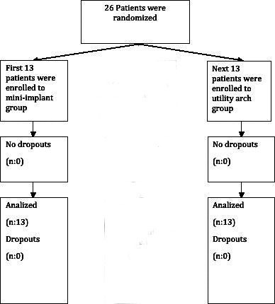
The flow chart of the study.
Fixed orthodontic treatment was performed using an 0.018-inch slot preadjusted appliance with a Roth prescription. In both groups when there wasn't enough overjet to permit bonding of lower incisors, maxillary incisors were bonded and protruded using a preformed NiTi utility arch prior to lower incisor intrusion. In group 1, metal brackets were bonded to the mandibular anterior teeth, and leveling was performed using a segmental arch. As soon as an 0.16 × 0.22–inch stainless-steel segmental arch could be inserted as a rigid segmental anterior unit, two self-drilling miniscrews (1.2-mm diameter; 6 mm long; Absoanchor, Dentos, Taegu, Korea) were placed between the mandibular lateral and canine teeth. Standard periapical radiographs were taken to check the position of the screws in relation to the neighboring roots. One week after insertion of the screws, NiTi closed-coil springs (3M Unitek, Monrovia, Calif) were adjusted to give an approximate intrusive force of 60–80 g to four lower incisor teeth (Figure 2a). All of the patients were provided with adequate information related to maintenance of the oral hygiene. The patients were followed at 4-week intervals, and force levels were checked at each follow-up visit.
Figure 2.

(a) Group 1, intrusion with mini-implants. (b) Group 2, intrusion with mandibular utility arch.
In group 2, leveling of the mandibular incisors was performed, as described for group 1. After the leveling was completed, a custom-made mandibular utility arch (0.16 × 0.16–inch Blue Elgiloy wire; Ormco, Glendora, Calif) was inserted for incisor intrusion. A 45° tip back bend and 45° of buccal root torque were bent into the molar segment, and 5–10° of lingual crown torque was placed in the incisor segment, as proposed by Bench et al.7 The intrusive force of 75 g was checked before tying the archwire, and the force levels were checked every 4 weeks (Figure 2b).
Intrusion was completed when the incisors were at the same level as the mesiobuccal cusps of the mandibular first molars. Conventional lateral cephalometric radiographs were taken at pretreatment and at the end of intrusion. An additional lateral cephalometric radiograph postleveling was not taken to reduce the amount of radiation absorbed by the patients. The radiographs were traced in a dark room on a light box. A constructed Frankfort horizontal reference plane (7° to sella nasion line) was used as the horizontal reference. A vertical reference plane perpendicular to the horizontal reference was constructed from point T (the most superior point of the anterior wall of the Sella Turcica at the junction with the tuberculum sella). Thirty landmarks were identified, yielding 23 linear and 20 angular measurements.
In order to evaluate the other mandibular dental changes, a corpus axis was constructed using Xi point and Pm point, as proposed by Ricketts.11 The center of resistance of the mandibular central incisor was taken as a point located at one-third of the distance of the root length apical to the alveolar crest.12 The landmarks and reference planes are shown in Figure 3, and local mandibular measurements are shown in Figure 4.
Figure 3.
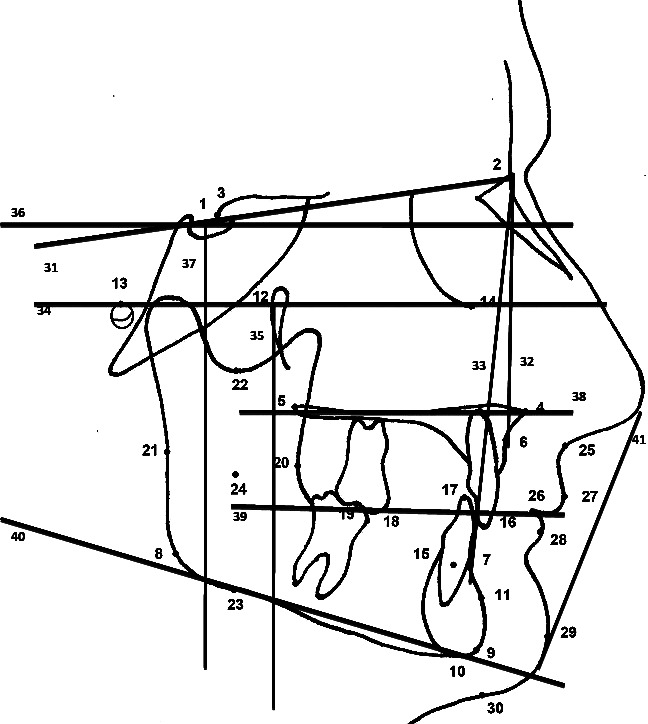
Landmarks and reference planes used in this study. 1. Sella (S); 2. Nasion (N); 3. T point; 4. Anterior nasal spine; 5. Posterior nasal spine; 6. A point; 7. B point; 8. Gonion (Go); 9. Gnathion (Gn); 10. Menton (Me); 11. Supra pogonion (Pm); 12. Pterygomaxillary point (Pt); 13. Porion (Po); 14. Orbitale (Or); 15. Center of resistance of mandibular incisor (CR); 16. Incisal edge of maxillary 1; 17. Incisal edge of mandibular 1; 18. Mesiobuccal cusp tip of mandibular first molar; 19. Mesiobuccal cusp tip of maxillary first molar; 20. R1 point of Ricketts; 21. R2 point of Ricketts; 22. R3 point of Ricketts; 23. R4 point of Ricketts; 24. Xi point of Ricketts; 25. Subnasale (Sn); 26. Stomion (St); 27. Labiale superius (Ls); 28. Labiale inferius (Li); 29. Soft tissue pogonion (Pg′); 30. Soft tissue menton (Me′); 31. Sella-Nasion plane (SN); 32. NA plane (NA); 33. NB plane (NB); 34. Frankfort horizontal plane (FH); 35. Pterygoid vertical-PTV plane; 36. Horizontal reference plane (HRP); 37. Vertical reference plane (VRP); 38. Palatal plane (PP); 39. Occlusal plane (OP); 40. Mandibular plane; 41. Ricketts' E-plane.
Figure 4.
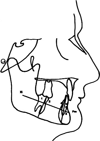
Landmarks and reference planes for local mandibular measurements. 1. Xi-Pm/Mand6 angle; 2. Xi-Pm-Mand6 distance (mm); 3. Xi-Pm/Mand1 angle; 4. Xi-Pm-Mand1(tip) distance (mm); 5. Xi-Pm-Mand1 (cr) distance (mm).
Statistical Analysis
Analyses of the obtained data were conducted using SPSS for Windows (version 11.5). Normal distribution of the data was evaluated using a Shapiro-Wilk test. Descriptive statistical values were given as mean ± standard deviation for parametric results and as median (minimum-maximum) for nonparametric data. The data were evaluated using a 95% confidence interval. In order to reduce type I error, a Bonferroni correction was applied.
One week after tracing the cephalograms, 15 randomly selected cephalograms were retraced by the same investigator. Method error was calculated using intraclass correlation coefficients. The results all showed values between 0.95 and 1.00. Pretreatment values of the groups were compared using two-factor repeated-measures analysis of variance or a Mann-Whitney U-test. Intragroup comparisons were made using a paired t-test or a Wilcoxon test. Intergroup comparisons were made using a Student's t-test or a Mann-Whitney U-test. All statistical analyses were performed by a statistical expert.
RESULTS
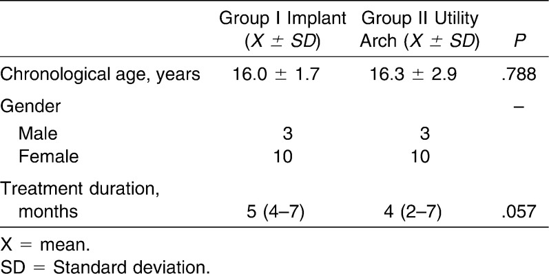
The duration of intrusion achieved was 5 months for group 1 and 4 months for group 2 (Table 1). The mean amount of change was 0.4 mm/mo for the incisor tip and 0.3 mm/mo for the center of resistance in the implant group and 0.25 mm/mo for the incisor tip and 0.2 mm/mo for the center of resistance in the utility arch group. The duration of intrusion was not statistically significant between the groups (P > .05). Out of 26 implants that were inserted in group 1, only four showed mobility during intrusion. Two of these were still loaded as a result of the fact that intrusion was about to be completed and so only two of the implants were replaced. Three of these mobile implants were on the left side.
Table 1.
Demographics of the Study Group
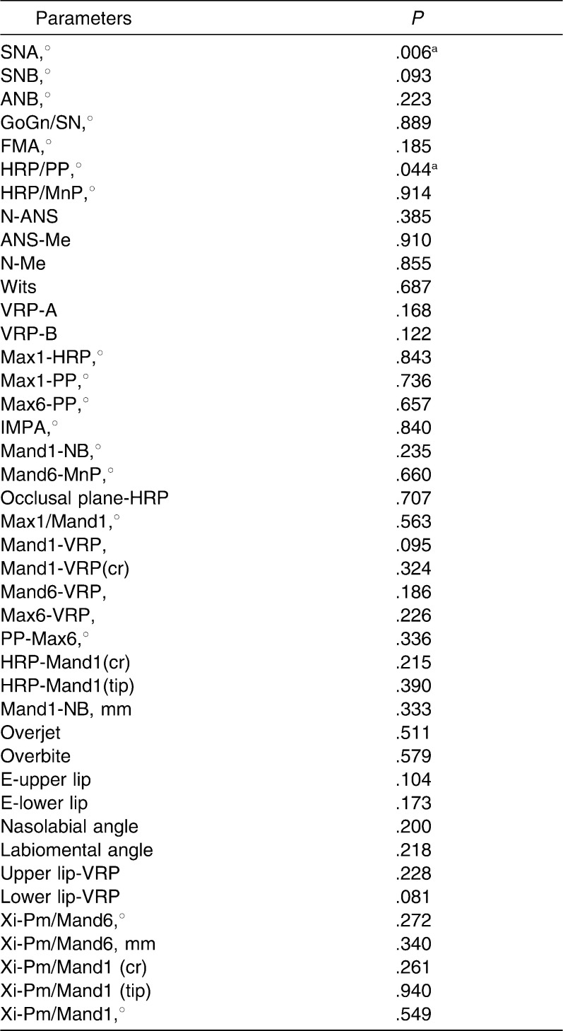
When pretreatment values of the groups were evaluated, values showed differences in the SNA (°) (P = .006) and HRP-PP (°) (P = .044) measurements. Other values showed similarities between the groups. Pretreatment comparison of the groups is shown in Table 2.
Table 2.
Statistical Comparisons of the Pretreatment Values of the Groups
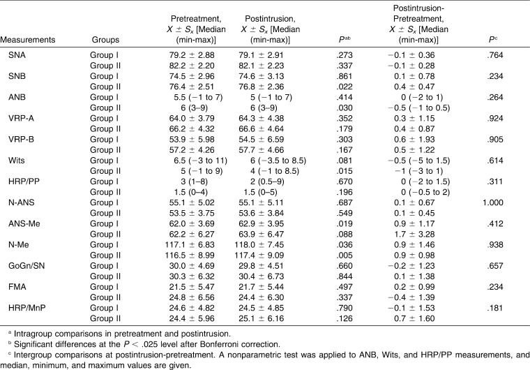
Sagittal relations showed statistically significant changes during intrusion in the SNB angle for the utility arch group. However, intergroup differences were insignificant (P > .05). GoGn/SN, FMA, and HRP/MnP measurements, which represent change in the vertical dimension, did not show significant differences in both intragroup and intergroup analyses (P > .05). Skeletal measurements and their statistical evaluations are given in Table 3.
Table 3.
Skeletal Measurements and their Statistical Evaluation
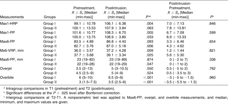
Maxillary incisors were protruded with a preformed utility arch in patients with inadequate overjet to permit bonding of lower incisors. In the implant group, a significant amount of protrusion was measured for the upper incisors (P < .025). However, this change was not significant for the utility arch group. Conversely, the amount of distal tipping of molars was significant for the utility arch group (Max6-PP°, P = .006). These differences in the upper teeth were not found to be significant for either group (P > .025) (Table 4).
Table 4.
Maxillary Dental Measurements and Statistical Evaluation
The amount of overjet change was not significant for either group (P > .025), whereas the change in overbite was significant for both groups (P < .025). The intergroup differences were not statistically significant (P > .025).
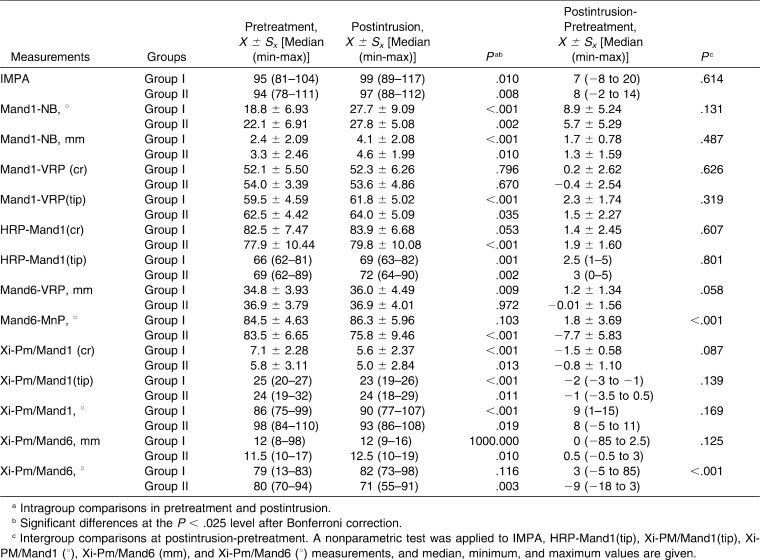
Mandibular dental movements were analyzed in terms of both sagittal and vertical direction. IMPA showed an increase of 7° in the implant group and 8° in the utility arch group; both increases were considered significant. Mand1-NB angle and distances and Xi-Pm/mand1 angle showed increases in both groups (P < .025, P < .025, and P < .025). The mandibular incisor tip relative to the vertical reference showed an increase with the utility arch, but the movement of the center of resistance was not significant. These differences in sagittal incisor movements were not significant between the groups (P > .025) (Table 5).
Table 5.
Mandibular Measurements and their Statistical Evaluations
Vertical movement of mandibular incisors was evaluated from both incisor tip and the center of resistance. The vertical change in incisor tip showed similar differences between the groups, which were also significant. The linear measurements that represent the position of the center of resistance, which show the amount of pure intrusion, were significant for both groups in parameters Mand 1-HRP (cr) and Xi-Pm/mand 1 (cr). The differences between the groups were not statistically significant (P > .025).
The amount of molar movement was different between the groups. The amount of angular change of mandibular molars was significant in the utility arch group in both Mand6-MnP (°) and Xi-Pm/mand 6 (°). The vertical change in molar position, as measured by the Xi-Pm/mand 6 parameter, showed similar differences between the groups. Intergroup differences were also significant for angular changes.
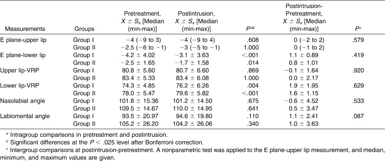
As soft tissue changes were evaluated, upper lip measurements (E plane/upper lip, upper lip-VRP) did not show significant differences. However, significant differences were measured for lower lip position in E plane/lower lip and lower lip-VRP parameters for both groups. Intergroup changes were also found to be similar (Table 6).
Table 6.
Soft Tissue Measurements and their Statistical Evaluations
DISCUSSION
Correction of deep overbite is one of the fundamental goals of orthodontic treatment. Continuous arches provide rapid correction through both incisor proclination and posterior extrusion, but extrusion of posterior teeth is not always stable, especially in adult patients. Intrusion using segmental arches not only provides accurate prediction of forces or moments but also minimizes counteracting side effects. A vast number of reports5,13–17 have been published over the years regarding upper or lower incisor intrusion using segmental arches.
After the revolutionary introduction of temporary bone anchorage devices (TADs) for orthodontic usage, several clinicians applied segmental mechanics with the support of TADs. Movements such as en masse retraction of anterior teeth, canine distalization, and tooth uprighting are completed with less difficulty and less patient dissatisfaction. In two recent studies15,16 it was shown that pure upper incisor intrusion could be achieved using a segmental arch to the incisors when it is supported by two mini-implants that are placed between the lateral and canine teeth. However, nowadays treatment of deep bite via upper incisor intrusion is questioned as a result of the potential negative effects on smile esthetics. With this in mind, the present study aimed to investigate the effects of TAD-supported lower incisor intrusion and to compare these effects with those achieved using a conventional-mechanics, intrusion utility arch.
The amount of interradicular bone available for mini-implant placement was investigated by Schnelle et al.18 using panoramic radiography and by Poggio et al.19 using volumetric dental tomography. According to the results of both studies, the amount of mandibular bone thickness decreases toward the anterior area, and mandibular interradicular areas were not considered ‘safe zones.’ Twenty-six implants were inserted in the present study group, and four of these showed mobility during intrusion (92.4% success). As the intrusion was about to be completed, two of these mobile implants were still loaded and the other two were replaced. In addition to bone quality, different factors, such as the geometry of the implant, the operator's skill and experience, and insertion technique, determine the success of an implant.20 Three of the mobile implants were on the right side of the patient. The probable reason for these failures may be the operator's ease (or difficulty) of placement on one side. Schnelle et al.18 and Hu et al.21 advised placement of implants of the smallest diameter and length in these risky areas in order to achieve stability. In this study, if higher force levels were used, the success rate might have been different.
The dentofacial effects that were achieved were similar in both of the groups. The mean amount of overbite decrease was 3 mm for the implant group and 3.5 mm for the utility arch group, which was similar between the groups. The vertical and sagittal mandibular incisor movement showed only minimal differences, which were not statistically significant between the groups. The sagittal movement of the incisor tip was 2.3 mm in the implant group and 1.5 mm in the utility arch group. When this movement is interpreted, it should be kept in mind that the initial cephalometric records were taken at the beginning of treatment, not at the beginning of intrusion. A minimal amount of protrusion is expected during segmental leveling of incisors. Vertical movement of the center of resistance was 1.9 mm in the implant group and 1.4 mm in the utility arch group. Several studies21–24 have found various amounts of lower incisor intrusion (1.02–3 mm) with conventional mechanics. In these studies protrusion of the lower incisors followed intrusion. In this study, the only difference found between conventional intrusion and intrusion with TADs was distal molar tipping in the utility arch group. The molars were not used for anchorage when TADs were used, and, therefore, no posterior movement was detected.
The similarities between the two treatment strategies may be attributed to two possible factors. One of these is the location of the center of resistance. The center of resistance of the upper incisors was investigated in several studies, but the literature lacks precise information about the center of resistance of lower incisors. In only one study, which was conducted by Shimatsu,25 the location of the center of resistance of four lower incisors was shown to be between the lateral and canines and vertically, halfway on the root length. However, if the CR is slightly distal to this, protrusion during intrusion is inevitable. One other factor that was considered was the force applied. A variety of force levels were administered for lower incisor intrusion. Burstone6 advised using 40 g of force for four mandibular incisors. Likewise, Weiland et al.5 applied 40–50 g. Some authors, such as Bench et al.7 (75 g for four incisors or 20 g per tooth) and McNamara26 (25 g per tooth), advised higher force levels. In conventional mechanics, the forces are distributed between incisors and molars. Since there is no molar anchorage in the implant group, lower force levels would be more efficient in providing pure intrusion. However, further studies are needed to confirm these assumptions.
Root resorption is the most serious side effect of orthodontic treatment, and intrusion movement is most prone to this complication. Periodontal and periapical effects of the present study sample were also investigated, and the results will be presented elsewhere.
CONCLUSIONS
The incisor intrusion that was achieved using TAD-supported segmented archwire was no different than the movement achieved by the conventional intrusion utility arch.
As the mandibular molars were not included in the anchorage unit in the implant group, the only difference between the two methods involved molar movement.
REFERENCES
- 1.Nielsen L. Vertical malocclusions: etiology, development, diagnosis and some aspects of treatment. Angle Orthod. 1991;61:247–260. doi: 10.1043/0003-3219(1991)061<0247:VMEDDA>2.0.CO;2. [DOI] [PubMed] [Google Scholar]
- 2.Nanda R. The differential diagnosis and treatment of excessive overbite. Dent Clin North Am. 1981;25:69–84. [PubMed] [Google Scholar]
- 3.Sarver D. M, Ackerman M. B. Dynamic smile visualization and quantification: part 2: smile analysis and treatment strategies. Am J Orthod Dentofac Orthop. 2003;124:116–127. doi: 10.1016/s0889-5406(03)00307-x. [DOI] [PubMed] [Google Scholar]
- 4.Zachrisson B. U. Facial esthetics: guide to tooth positioning and maxillary incisor display. World J Orthod. 2007;3:308–314. [PubMed] [Google Scholar]
- 5.Weiland F. J, Banthleon H, Droschi H. Evaluation of continuous arch and segmented arch levelling techniques in adult patients—a clinical study. Am J Orthod Dentofac Orthop. 1996;110:647–655. doi: 10.1016/s0889-5406(96)80042-4. [DOI] [PubMed] [Google Scholar]
- 6.Burstone C. R. Deep overbite correction by intrusion. Am J Orthod. 1977;72:1–22. doi: 10.1016/0002-9416(77)90121-x. [DOI] [PubMed] [Google Scholar]
- 7.Bench R. W, Gugino C. F, Hilgers J. J. Bioprogressive therapy part 6. J Clin Orthod. 1978;12:123–139. [PubMed] [Google Scholar]
- 8.Kanomi R. Mini-implant for orthodontic anchorage. J Clin Orthod. 1997;31:763–767. [PubMed] [Google Scholar]
- 9.Lee J. S, Kim J. K, Park Y. C, Vanarsdall R. L. Applications of Orthodontic MiniImplants. Hanover Park, Ill: Quintessence Publishing Co, Inc; 2007. p. 222. [Google Scholar]
- 10.Bacetti T, Franchi L, McNamara J. A. An improved version of the cervical vertebral maturation method for the assessment of mandibular growth. Angle Orthod. 2002;72:316–323. doi: 10.1043/0003-3219(2002)072<0316:AIVOTC>2.0.CO;2. [DOI] [PubMed] [Google Scholar]
- 11.Ricketts R. M. Perspectives in the clinical application of cephalometrics. Angle Orthod. 1981;51:115–150. doi: 10.1043/0003-3219(1981)051<0115:PITCAO>2.0.CO;2. [DOI] [PubMed] [Google Scholar]
- 12.Burstone C. J. The biomechanics of tooth movement. In: Kraus B. S, editor. Vistas in Orthodontics. Philadelphia, Pa: Lea & Febiger; 1962. pp. 197–213. [Google Scholar]
- 13.Uribe F, Nanda R. Treatment of Class II division 2 malocclusion in adults: biomechanical considerations. J Clin Orthod. 2003;37:599–606. [PubMed] [Google Scholar]
- 14.Kim T. W, Kim H, Lee S. J. Correction of deep overbite and gummy-smile by using a mini-implant with a segmented wire in a growing Class II division 2 patient. Am J Orthod Dentofac Orthop. 2006;130:676–685. doi: 10.1016/j.ajodo.2005.07.013. [DOI] [PubMed] [Google Scholar]
- 15.Polat-Ozsoy O, Arman-Ozcirpici A, Veziroglu F. Miniscrews for upper incisor intrusion. Eur J Orthod. 2009;31:412–416. doi: 10.1093/ejo/cjn122. [DOI] [PubMed] [Google Scholar]
- 16.Saxena R, Kumar R. S, Upadhyay U, Naik V. A clinical evaluation of orthodontic mini-implants as intraoral anchorage for the intrusion of maxillary anterior teeth. World J Orthod. 2010;11:346–351. [PubMed] [Google Scholar]
- 17.Shroff B, Yoon W. M, Lindauer S. J, Burstone C. J. Simultaneous intrusion and retraction using a three-piece base arch. Angle Orthod. 1997;67:455–461. doi: 10.1043/0003-3219(1997)067<0455:SIARUA>2.3.CO;2. [DOI] [PubMed] [Google Scholar]
- 18.Schnelle M. A, Beck F. M, Jaynes R. M, Huja S. S. A radiographic evaluation of the availability of bone for placement of miniscrews. Angle Orthod. 2004;74:830–835. doi: 10.1043/0003-3219(2004)074<0832:AREOTA>2.0.CO;2. [DOI] [PubMed] [Google Scholar]
- 19.Poggio P. M, Incorvati C, Velo S, Carano A. ‘Safe zones’: a guide for miniscrew positioning in the maxillary and mandibular arch. Angle Orthod. 2006;76:191–197. doi: 10.1043/0003-3219(2006)076[0191:SZAGFM]2.0.CO;2. [DOI] [PubMed] [Google Scholar]
- 20.Park H. S, Jeong S. H, Kwon O. W. Factors affecting the clinical success of screw implants used as orthodontic anchorage. Am J Orthod Dentofac Orthop. 2006;130:18–25. doi: 10.1016/j.ajodo.2004.11.032. [DOI] [PubMed] [Google Scholar]
- 21.Hu K, Kang M, Ki T, Kim K, Kim H. Relationships between dental roots and surrounding tissues for orthodontic miniscrew installation. Angle Orthod. 2009;79:37–45. doi: 10.2319/083107-405.1. [DOI] [PubMed] [Google Scholar]
- 22.Gordon J. B. Lower Incisor Intrusion in Low Mandibular Plane Angle Deep Bite Cases [master's thesis] Los Angeles, Calif: University of California–Los Angeles; 1997. [Google Scholar]
- 23.Greig D. G. M. Bioprogressive therapy: overbite reduction with the lower utility arch. Br J Orthod. 1983;10:214–216. doi: 10.1179/bjo.10.4.214. [DOI] [PubMed] [Google Scholar]
- 24.Dake M. L, Sinclair P. M. A comparison of the Ricketts and Tweed type arch levelling techniques. Am J Orthod Dentofac Orthop. 1989;95:72–78. doi: 10.1016/0889-5406(89)90138-8. [DOI] [PubMed] [Google Scholar]
- 25.Shimatsu M. Determination of the center of resistance of mandibular anterior arch segments. Orthod Waves. 2008;67:95–107. [Google Scholar]
- 26.McNamara J. A., Jr Utility arches. J Clin Orthod. 1986;20:452–456. [PubMed] [Google Scholar]


