Abstract
Objective:
To assess whether the values of different measurements taken on three-dimensional (3D) reconstructions from cone-beam computed tomography (CBCT) are comparable with those taken on two-dimensional (2D) images from conventional lateral cephalometric radiographs (LCRs) and to examine if there are differences between the different types of CBCT software when taking those measurements.
Material and Methods:
Eight patients were selected who had both an LRC and a CBCT. The 3D reconstructions of each patient in the CBCT were evaluated using two different software packages, NemoCeph 3D and InVivo5. An observer took 10 angular and 3 linear measurements on each of the three types of record on two different occasions.
Results:
Intraobserver reliability was high except for the mandibular plane and facial cone (from the LCR), the Na-Ans distance (using NemoCeph 3D), and facial cone and the Ans-Me distance (using InVivo5). No statistically significant differences were found for the angular and linear measurements between the LCRs and the CBCTs for any measurement, and the correlation levels were high for all measurements.
Conclusion:
No statistically significant differences were found between the angular and linear measurements taken with the LCR and those taken with the CBCT. Neither were there any statistically significant differences between the angular or linear measurements using the two CBCT software packages.
Keywords: 2D, 3D, CBCT, LCR, Cephalometric, Measurement
INTRODUCTION
Cephalometric analysis is one of the key tools in undertaking an accurate diagnosis in orthodontics, even though it presents a number of limitations given that it reduces to two dimensions a three-dimensional (3D) object by projecting all structures onto a single plate, thereby creating difficulties when it comes to understanding and undertaking an adequate analysis. Moreover, cephalometric analysis has other technical limitations as the images obtained can be distorted because of mistakes associated with the X-ray apparatus or errors in the positioning of the patient's head.
Conventional medical computed tomography (CT) was developed to analyze 3D structures on the three spatial planes and so provide a more realistic image, although the high cost of 3D reconstruction and the high dosage of radiation involved limited its use. Cone-beam computed tomography (CBCT)1,2 was then developed to reduce the radiation dosage, achieve greater precision on the three spatial planes, and reduce the costs associated with CT.3
The accuracy4–16 and reproducibility11,14 of cephalometric landmarks have been widely studied for CT4,17,18 and CBCT5,10,12,13,19 by evaluating the location of those landmarks20 or by comparing the linear and angular measurements15,21–23 taken on lateral cephalometric radiographs (LCR) with two-dimensional (2D) projections (orthogonal, in perspective, maximum-intensity projection [MIP], projection similar to x-ray [RaySum]), obtained from slices of a CBCT scan. The results for landmark location were similar for both methods,20–22 greater reproducibility being found in the projections from CBCT than from LCR, although there were no clinically significant results.23 It has also been observed that the RaySum projection is more reproducible than the MIP and that either projection could replace LCR, thus making LCRs unnecessary when a CBCT has previously been undertaken on a patient.15,21–23
However, for frontal projections, other authors found statistically significant differences, as they saw that the positioning of the patient's head24 influenced the measurement.
Other studies concluded that in order to adjust the location of cephalometric landmarks, slices were more accurate than the 3D view provided, because 3D projection did not represent real surfaces.14 Nevertheless, these results differed from those of other studies that found linear measurements undertaken directly on 3D images to be more accurate.25
As there are few studies that compare the cephalometric values obtained from LCR with those from 3D projection of CBCT, and as we wanted to determine the compatibility of different CBCTs in common cephalometric analyses, the aims of our study were, first, to check whether the angular and linear measurements of 3D reconstructions obtained from a CBCT are equal to those of 2D images obtained from the LCR, and second, to check whether there are differences between two CBCT software packages (Beta Nemoceph 3D, Software Nemotec, SL, Madrid, Spain and InVivo5 Anatomage, San Jose, Ca) when taking those measurements.
MATERIALS AND METHODS
The sample was distributed as follows: four women and four men between the ages of 8 and 30 years old. Mean (±SD) age = 15.55 ± 6.25 years old.
Eight patients were selected. Those patients had undergone both an LCR and a CBCT before treatment and within 3 months of each other. The CBCTs had been taken because some of these patients were going to undergo orthognathic surgery and the others presented with inclusions of maxillary canines.
The LCRs were taken using a cephalostat Orthophos Plus DS (Sirona Dental Systems GmbH, Germany) with a radiation time of 16 seconds for an exposure time of 0.4 seconds, the tube voltage being 73 kV and the intensity 15 mAs, whereas the CBCTs were taken using i-CAT equipment (Imaging Sciences International, Hatfield, Pa) that generates a total of 326 slices, with an image matrix size of 400 × 400 in medium-quality and high-resolution mode. The field of view (FOV) used was the portrait mode, which gathers data in extended FOV mode and covers the full skull of 170 mm in height × 230 mm in diameter with a scanning time of 8.9 seconds. Voxel size was 0.4 × 0.4 × 0.4 mm, the tube voltage being 120 kV and the intensity 23.87 mAs. The size of the data files created is 35 megabytes.
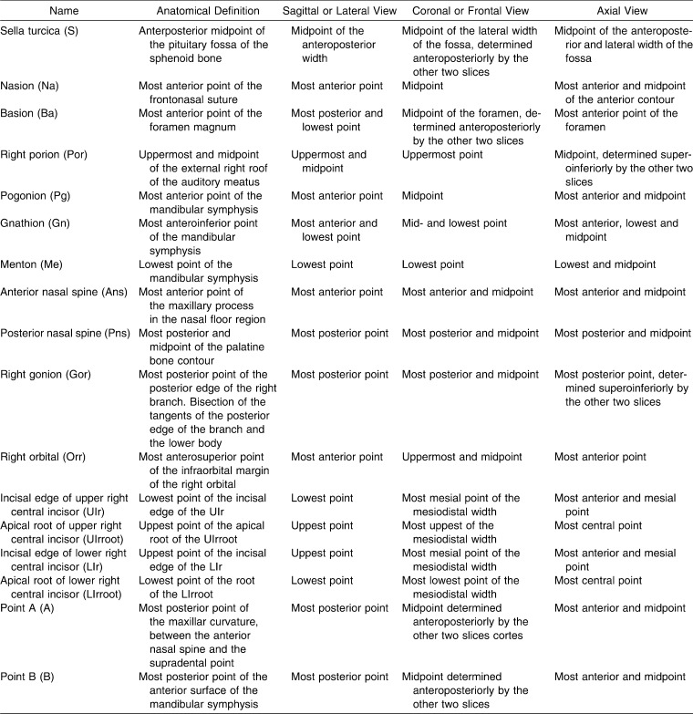
To carry out this study, 17 cephalometric landmarks were located. These are described from the three spatial planes in Table 1a. Then, 10 angular and 3 linear measurements were taken (Table 1b).
Table 1a.
Definition of the Three Spatial Planes of the 17 Cephalometric Landmarks Used in This Study
Table 1b.
Description of Angular and Linear Measurements Used in This Study
The LCRs were digitalized using a conventional scanner-type HP Scan Jet II Cx/T (Hewlett Packard Development Company LP, Palo Alto, Ca), and the location of the landmarks was measured using the Nemotec Dental Studio NX program (Software Nemotec SL, Madrid, Spain).
The raw data and slices obtained from the CBCTs were imported to two different software packages where 3D reconstruction was undertaken. Location of the cephalometric landmarks for each of the two CBCT software packages was undertaken by creating different types of projections (multiplanar reconstruction, RaySum, MIP) on the sagittal, coronal, and axial views and to the volumetric reconstruction (3D).
First, to fine-tune the location of points using the Beta NemoCeph 3D software (Software Nemotec SL, Madrid, Spain), two windows were created for the sagittal view and another two for the coronal or frontal view, which, moreover, can be enlarged to full screen using the zoom. By doing so, we can simultaneously observe the right and left sides or have two projections of the same side open for the sagittal view, or, for the coronal view, have two different projections open at the same time (Figure 1). To locate each landmark, the slice of the most appropriate plane was selected before fitting it onto the other planes for greater accuracy.
Figure 1.
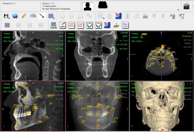
Location of the cephalometric landmarks in the Beta NemoCeph 3D® software package.
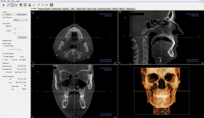
Second, to locate landmarks using the InVivo5 software (Anatomage, San Jose, Calif), the program allows one to view either a part or the whole skull by navigating across the slices so as to choose the most appropriate one for locating each point (Figure 2).
Figure 2.
Location of the cephalometric landmarks in the InVivo5® software package.
All measurements were undertaken by a single observer previously trained and qualified in the location of cephalometric landmarks and with six years of experience/background in orthodontics. The measurements were taken on two different occasions with an interval of one week between the first and second measurements so as to measure the intraobserver error.
All variables and measurements were introduced onto a version 12.0 Excel spreadsheet (Microsoft Corp, Redmond, Wa) and then analyzed using version 17.0 of the statistics package SPSS for Windows (IBM Corp, Somers, NY). To calculate the reproducibility of each of the systems used, a t-test was undertaken for related samples. To determine reliability of the different types of systems, a repeated measurement analysis of variance was undertaken using a variance factor, by means of Scheffé's adjustment for multiple comparisons, through the means obtained from the first and second observations for that purpose. Differences were considered significant at P < .05.
RESULTS
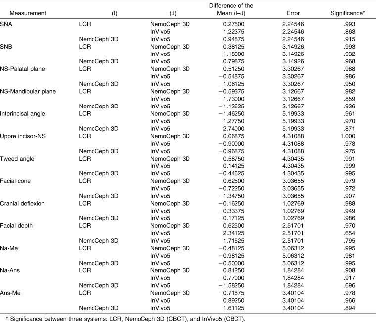
The results obtained from this study are shown in Tables 2 and 3 and in Figure 3.
Table 2.
Intraobserver Reliability Between the First and Second Measurement*
Table 3.
Multiple Comparisons Using the Scheffé Method
Figure 3.
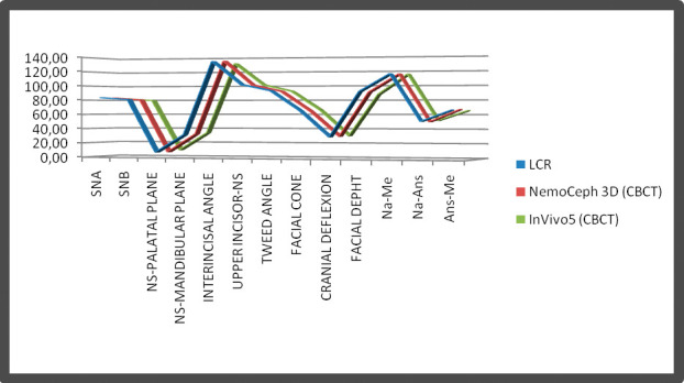
Comparison between the three methods. Means of all values provided.
Table 2 shows the intraobserver reproducibility between the first and second measurement for each of the methods. In the measurements taken on the LCR, a statistically significant difference can be observed in the angle of the mandibular plane, where the maximum difference between the two measurements (first and second) was determined as being 3.60° ([3.60 ÷ 31.98] * 100 = 11.25), which means an error of 11.25%, as well as in the facial cone, with a maximum difference of 3.60° ([3.60 ÷ 65.43] * 100 = 5.5), which means an error of 5.5%. In the measurements taken with the Beta NemoCeph 3D, a difference was found for the Na-Ans distance, with a maximum difference between measurements of 2.5 mm ([2.5 ÷ 51.18] * 100 = 5), which means 5% of error in that measurement. Lastly, in the measurements taken with InVivo5, a statistically significant difference was found for the facial cone (maximum difference: 3.48°; [3.48 ÷ 66.15] * 100 = 5.3), which means 5.3% of error, and for the Ans-Me distance (maximum difference: 5.78; [5.78 ÷ 65.46] * 100 = 8.8), which means an error of 8.8%.
Table 3 shows the correlations between the three types of methods, and the correlations between the three methods are high. Only the facial cone (between LCR and InVivo5) presented lower values.
DISCUSSION
Each of the 13 variables used in this study were measured on the LCR and on the 3D reconstruction of each CBCT using the two software packages (Beta NemoCeph 3D and InVivo5) in order to compare their reproducibility and the statistically significant differences between each of the methods for the measurements analyzed.
To determine the reproducibility of the measurements and the intraobserver error, a single observer repeated all the measurements on a second occasion. We consider that it is sufficient to do so twice, as additional measurements do not provide any relevant additional information.26 Moreover, the possible systematic errors made by an observer will always be the same for the three methods. If the measurements of more observers are combined, they may lead to errors when it comes to evaluating the real variability of the measurements.26
In general, reproducibility between the first and the second measurement, both for the linear and angular measurements, was high for all three methods, with correlation indices of intraclass correlation > 0.86 in all cases except for cranial deflection and the Na-Ans distance on the LCR and InVivo5 and for facial depth with the InVivo5 software package.
The only statistically significant differences found were between the first and second measurement for the SNa-mandibular plane angle and for the facial cone measured on the LCR, for the Na-Ena distance measured using the NemoCeph 3D software package, and for the facial cone and Ans-Me distance using the InVivo5 software package.
For these measurements, a systematic error rather than a random one was found between the first and second measurements providing greater values for one measurement than the other. For this reason those measurements appear with statistically significant differences. However, in all cases the relative error determined from the maximum discrepancy has not exceeded the method error, as all the measurements taken would fall within method variability (obtained by dividing the standard deviation [SD] between the mean of each value).
On analyzing the correlations of each of the variables for the three methods, no angular or linear measurement was found with a statistically significant difference using the three techniques, although we have observed that facial depth presents the worst correlation between the three variables (between LCR and InVivo and between Beta NemoCeph 3D and InVivo5), which implies that there is a greater difference between the values of this measurement in the three methods.
In contrast to our results, Van Vlijmen et al.27 found statistically significant differences in several measurements that were measured on the LCR and on the CBCT; for example, the SNa-mandibular plane angle and the SNB angle. However, as in our study, the difference between most of the measurements was less than the SD, confirming that that difference was not clinically significant, although reproducibility of the measurements on the LCR was higher than in the 3D reconstructions. In the cases in which a 2D line and 3D plane were used for undertaking a measurement, they observed that there may be a clinically relevant difference, so 3D tracings would not be recommendable for undertaking longitudinal studies where pretreatment records had been recorded in 2D. However, measurements undertaken on a single patient who has 3D records would be of use for comparing pre- and posttreatment changes or changes due to growth. In another study28 by the same authors, which compared 2D and 3D frontal views, clinically relevant differences were found for both types of measurement. In a third study,26 the same authors compared measurements between two types of CBCT (Iluma Imtech, Ardmore, OK and iCAT, Imaging Sciences International, Inc, Hatfield, Pa), concluding that the measurement reproducibility of 3D reconstructions in Iluma was higher than in the i-CAT, finding, in addition, statistically significant differences between several angular measurements, although only two of them presented clinically relevant differences.
Yitschaky et al.29 compared angular, linear, and ratio measurements between the LCR and CT and did not find statistically significant differences, except in some measurements, such as the Witts appraisal, or in others that included the Sella point (because of the differences in their location between both records). As our results, they did not find statistically significant differences for either the Na-Me or Ans-Me distances, concluding that it is possible to use most of the values previously established in 2D for measuring 3D records, as the differences between both systems were small.
Other authors have also compared angular measurements between LCR and CT.30 They found only statistically significant differences in 2 of the 14 measurement that they carried out, upper incisor-Na and upper incisor-NS. However, in our study, we did not find such difference for the upper incisor-NS angle. They found, as we did, differences that were not statistically significant for SNA, SNB, NS-palatal plane, and Tweed angle. They concluded that 3D angular cephalometric analysis was a fairly reliable method, like the traditional 2D cephalometric analysis, and that it was also more suitable for the diagnosis of cases with complex orthodontic anomalies. Currently, it could also be a suitable alternative method to 2D cephalometry with the decrease in radiation exposure and costs in the future.
To carry out this study, records of patients who had already undergone both an LCR and a CBCT for various reasons were used. Other studies have used dry skulls to undertake the measurements, as patient irradiation is not justified unless strictly necessary. However, and despite the fact that certain studies state that soft tissues distort the measurements,26 it is necessary to undertake them with all the tissues included in order to be able to check more accurately and to get as close as possible to the daily clinical reality as far as measuring patients is concerned. The drawback of carrying out a study of these characteristics is that irradiating actual patients for this purpose is not justified and therefore the sample in our study was restricted to only eight patients.
CONCLUSIONS
No statistically significant differences were found for angular and linear measurements between the measurements taken with the LCR and those of the CBCT. The correlation indices of all measurements are very high.
There were also no statistically significant differences for any of the angular and linear measurements between the two software packages of the CBCT (NemoStudio and InVivo5). Likewise, the correlation indices found between the different measurements were very high.
REFERENCES
- 1.Arai Y, Tammisalo E, Iwai K, Hashimoto K, Shinoda K. Development of a compact computed tomographic apparatus for dental use. Dentomaxillofac Radiol. 1999;28:245–248. doi: 10.1038/sj/dmfr/4600448. [DOI] [PubMed] [Google Scholar]
- 2.Mozzo P, Procacci C, Tacconi A, Martini P. T, Andreis I. A. A new volumetric CT machine for dental imaging based on the cone-beam technique: preliminary results. Eur Radiol. 1998;8:1558–1564. doi: 10.1007/s003300050586. [DOI] [PubMed] [Google Scholar]
- 3.Mah J, Hatcher D. Diagnóstico por imagen craneofacial en ortodoncia. Capítulo 2. In: Grabber T. M, Vanarsdall R. L, Vig K. W. L, editors. Orthodontics Current Principles and Techniques. St Louis, MO: Elsevier; 2005. pp. 71–100. [Google Scholar]
- 4.Kitaura H, Yonetsu K, Kitamori H, Kobayashi K, Nakamura T. Standardization of 3-D CT measurements for length and angles by matrix transformation in the 3-D coordinate system. Cleft Palate Craniofac J. 2000;37:349–356. doi: 10.1597/1545-1569_2000_037_0349_sodcmf_2.3.co_2. [DOI] [PubMed] [Google Scholar]
- 5.Pinsky H. M, Dyda S, Pinsky R. W, Misch K. A, Sarment D. P. Accuracy of three-dimensional measurements using cone-beam CT. Dentomaxillofac Radiol. 2006;35:410–416. doi: 10.1259/dmfr/20987648. [DOI] [PubMed] [Google Scholar]
- 6.Lascala C. A, Panella J, Marques M. M. Analysis of the accuracy of linear measurements obtained by cone beam computed tomography (CBCT-NewTom) Dentomaxillofac Radiol. 2004;33:291–294. doi: 10.1259/dmfr/25500850. [DOI] [PubMed] [Google Scholar]
- 7.Marmulla R, Wörtche R, Mühling J, Hassfeld S. Geometric accuracy of the NewTom 9000 Cone Beam CT. Dentomaxillofac Radiol. 2005;34:28–31. doi: 10.1259/dmfr/31342245. [DOI] [PubMed] [Google Scholar]
- 8.Mischkowski R. A, Pulsfort R, Ritter L, Neugebauer J, Brochhagen H. G, Keeve E, Zöller J. E. Geometric accuracy of a newly developed cone-beam device for maxillofacial imaging. Oral Surg Oral Med Oral Pathol Oral Radiol Endod. 2007;104:551–559. doi: 10.1016/j.tripleo.2007.02.021. [DOI] [PubMed] [Google Scholar]
- 9.Moshiri M, Scarfe W. C, Hilgers M. L, Scheetz J. P, Silveira A. M, Farman A. G. Accuracy of linear measurements from imaging plate and lateral cephalometric images derived from cone-beam computed tomography. Am J Orthod Dentofacial Orthop. 2007;132:550–560. doi: 10.1016/j.ajodo.2006.09.046. [DOI] [PubMed] [Google Scholar]
- 10.Moerenhout B. A, Gelaude F, Swennen G. R, Casselman J. W, Van Der Sloten J, Mommaerts M. Y. Accuracy and repeatability of cone-beam computed tomography (CBCT) measurements used in the determination of facial indices in the laboratory setup. J Craniomaxillofac Surg. 2008;22:1–6. doi: 10.1016/j.jcms.2008.07.006. [DOI] [PubMed] [Google Scholar]
- 11.Lagravère M. O, Carey J, Toogood R. W, Major P. W. Three-dimensional accuracy of measurements made with software on cone-beam computed tomography images. Am J Orthod Dentofacial Orthop. 2008;134:112–116. doi: 10.1016/j.ajodo.2006.08.024. [DOI] [PubMed] [Google Scholar]
- 12.Stratemann S. A, Huang J. C, Maki K, Miller A. J, Hatcher D. C. Comparison of cone beam computed tomography imaging with physical measures. Dentomaxillofac Radiol. 2008;37:80–93. doi: 10.1259/dmfr/31349994. [DOI] [PubMed] [Google Scholar]
- 13.Periago D. R, Scarfe W. C, Moshiri M, Scheetz J. P, Silveira A. M, Farman A. G. Linear accuracy and reliability of cone beam CT derived 3-dimensional images constructed using an orthodontic volumetric rendering program. Angle Orthod. 2008;78:387–395. doi: 10.2319/122106-52.1. [DOI] [PubMed] [Google Scholar]
- 14.Oliveira A. E, Cevidanes L. H, Phillips C, Motta A, Burke B, Tyndall D. Observer reliability of three-dimensional cephalometric landmark identification on cone-beam computerized tomography. Oral Surg Oral Med Oral Path Oral Radiol Endod. 2009;107:256–265. doi: 10.1016/j.tripleo.2008.05.039. [DOI] [PMC free article] [PubMed] [Google Scholar]
- 15.Kumar V, Ludlow J. B, Mol A, Cevidanes L. Comparison of conventional and cone beam CT synthesized cephalograms. Dentomaxillofac Radiol. 2007;36:263–269. doi: 10.1259/dmfr/98032356. [DOI] [PubMed] [Google Scholar]
- 16.Cattaneo P. M, Melsen B. The use of cone-beam computed tomography in an orthodontic department in between research and daily clinic. World J Orthod. 2008;9:269–282. [PubMed] [Google Scholar]
- 17.Kobayashi K, Shimod S, Nakagawa Y, Yamamoto A. Accuracy measurement of distance using limited cone-beam computerized tomography. Int J Oral Maxillofac Implants. 2004;19:228–231. [PubMed] [Google Scholar]
- 18.Suri S, Utreja A, Khandelwal N, Mago S. K. Craniofacial computerized tomography analysis of the midface of patients with repaired complete unilateral cleft lip and palate. Am J Orthod Dentofacial Orthop. 2008;134:418–429. doi: 10.1016/j.ajodo.2006.09.065. [DOI] [PubMed] [Google Scholar]
- 19.Brown A. A, Scarfe W. C, Scheetz J. P, Silveira A. M, Farman A. G. Linear accuracy of cone beam CT derived 3D images. Angle Orthod. 2009;79:150–157. doi: 10.2319/122407-599.1. [DOI] [PubMed] [Google Scholar]
- 20.Grauer D, Cevidanes L, Styner M. A, Heulfed I, Harmon E. T, Zhuf H, Proffit W. R. Accuracy and landmark error calculation using cone-beam computed tomography–generated cephalograms. Angle Orthod. 2010;80:286–294. doi: 10.2319/030909-135.1. [DOI] [PMC free article] [PubMed] [Google Scholar]
- 21.Cattaneo P. M, Bloch C. B, Calmar D, Hjortshøj M, Melsen B. Comparison between conventional and cone-beam computed tomography–generated cephalograms. Am J Orthod Dentofacial Orthop. 2008;134:798–802. doi: 10.1016/j.ajodo.2008.07.008. [DOI] [PubMed] [Google Scholar]
- 22.Lamichane M, Anderson N. K, Rigali P. H, Seldin E. B, Wille L. A. Accuracy of reconstructed images from cone-beam computed tomography scans. Am J Orthod Dentofacial Orthop. 2009;136:156.e1–6. doi: 10.1016/j.ajodo.2009.04.006. [DOI] [PubMed] [Google Scholar]
- 23.Van Vlijmen O. J, Bergé S. J, Swennen G. R, Bronkhorst E. M, Katsaros C, Kuijpers-Jagtman A. M. Comparison of cephalometric radiographs obtained from cone-beam computed tomography scans and conventional radiographs. J Oral Maxillofac Surg. 2009;67:92–97. doi: 10.1016/j.joms.2008.04.025. [DOI] [PubMed] [Google Scholar]
- 24.Van Vlijmen O. J, Bergé S. J, Bronkhorst E. M, Swennen G. R, Katsaros C, Kuijpers-Jagtman A. M. A comparison of frontal radiographs obtained from cone beam CT scans and conventional frontal radiographs of human skulls. Int J Oral Maxillofac Surg. 2009;38:773–778. doi: 10.1016/j.ijom.2009.02.024. [DOI] [PubMed] [Google Scholar]
- 25.Hassan B, Stelt P, Sanderink G. Accuracy of three-dimensional measurements obtained from cone beam computed tomography surface-rendered images for cephalometric analysis: influence of patient scanning position. Eur J Orthod. 2009;31:129–134. doi: 10.1093/ejo/cjn088. [DOI] [PubMed] [Google Scholar]
- 26.Van Vlijmen O. J, Rangel F. A, Bergé S. J, Bronkhorst E. M, Becking A. G, Kuijpers-Jagtman A. M. Measurements on 3D models of human skulls derived from two different cone beam CT scanners. Clin Oral Investig. 2010 doi: 10.1007/s00784-010-0440-8. Jul 17 (Epub ahead of print) [DOI] [PubMed] [Google Scholar]
- 27.Van Vlijmen O. J, Maal T, Bergé S. J, Bronkhorst E. M, Katsaros C, Kuijpers-Jagtman A. M. A comparison between 2D and 3D cephalometry on CBCT scans of human skulls. Int J Oral Maxillofac Surg. 2010;39:156–160. doi: 10.1016/j.ijom.2009.11.017. [DOI] [PubMed] [Google Scholar]
- 28.Van Vlijmen O. J, Maal T. J, Bergé S. J, Bronkhorst E. M, Katsaros C, Kuijpers-Jagtman A. M. A comparison between two-dimensional and three-dimensional cephalometry on frontal radiographs and on cone beam computed tomography scans of human skulls. Eur J Oral Sci. 2009;117:300–305. doi: 10.1111/j.1600-0722.2009.00633.x. [DOI] [PubMed] [Google Scholar]
- 29.Yitschaky O, Redlich M, Abed Y, Faerman M, Casap N, Hiller N. Comparison of common hard tissue cephalometric measurements between computed tomography 3D reconstruction and conventional 2D cephalometric images. Angle Orthod. 2011;81:13–18. doi: 10.2319/031710-157.1. [DOI] [PMC free article] [PubMed] [Google Scholar]
- 30.Nalçaci R, Oztürk F, Sökücü O. A comparison of two-dimensional radiography and three-dimensional computed tomography in angular cephalometric measurements. Dentomaxillofac Radiol. 2010;39:100–106. doi: 10.1259/dmfr/82724776. [DOI] [PMC free article] [PubMed] [Google Scholar]


