

Abstract
Optogenetics has the potential to transform the study of the peripheral nervous system (PNS), but the complex anatomy of the PNS poses unique challenges for the focused delivery of light to specific tissues. This protocol describes the fabrication of a wireless telemetry system for studying peripheral sensory pathways. Unlike existing wireless approaches, the low-power wireless telemetry offers organ specificity via a sandwiched pre-curved tether, and enables high-throughput analysis of behavioral experiments with a channel isolation strategy. We describe the technical procedures for the construction of these devices, the wireless power transmission (TX) system with antenna coils, and their implementation for in vivo experimental applications. In total, the timeline of the procedure, including device fabrication, implantation, and preparation to begin in vivo experimentation can be completed in ~2-4 weeks. Implementation of these devices allows for chronic (>1 month) wireless optogenetic manipulation of peripheral neural pathways in freely behaving animals navigating homecage environments (up to 8).
Keywords: Wireless optogenetics, Vagal sensory pathway, Device implantation, Implantable optoelectronics, Wireless power transmission
Background
Optogenetics has transformed neuroscience by enabling the targeted manipulation of genetically defined neural cell types (Deisseroth, 2011 and 2015). This typically involves expressing a light-activated ion channel using a Cre driver mouse and implanting an optical fiber in the brain ( Park et al., 2015b , 2015a and 2016). In this way, it is possible to activate or inactivate specific cell types with light and thereby test their causal role in behavior ( Kim et al., 2013 ; Montgomery et al., 2015 ; Shin et al., 2017 ).
Optogenetics also has the potential to transform the study of the PNS, but the complex anatomy of the PNS poses unique challenges for the focused delivery of light to specific tissues ( Towne et al., 2013 ; Montgomery et al., 2016 ; Maimon et al., 2018 ). The PNS consists of sensory and motor neurons, with cell bodies located in widely distributed peripheral ganglia. The major sensory ganglia include dorsal root ganglia, which consist of clusters of cell bodies of spinal sensory neurons that are organized bilaterally along the length of the spine, and nodose ganglia, which contain the cell bodies of vagal sensory neurons (Berthoud and Neuhuber, 2000).
These two sensory systems broadly innervate a range of peripheral organs that differ in their size, shape, location, and accessibility, necessitating individualized strategies for light delivery to different tissues (Berthoud, 2008; de Lartigue, 2016; Williams et al., 2016 ). Moreover, some of these organs are highly mobile during normal physiology or behavior (e.g., movement of the intestine during digestion), which further complicates the positioning and anchoring of optical fibers. Thus, unlike in the brain, it is a considerable challenge to develop robust strategies for the delivery of light selectively to peripheral tissues in freely behaving animals.
In principle, it is possible to target peripheral tissues with light using a wired fiber optic that stimulates the animal via the back or rectum ( Caggiano et al., 2016 ; Hibberd et al., 2018 ), analogous to the intracranial fiber optics commonly used in the brain. While this approach has the advantage that it can be readily coupled with off-the-shelf components (e.g., lasers and LEDs), the abdominal viscera differs from the brain, in that it lacks a stable interface for securing large fiber optics and preventing motion. Moreover, the inflexible nature of most optical fibers can cause the shearing of tissues and nerves, or of the fiber itself, during normal animal movement. For this reason, wired fiber optics have been used less frequently for peripheral optogenetics in behaving animals ( Maimon et al., 2017 and 2018; Towne et al., 2013 ).
An alternative approach is to implant a wireless probe that internalizes the light source, thereby bypassing physical constraints associated with fiber optic cables. Strategies for such wireless, radio-frequency(RF)-powered devices have recently been described ( Montgomery et al., 2015 and 2016; Park et al., 2015a and 2015b), but it remains a major challenge to achieve long-term, organ-restricted illumination, without impeding normal behavior or physiology. For example, a wirelessly powered micro-light emitting diode (µLED) has been secured to the rat bladder using a circumferential elastomer sleeve ( Mickle et al., 2019 ), but this device impedes normal organ expansion. A wireless flexible device that sutures a µLED onto the heart surface has been reported ( Gutruf et al., 2019 ), but it has not been demonstrated to function for more than eight days, precluding most behavioral studies. More generally, affixing any µLED to a target organ surface results in light back-scatter and non-specific optogenetic illumination of nearby tissues.
Recently, we developed and published a new class of implantable wireless devices, demonstrating their applicability to study the vagus nerve ( Kim et al., 2021 ). This new wireless optogenetic implant delivers light to nerve endings from inside the stomach, via a pre-curved tether. This intragastric light delivery enables illumination of stomach innervating nerves, with much greater specificity than µLEDs affixed to the organ surface, and could in principle be extended to study other organs, such as the intestine. Here, we describe the technical procedures for the fabrication of these devices and their in vivo applications.
Materials and Reagents
Pipet tips (VWR, catalog number: 613-0239)
Glass slide (Brain Research Laboratories, catalog numbers: 5075 and 3040)
Copper/Polyimide (Cu/PI) film (DupontTM Pyralux®, catalog number: AC181200RY)
Wescorp anti-static high-temp Polyimide tape (Desco, catalog number: 81270)
Photoresistor (AZ®, catalog number: AZ1518)
Cored wire for soldering (Multicore, catalog number: 397952)
Electrical components [Supplementary Figure 1 from previous work ( Kim et al., 2021 )]
Gauze (Medique, catalog number: 60673)
6-0 Silk suture (Braintree Scientific, catalog number: NC9201232)
3-0 PGA sutures (Pro Advantage, catalog number: P420493)
5-0 PGA suture (Stoelting, catalog number: 50495)
4-0 Nylon sutures (Pro Advantage, catalog number: P420661)
Betadine (Fisher Scientific, catalog number: 19-027132)
70% Isopropyl Alcohol (Fisher, catalog number: 19-027026)
2-propanol (Fisher Chemical, catalog number: 190971)
Methyl Alcohol, Anhydrous (Macron, catalog number: 3016-16)
Acetone (Macron, catalog number: 2440-16)
Developer solution (AZ®, AZ Developer 1:1)
Copper etchant (Alfa AesarTM, catalog number: Z03E099)
Flux no-clean lead-free (Chip Quik, Inc., catalog number: SMD291NL)
Polydimethylsiloxane (PDMS) (Dow®, SylgardTM 184 Silicone Elastomer Kit)
DAPI Fluoromount-G (SouthernBiotech, catalog number: 0100-20)
Ketoprofen (Sigma, catalog number: K2012-5G)
Isoflurane (Piramal NDC 66794-017-10)
Material cleaning (see Recipes)
Electrical sample cleaning (see Recipes)
Photoresistor spin coating (see Recipes)
UV-lithography and wet-etching (see Recipes)
PDMS preparation (see Recipes)
Figure 1. Device fabrication procedures.

A–D. Through the UV lithography and wet-etching procedure, a pattern including pads and interconnections on the Cu/PI bilayer film is defined. E–F. All electrical components are soldered using solder flux and solder wires. In particular, the μLED tether is covered with another Cu/PI bilayer film to increase durability. G. Before the encapsulation step, the device operation with wireless power is confirmed. H. The tether is coated with PDMS in a curved structure (pre-curved), helping to decrease the stress of natural movements inside the stomach. I. This results in a soft, flexible, and lightweight (~380 mg), wireless gastric optogenetic implant. Scale bars: 1 cm.
Equipment
Scissors (Fine Science Tools, catalog number: 14090-09)
Magnetic retractors (Fine Science Tools, catalog number: 18200-20)
Spatula (Fine Science Tools, catalog number: 10091-12)
Graefe knife (Fine Science Tools, catalog number: 10059)
Graefe forceps (Fine Science Tools, catalog number: 11153-10)
Bonn artery scissors, ball tip (Fine Science Tools, catalog number: 14086-09)
Ring forceps (Fine Science Tools, catalog number: 11103-09)
32G needle (Hamilton, 75SN syringe, catalog number: 87908)
Fine-tipped Dumont forceps (Fine Science Tools, catalog number: 11251-20)
Flat-tipped forceps (Fine Science Tools, catalog number: 11220-21)
Dumont forcep (Fine Science Tools, Dumont #5SF Forceps)
Sterile disposable scalpels (TruMed©, 190618)
Spin-coat (SCS, G3P-8)
Isotemp stirring hotplate (Fisher Scientific, SP88850200)
UV lithography (EV Group, EVG610)
Stereo microscope (AVEN, SPZT 50)
Soldering machine (Weller, WD1002/WP80)
Milligram balance (Intelligent Weighing Technology, PM-300)
Vacuum pump (Across International, EasyVac-9)
Vacuum oven (Across International, Accu Temp 1.9)
Oven (Quincy La, Inc., Model 30 Lab Oven)
RF generator (FEIG Electronic, ID ISC.LRM2500-A)
Dynamic antenna tuner, matching board (FEIG Electronic, ID ISC.DAT)
Nanoject II Auto-Nanoliter Injector (Drummond Scientific Company, 3-000-204)
Laser-scanning confocal microscope (Olympus, FV1200)
Epifluorescent microscope (Nikon, Eclipse E600)
Software
ISO Start2017 v9.9.10 (FEIG Electronic GmbH)
BioDAQ Viewer v. 2.2.01 (Research Diets)
Procedure
-
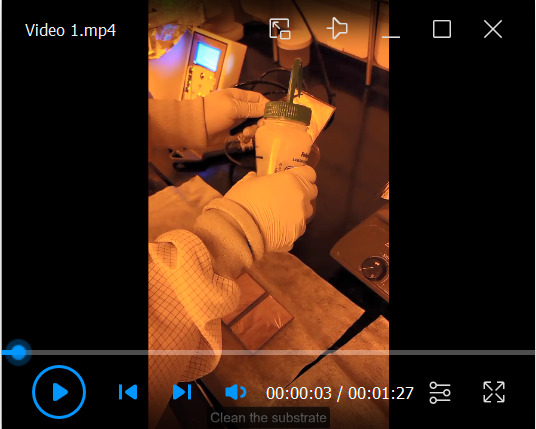
Pattern preparation at cleanroom facility (Video 1)
Prepare a flexible Cu/PI bilayer film, mounted onto a glass slide, and secured by polyimide tape (Figure 1A).
Follow the material cleaning recipe (see Recipe 1).
Deposit a 2.5 μm thickness photoresist layer on the Cu/PI film, using a spin coater.
Bake the sample for 1 min at 105°C.
Wait for the surface of the sample to cool to room temperature for 3 min.
Follow UV lithography and wet-etching recipe (Figure 1B–1C and see Recipe 4).
Follow the material cleaning recipe (see Recipe 1).
-
Electrical components soldering at a standard laboratory facility (Video 2)
Mount components on the pattern, using a soldering machine [Supplementary Figure 1 from previous work ( Kim et al., 2021 )].
Follow the electrical sample cleaning recipe (see Recipe 2).
Use a scalpel to cut the boundary of the sample from the Cu/PI bilayer film (Figure 1F–1H).
Confirm device operation within the wireless power transfer system (Figure 1G).
-
Encapsulation at a standard laboratory facility (Video 2)
Follow PDMS preparation recipe (see Recipe 5).
-
Apply PDMS to the device and remove bubbles using the vacuum oven at room temperature.
Refer to Notes in B section when you make the pre-curved structure (Figure 1H).
Cure the sample in the oven at 80°C for 1 h.
If needed, use a scalpel to trim the boundaries of the sample encapsulated in PDMS.
Perform device quality control before implanting the device in the animal (Figure 1I).
-
The Wireless power transfer system setup
-
Setting up the hardware (Figure 2A):
Connect the power supply to the RF generator (Figure 2B).
Connect the RF generator to the matching board, via the RF cable (Figure 2C).
Attach the antenna to the matching board (Figure 2D). The coil antenna is made of copper sheet (Onlinemetats.com) with dimensions of 1 inch by 30 inch. The antenna is designed so that it resonates at 13.56 MHz. Measuring the antenna using a vector network analyzer allows matching the antenna's resonant frequency at 13.56MHz. Connect capacitors in parallel to the coil, to adjust the resonancy of the antenna.
-
Software manipulation (ISO Start2017 v9.9.10):
Connect the RF generator to the PC, via a USB cable (Figure 3A).
Detect the antenna with “Host mode” (Figure 3B).
Set the TX power level (Figure 3C).
Tune the antenna using the dynamic antenna tuner function, so that the impedance of the antenna is adjusted to 50 Ω at 13.56 MHz (Figure 3D–3E).
Check the tuning status (Figure 3F).
Confirm the wireless power transfer system using a sample device (Figure 3G).
-
-
Nodose ganglion injection ( Calik et al., 2014 )
Under surgical anesthesia (isoflurane, Piramal NDC 66794-017-10), shave the animal’s neck area with a small hair trimmer (Wahl BravMini+).
Administer ketoprofen analgesic subcutaneously.
Sterilize with three alternating scrubs of betadine and alcohol.
Place the animal on its back and lay sterile drape over the neck. The drape should have an opening in the center to allow for incision.
Using saw tooth forceps, lift the skin and make a 1.5 cm midline incision from the clavicle to the jaw area, to expose the neck muscles.
Separate the platysma, sternohyoideus, and omohyoideus muscles using blunt dissection methods, such as inserting a closed scissor tip into the connective tissue and opening the scissors, to break apart the connective tissue. Take care not to damage the carotid artery, as the procedure will be terminal if the artery is nicked.
Utilize magnetic retractors to pull aside the muscle tissue and expose the carotid artery.
The vagus nerve lies inside the carotid sheath. Use a small spatula, to separate the nerve and blood vessel, and a Graefe knife with the other hand, to cut open the sheath.
Trace the nerve up to the jugular foramen. Depending on the animal, the ganglion might lie inside the foramen. Loop a silk suture underneath the nerve, and secure the suture onto a magnetic post. This will help to visualize the ganglion, and provide tension for injecting the virus.
After visualizing the ganglion, inject the virus (200 nL) with a glass micropipette attached to a Nanoject II.
Remove retractors and place muscle tissue back into its original position.
Close the skin with interrupted stitches (use a 6-0 silk suture).
-
Stomach-targeting device implantation (Video 3)
Under surgical anesthesia (isoflurane, Piramal NDC 66794-017-10), shave the animal’s ventral side with a small hair trimmer (Wahl BravMini+).
Administer ketoprofen analgesic subcutaneously.
Sterilize with three alternating scrubs of betadine and 70% isopropyl alcohol.
Place the animal on its back and lay sterile rodent surgical drapes over its abdomen. The drape should have an opening in the center to allow for incision.
Using Graefe forceps, lift the skin and make a 2 cm incision along the abdominal midline to expose the abdominal muscle tissue.
Lift the muscle layer using Graefe forceps and snip open a small hole. While holding up the abdominal muscle with forceps, insert scissors with ball tip (to avoid damage to the underlying tissue) and make an incision from the mid-abdomen extending to the xiphoid cartilage (Figure 4A).
Pull the stomach outside of the abdomen using ring forceps, and place the stomach onto gauze soaked with sterile saline. This keeps the stomach hydrated.
Utilize retractors to keep the incision site open.
Puncture two adjacent holes in the stomach fundus using a 32-G needle. The holes need to be within several millimeters of each other. Enough tissue is needed for suturing around the LED tether entry and exit, but not too far apart which could restrict stomach expansion.
Thread the LED tether in one hole and out the other, using fine-tipped Dumont forceps (Figure 4B). Blunt, flat-tipped forceps are also useful for handling the tether during this step.
With the µLED inside the stomach, secure the tether in place with purse-string sutures (5-0 PGA) (Figure 4C).
Ensure that the implantation area will not come into contact with the liver, otherwise the liver will form scar tissue and fuse with the surgical area.
Place the device harvester in the lower abdominal cavity and place the stomach back into its normal orientation.
Close the abdominal wall with interrupted stitches using absorbable suture (PGA 3-0 sutures) and the skin with non-absorbable suture (Nylon 4-0 sutures) (Figure 4D).
Mice receive analgesics during the surgery and daily post-operative care.
Video 4. Post-surgery validation.
Download video file (3MB, mp4)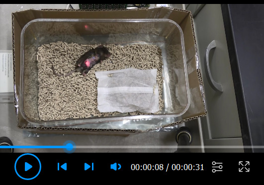
-
Troubleshooting
-
When bleeding occurs:
We implant the device away from blood vessels and do not encounter excessive bleeding. If there is blood, it is minimal and it can be cleaned with a sterile cotton tip. Defining a typical successful surgery encompasses the animal being returned to a cage and no postoperative complications or animal deaths occur.
We have not previously experienced severe complications with stomach implants. As with any surgical procedure, it is advisable to monitor body weights for 7–10 days postoperatively. Analgesics are provided during the surgery and daily if the animals lose weight or exhibit discomfort. We euthanize mice if they fall below 80% of their starting body weight.
-
Rate of animal deaths during surgery and after post-surgery:
Success rate is virtually 100% for stomach implants (video 4). The most severe procedure is the injection of a virus into the nodose ganglion. We recommend injecting the virus during a separate surgical procedure. The most common cause of death is bleeding during the surgery, if a blood vessel is punctured. There is a high survival rate (95%) if the mouse wakes up from a unilateral virus injection surgery and care is taken to not damage neck muscles. There is about a 15-20% mortality rate with bilateral virus injections. We believe this is due to bilateral nerve damage and breathing difficulty.
-
Video 1. Fabrication of the device substrate.
Video 2. Device fabrication.
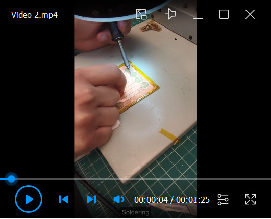
Figure 2. Hardware setup for wireless power transfer system.

A. Components of the wireless power TX system. B. Power supply connection for the RF generator. C. Connection between the RF generator and matching board via RF coax cable. D. Attach the TX antenna to the matching board.
Figure 3. Software manual.
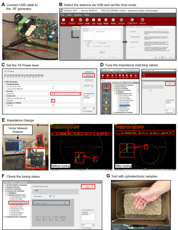
A. First, connect the RF generator to the PC for control via the software. B. Detect the antenna for powering via the RF generator. C. Set the TX power level. D. Perform antenna tunning to adjust impedance to 50 Ω, for maximum power transmission. E. Confirm impedance of 50 Ω with the vector network analyzer. F. Check the tuning status. G. Place the device in the cage (wireless power transfer system) and confirm light illumination from the device.
Video 3. Surgery procedure.
(This video was made at Baylor College of Medicine. All animal care and experimental procedures were approved by the Institutional Animal Care and Use Committees at Baylor College of Medicine under protocol AN-6598.)
Figure 4. Step-by-step procedures for device implantation.

A. Stomach exposal for the tether insertion. B. Conceptual illustration of insertion of the gastric optoelectronic device into the stomach. C. Insertion of the tether, including μLED, into the stomach. D. Checking the device operation after implantation surgery.
Data analysis
-
Device test at a standard laboratory facility
Turn on the wireless power transfer system.
Check the device operation at all positions and heights in the cage [Supplementary Figures 11 and 12 from previous work ( Kim et al., 2021 )].
-
Device quality control at a standard laboratory facility
Follow device test step (1st test).
Immerse the device in 10% PBS solution for 24 h [Supplementary Figure 6 from previous work ( Kim et al., 2021 )].
Follow device test step under this immersion condition (2nd test).
After the electrical sample cleaning recipe, follow the device test step (3rd test).
-
Device operation in an animal model
Turn on the wireless power transfer system.
Place a device-implanted animal into a cage.
Check the indicator LED in the abdominal cavity.
Experimental results are in Figures 3 and 4 from previous work ( Kim et al., 2021 ).
-
Proof of virus expression
After experiments, anesthetize (Beuthanasia, 320 mg/kg, delivered intraperitonially) mice and perform intracardiac perfusion with 1× PBN or saline, not with heparin or EDTA ( Gage et al., 2012 ), followed by 4% paraformaldehyde.
Extract the brain, nodose ganglion, and stomach, post-fix in 4% paraformaldehyde overnight, and cryoprotect in PBS containing 30% sucrose, until the tissues sink to the bottom in the sucrose solution.
Collect coronal cryostat sections for the brain, nodose ganglion, and stomach tissues (30, 20, and 10 μm thick), and mount them directly onto microscope slides.
Coverslip samples using DAPI Fluoromount-G mounting medium (SouthernBiotech).
Experimental results are in Figures 3c-e from previous work ( Kim et al., 2021 ).
Notes
-
Soldering of electrical components
Apply solder wires onto the pads of the pattern.
Attach the components to the pads using a small amount of solder flux and solder wires.
Before covering the tether with a sandwich Cu/PI film layer, make a tiny hole with a scalpel near the μLED position, for defined μLED illumination.
Encapsulation of pre-curved structure
Hold the device using clips, to shape the device as a pre-curved design; then, apply a small amount of PDMS using a pipet tip (Figure 1H).
Cure the tether part, including the pre-curved structure near the μLED.
Dip the rest of the device into the PDMS, and then cure it in the oven.
Recipes
-
Material cleaning
Rinse with acetone for 10 s.
Rinse with methanol for 10 s.
Rinse with isopropanol for 20 s.
Rinse with distilled water (Singly Distilled, Laboratory Grade) for 1 min.
Dry samples on the hot plate at 105°C until fully dried.
-
Electrical sample cleaning
Immerse the sample in isopropanol for 5 min.
Immerse the sample in distilled water for 5 min.
Rinse with distilled water for 1 min.
Dry samples in the oven at 80°C until fully dried.
-
Photoresistor spin coating
Place 1 mL of photoresist onto the center of the substrate without bubbles.
Spin-coat at 4,000 r.p.m. for 20 s.
-
UV-lithography and wet-etching
Align the sample and the pattern mask carefully.
Illuminate with 100 mJ/cm2 intensity-UV lights to lithograph patterns for pads and interconnections.
Immerse in the developer for 20 s, and wash with distilled water.
Immerse in the copper etchant for 7 min.
Follow the material cleaning recipe.
-
PDMS preparation
Mix the PDMS kit gently at a 10:1 ratio.
Place the mixed PDMS in a vacuum oven at room temperature, until all the bubbles have been removed.
Vent the air to normal pressure values.
Acknowledgments
This work was supported by grants from the interdisciplinary X-Grants Program, part of the President’s Excellence Fund at Texas A&M University, 2018 NARSARD Young Investigator Awards from Brain & Behavior Foundation, and National Science Foundation Engineering Research Center for Precise Advanced Technologies and Health Systems for Underserved Populations (PATHS-UP; EEC-164851). We thank Dr. Carlos Campos from the University of Washington for in vivo experiments. This protocol was adapted from previous work ( Kim et al., 2021 ).
Competing interests
The subject matter of the manuscript is protected by Texas A&M Technology Commercialization (TTC) Ref. & Title (5687TEES21, Implantable Devices and Techniques for the Treatment of Obesity).
Ethics
All animal care and experimental procedures were approved by the Institutional Animal Care and Use Committees at Baylor College of Medicine under protocol AN-6598.
Citation
Readers should cite both the Bio-protocol article and the original research article where this protocol was used.
Q&A
Post your question about this protocol in Q&A and get help from the authors of the protocol and some of its users.
References
- 1. Berthoud H. R.(2008). The vagus nerve, food intake and obesity. Regul Pept 149(1-3): 15-25. [DOI] [PMC free article] [PubMed] [Google Scholar]
- 2. Berthoud H. R. and Neuhuber W. L.(2000). Functional and chemical anatomy of the afferent vagal system. Auton Neurosci 85(1-3): 1-17. [DOI] [PubMed] [Google Scholar]
- 3. Caggiano V., Cheung V. C. K. and Bizzi E.(2016). An optogenetic demonstration of motor modularity in the mammalian spinal cord. Sci Rep 6: 35185. [DOI] [PMC free article] [PubMed] [Google Scholar]
- 4. Calik M. W., Radulovacki M. and Carley D. W.(2014). A method of nodose ganglia injection in Sprague-Dawley rat. J Vis Exp e52233. [DOI] [PMC free article] [PubMed] [Google Scholar]
- 5. Deisseroth K.(2011). Optogenetics. Nat Methods 8(1): 26-29. [DOI] [PMC free article] [PubMed] [Google Scholar]
- 6. Deisseroth K.(2015). Optogenetics: 10 years of microbial opsins in neuroscience. Nat Neurosci 18(9): 1213-1225. [DOI] [PMC free article] [PubMed] [Google Scholar]
- 7. Gage G. J., Kipke D. R. and Shain W.(2012). Whole animal perfusion fixation for rodents. J Vis Exp(65): 3564. [DOI] [PMC free article] [PubMed] [Google Scholar]
- 8. Gutruf P., Yin R. T., Lee K. B., Ausra J., Brennan J. A., Qiao Y., Xie Z., Peralta R., Talarico O., Murillo A., et al.(2019). Wireless, battery-free, fully implantable multimodal and multisite pacemakers for applications in small animal models. Nat Commun 10(1): 5742. [DOI] [PMC free article] [PubMed] [Google Scholar]
- 9. Hibberd T. J., Feng J., Luo J., Yang P., Samineni V. K., Gereau R. W. 4th., Kelley N., Hu H. and Spencer N. J.(2018). Optogenetic Induction of Colonic Motility in Mice. Gastroenterology 155(2): 514-528 e516. [DOI] [PMC free article] [PubMed] [Google Scholar]
- 10. Kim T. I., McCall J. G., Jung Y. H., Huang X., Siuda E. R., Li Y., Song J., Song Y. M., Pao H. A., Kim R. H., et al.(2013). Injectable, cellular-scale optoelectronics with applications for wireless optogenetics. Science 340(6129): 211-216. [DOI] [PMC free article] [PubMed] [Google Scholar]
- 11. Kim W. S., Hong S., Gamero M., Jeevakumar V., Smithhart C. M., Price T. J., Palmiter R. D., Campos C. and Park S. I.(2021). Organ-specific, multimodal, wireless optoelectronics for high-throughput phenotyping of peripheral neural pathways. Nat Commun 12(1): 157. [DOI] [PMC free article] [PubMed] [Google Scholar]
- 12. de Lartigue G.(2016). Role of the vagus nerve in the development and treatment of diet-induced obesity. J Physiol 594(20): 5791-5815. [DOI] [PMC free article] [PubMed] [Google Scholar]
- 13. Maimon B. E., Zorzos A. N., Bendell R., Harding A., Fahmi M., Srinivasan S., Calvaresi P. and Herr H. M.(2017). Transdermal optogenetic peripheral nerve stimulation. J Neural Eng 14(3): 034002. [DOI] [PubMed] [Google Scholar]
- 14. Maimon B. E., Diaz M., Revol E. C. M., Schneider A. M., Leaker B., Varela C. E., Srinivasan S., Weber M. B. and Herr H. M.(2018). Optogenetic Peripheral Nerve Immunogenicity. Sci Rep 8(1): 14076. [DOI] [PMC free article] [PubMed] [Google Scholar]
- 15. Mickle A. D., Won S. M., Noh K. N., Yoon J., Meacham K. W., Xue Y., McIlvried L. A., Copits B. A., Samineni V. K., Crawford K. E., et al.(2019). A wireless closed-loop system for optogenetic peripheral neuromodulation. Nature 565(7739): 361-365. [DOI] [PMC free article] [PubMed] [Google Scholar]
- 16. Montgomery K. L., Yeh A. J., Ho J. S., Tsao V., Mohan Iyer S., Grosenick L., Ferenczi E. A., Tanabe Y., Deisseroth K., Delp S. L., et al.(2015). Wirelessly powered, fully internal optogenetics for brain, spinal and peripheral circuits in mice. Nat Methods 12(10): 969-974. [DOI] [PMC free article] [PubMed] [Google Scholar]
- 17. Montgomery K. L., Iyer S. M., Christensen A. J., Deisseroth K. and Delp S. L.(2016). Beyond the brain: Optogenetic control in the spinal cord and peripheral nervous system. Sci Transl Med 8(337): 337rv335. [DOI] [PubMed] [Google Scholar]
- 18. Park S. II., Shin G., Banks A., McCall J. G., Siuda E. R., Schmidt M. J., Chung H. U., Noh K. N., Mun J. G., Rhodes J., et al.(2015). Ultraminiaturized photovoltaic and radio frequency powered optoelectronic systems for wireless optogenetics. J Neural Eng 12(5): 056002-056002. [DOI] [PMC free article] [PubMed] [Google Scholar]
- 19. Park S. II., Brenner D. S., Shin G., Morgan C. D., Copits B. A., Chung H. U., Pullen M. Y., Noh K. N., Davidson S., Oh S. J., et al.(2015). Soft, stretchable, fully implantable miniaturized optoelectronic systems for wireless optogenetics. Nat Biotechnol 33(12): 1280-1286. [DOI] [PMC free article] [PubMed] [Google Scholar]
- 20. Park S. Il, Shin G., McCall J.G., Al-Hasani R., Norris A., Xia L., Brenner D.S., Noh K.N., Bang S.Y., Bhatti D.L., et al.(2016). Stretchable multichannel antennas in soft wireless optoelectronic implants for optogenetics. Proc Natl Acad Sci 113(50): E8169-E8177. [DOI] [PMC free article] [PubMed] [Google Scholar]
- 21. Shin G., Gomez A. M., Al-Hasani R., Jeong Y. R., Kim J., Xie Z., Banks A., Lee S. M., Han S. Y., Yoo C. J., et al.(2017). Flexible Near-Field Wireless Optoelectronics as Subdermal Implants for Broad Applications in Optogenetics. Neuron 93(3): 509-521 e503. [DOI] [PMC free article] [PubMed] [Google Scholar]
- 22. Towne C., Montgomery K. L., Iyer S. M., Deisseroth K. and Delp S. L.(2013). Optogenetic control of targeted peripheral axons in freely moving animals. PLoS One 8(8): e72691. [DOI] [PMC free article] [PubMed] [Google Scholar]
- 23. Williams E. K., Chang R. B., Strochlic D. E., Umans B. D., Lowell B. B. and Liberles S. D.(2016). Sensory Neurons that Detect Stretch and Nutrients in the Digestive System. Cell 166(1): 209-221. [DOI] [PMC free article] [PubMed] [Google Scholar]