

Abstract
Maximum power point tracking (MPPT) is an effective method to improve the power generation efficiency and power supply quality of a proton exchange membrane fuel cell (PEMFC). Due to the inherent nonlinear characteristics of PEMFC, conventional MPPT methods are often difficult to achieve a satisfactory control effect. Considering this, artificial bee colony algorithm combining fuzzy control (ABC-fuzzy) was proposed to construct a MPPT control scheme for PEMFC. The global optimization ability of ABC algorithm was used to approach the maximum power point of PEMFC and solve the problem of falling into local optimization, and fuzzy control was used to eliminate the problems of large overshoot and slow convergence speed of ABC algorithm. The testing results show that compared with perturb & observe algorithm, conductance increment and ABC methods, ABC-fuzzy method can make PEMFC obtain greater output power, faster regulation speed, smaller steady-state error, less oscillation and stronger anti-interference ability. The MPPT scheme based on ABC-fuzzy can effectively realize the maximum power output of PEMFC, and plays an important role in improving the service life and power supply efficiency of PEMFC.
Subject terms: Energy science and technology, Engineering, Mathematics and computing
Introduction
About 85% of the energy needed for human survival and development comes from fossil fuels, which are 57% of the global carbon emission sources1. To achieve sustainable development, more and more attention has been paid to the development and utilization of renewable and clean energy2.
As a kind of power generation equipment that directly converts chemical energy into electric energy, fuel cell is considered to be one of the most potential green energies. Among them, proton exchange membrane fuel cell (PEMFC) is the best alternative to traditional power supply due to its advantages of simple structure, fast start, high power density, low noise, zero pollution and so on3–5. PEMFC has great application potential in electric vehicles, distributed power generation, portable power system, islanded microgrid, aerospace equipment, etc., and plays an important role in alleviating environmental pressure and rebuilding energy consumption structure because of its outstanding environment-friendly characteristics6,7. However, its disadvantages such as short service life, fast performance decay and high maintenance cost have not been well solved, which hinder their further wide popularization and applications8,9.
Advanced control technology is an alternative solution to improve the overall performance of an energy system. Among them, the Maximum power point tracking (MPPT) algorithm is recognized as an effective method to solve the problem of power output efficiency of power generation system, which has been widely used in photovoltaic power generation system (PV)10–13, wind power generation system14,15, and wind solar hybrid power system16. In recent years, the application of MPPT in fuel cell system has been reported17–19.
The output characteristics of PEMFC are nonlinear, which are affected by temperature, oxygen partial pressure, hydrogen partial pressure, membrane water content, stoichiometry, etc. However, under each specific condition, the PEMFC has only one unique working point corresponding to the maximum power point (MPP)20. Therefore, tracking and stable operation at the maximum power point is very important to improve the energy efficiency of PEMFC.
The commonly used MPPT methods mainly include constant voltage (CVT), perturb & observe algorithm (P&O), conductance increment (INC), hill climbing (HC), etc.21. P&O is usually used to track the maximum power of PEMFC, but the tracking speed is slow and misoperation is easy to occur in the case of sudden changes22. Ahmadi et al. proposed an MPPT for PEMFC based on the particle swarm optimization (PSO) and PID controller (PSO-PID), but there are problems of local optimization and too slow optimization speed23. Harrag et al. addressed a variable step fuzzy based MPPT controller, but the setting of fuzzy rules and proportional quantization factors needed the support of practical experience24. Harrag et al. proposed a single sensor variable step size MPPT method for PEMFC, although the steady state performance could meet the demand, the dynamic performance was not particularly satisfactory25. Liu et al. designed a fractional order high pass filter (FOHPF) to improve traditional extremum seeking control (ESC), but the response speed was difficult to guarantee26. In the past decade, there has been a great development of maximum power point tracking controllers for fuel cell power systems. Mallick et al. proposed an adaptive hybrid controller based on artificial neural network (ANN), which successfully tracked MPP with less oscillation under variable temperature27. Fathy et al. proposed a strategy based on salp swarm algorithm (SSA), which has high reliability and high efficiency when extracting the maximum power of PEMFC28. Souissi used an adaptive sliding mode controller for MPPT of PEMFC and chattering reduction of 85% has been achieved29.
Compared to the difficulty of improving the efficiency of a converter or the conversion rate of a PEMFC, using some advanced control strategy to improve the efficiency of MPPT control is a relatively simple, fast and more efficient way30,31. However, the commonly used MPPT methods still have some problems, such as slow tracking speed, large steady-state fluctuation, poor anti-interference ability, etc., which need to be further improved to raise the tracking accuracy and speed.
In recent years, evolutionary algorithms (EAs) have been used for optimization problems. EA is a global search optimization technique based on biological evolution mechanisms such as natural selection and genetic variation, mainly including genetic algorithm (GA), particle swarm optimization (PSO), ant colony optimization (ACO), gray wolf optimization (GWO), cuckoo search (CS), artificial bee colony (ABC)32–34, etc. Since the EAs are stochastic search algorithms, their probability of finding approximate best solutions from finite set of solution space at the early stage of the optimization process is very high. Ma et al. proposed a new large-scale multi-objective EA to solve the large-scale multiobjective and many-objective optimization problems35. An orthogonal learning framework for brain storm optimization (OLBSO) was proved very powerful in optimizing complex functions36. Younas et al. introduced EA to solve the sensor selection problem in Internet of Thing (IoT) systems37. There have been many studies on EAs for gene selection and detection of fatal diseases38–41. EAs were also used for reservoir operation42, dynamic optimization of biodiesel production process43, vehicle route planning44, traffic signal control45, assembly line balancing46, MPPT of hybrid renewable energy system47, etc. EAs will play an increasingly important role in solving practical optimization problems in a wide range of science and engineering48, and it provides a broader idea for MPPT control of PEMFC.
Among EAs, ABC is an optimization algorithm based on the intelligent behavior of honey bee swarm49. Compared with other algorithms based on swarm intelligence and population such as GA, PSO and Particle Swarm Inspired Evolutionary Algorithm (PS-EA), ABC has the advantages of relative simplicity, strong robustness, fast convergence, fewer setting parameters and high flexibility, and is considered to be an excellent global optimization algorithm50–54. In view of these advantages, ABC has been applied to numerous benchmark problems and real-world problems55. Zirkohi employed ABC algorithm to optimize the parameters of the two fractional-order PI controllers of induction motor and achieved better control effect56. Zhu et al. used ABC algorithm in solving examination and course timetabling problems, which significantly reduced computational costs57. Chen et al. introduced ABC algorithm in optimization of transfer station selection and train timetables for road–rail intermodal transport network58.
In consideration of the advantages of simplicity and robustness of ABC algorithm, it was selected to design a new MPPT scheme for PEMFC. In order to overcome the defects such as large overshoot during startup in ABC, this paper proposed a hybrid ABC algorithm integrated with fuzzy control (ABC-fuzzy) for MPPT control of PEMFC to solve the problem of accurate maximum power tracking, and its control effect was compared with the traditional P&O algorithm, variable step INC and common ABC. ABC-fuzzy algorithm has faster tracking speed, smaller steady-state error and stronger anti-interference ability, which effectively improves the MPPT control effect of PEMFC.
Mathematical model of PEMFC
PEMFC is a kind of electrochemical device, which can directly convert the chemical energy of fuel (hydrogen) and oxidant (oxygen) into electrical energy. The main components of PEMFC are anode, cathode and proton exchange membrane. The hydrogen is decomposed into protons and electrons in the anode. The protons move to the cathode through the proton exchange membrane and react with oxygen in the cathode to form water, while the electrons are transferred to the cathode through an external circuit and thus the terminal voltage is produced.
The stack total voltage can be represented by a controlled voltage source in series with a constant resistance59. The controlled voltage source (E) is described by:
| 1 |
in which Eoc is the open circuit voltage (V); N is the number of cells; A is the Tafel slope (V); io is the exchange current (A); Td is the response time (at 95% of the final value) (sec); and iFC denotes the output current (A).
The output voltage of the PEMFC stack can be described as:
| 2 |
where Rohm is the internal resistance (Ω); UFC denotes the output voltage (V).
Eoc, io and A are described as follows:
| 3 |
| 4 |
| 5 |
where En is the Nernst voltage (V); Kc is the voltage constant at nominal condition of operation; R is a gas constant (J/(mol K)); F is the Faridy's constant (s/mol); z is the number of moving electrons; k is Boltzmann’s constant (J/K); h is Planck’s constant (Js); PH2 is the partial pressure of hydrogen inside the stack (bar); PO2 is the partial pressure of oxygen inside the stack (bar); ∆G is the activation energy barrier (J); T is the operating temperature (K), and α is the charge transfer coefficient.
The partial pressures and the Nernst voltage can be calculated by:
| 6 |
| 7 |
| 8 |
where x denotes the percentage of hydrogen in the fuel (%); y denotes the percentage of oxygen in the oxidant (%); PFuel denotes the absolute supply pressure of fuel (bar); PAir denotes the absolute supply pressure of air (bar); λH2 and λO2 are the conversion rates of hydrogen and oxygen that can be represented as:
| 9 |
| 10 |
where QFuel denotes the fuel flow rate (L/min); QAir denotes the air flow rate (L/min).
The output power used to measure the power supply capacity of a PEMFC stack can be calculated as follows:
| 11 |
A simulation module of 6 kW fuel cell stack built according to the above model is used to simulate the PEMFC stack in this study. The main parameters are shown in Table 1. The output power curves of PEMFC with the change of load resistance under two different temperature conditions are shown in Fig. 1.
Table 1.
Main parameter used the model.
| Symbol | Physical meaning | Value | Unit |
|---|---|---|---|
| F | Faridy's constant | 96,485 | As/mol |
| PAir | Air pressure | 1 | bar |
| R | gas constant | 8.3145 | J/(molK) |
| A | The battery area | 0.0240 | m2 |
| z | moving electrons | 2 | – |
| k | Boltzmann’s constant | 1.38 × 10⁻²³ | J/K |
| h | Planck’s constant | 6.626 × 10⁻³⁴ | Js |
| y | Oxygen concentrations | 21 | % |
| x | Hydrogen concentration | 99.95 | % |
| N | Number of Batteries | 65 | – |
| PFuel | Fuel pressure | 1.5 | bar |
Figure 1.
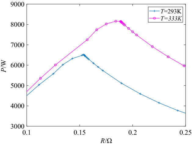
P-R characteristics of the used PEMFC.
It can be clearly seen from the curves in Fig. 1 that there is indeed an obvious peak on each operation curve, which indicates that the maximum power point is inevitable. According to the relevant circuit knowledge, the output power of a power supply reaches its maximum value when the the load resistance is equal to its internal resistance. It can be seen that when operating at 333 K, the maximum output power (Pmax) value of the PEMFC is about 8162 W, and the load resistance at the maximum power is about 0.18 Ω, which means that the internal resistance of the PEMFC at 333 K is about 0.18 Ω. When the temperature changes to 293 K under the same other conditions, the maximum output power is about 6520 W and the corresponding internal resistance is about 0.15 Ω. As long as the external load resistance can always be equal to the internal resistance through effective methods, this maximum power point will be tracked in real time to keep the PEMFC at maximum power output all the times.
In addition, it can also be seen from the P-R curves that temperature has an impact on the output power of PEMFC. The maximum output power and internal resistance of a PEMFC are different at different temperatures.
Scheme design of MPPT
Structure of control system
Figure 2 displays the diagrammatic sketch of the MPPT control system of PEMFC with Boost converter, which is mainly composed of PEMFC, boost converter, MPPT controller, PWM generator and external load resistance. Because the Boost converter has the advantages of simple structure, easy control and voltage amplification, it is used in the system to improve the output voltage and as a regulator to realize the MPPT control scheme. The output of PWM generator is a series of square waves with different duty cycle, which is used to control the ON and OFF of the Boost convertor. The output duty cycle of the PWM controller is represented by D.
Figure 2.
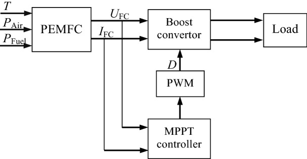
Diagram of MPPT control system of PEMFC.
For the system shown in Fig. 2, the equivalent load resistance of PEMFC can be expressed according to the knowledge of power electronic technology as:
| 12 |
in which Req is the equivalent load resistance of PEMFC, and RL denotes the actual load resistance, that is, the load resistance at the output of the Boost converter.
It is well known that the output power of an electric source can reach its maximum if and only if its external resistance is equal to its internal resistance. According to Eq. (12), the purpose of adjusting the equivalent load resistance can be achieved by adjusting the duty cycle of the Boost converter. Therefore, by adjusting the duty cycle, the equivalent load resistance of PEMFC can be equal to its internal resistance, so as to achieve the purpose of maximum power output.
P&O algorithm
P&O is the most widely used MPPT method at present. Its basic principle is to apply a positive disturbance voltage to the fuel cell, sample its output voltage and current, and calculate the change rate of its voltage and power. If the output power increases after the disturbance, it indicates that the direction of the disturbance voltage is the direction of the increase of the power output, and the disturbance should be continued in this direction; otherwise, the disturbance should be in the opposite direction. According to the changing direction of voltage and power, the disturbance voltage is continuously applied to the fuel cell until the maximum output power is approached gradually, so as to realize the MPPT. The flowchart of P&O algorithm is shown in Fig. 3, in which “k” denotes the sampling point, stands for the increment of duty cycle.
Figure 3.

Flow chart of P&O algorithm of MFC.
P&O has the advantages of simple calculation and convenient implementation, but it can only keep the system oscillating infinitely near the maximum power point, and can not accurately track the maximum power point, so it can not effectively solve the problems of tracking accuracy and speed.
Variable step INC MPPT
The incremental conductance (INC) method determines whether the maximum power point is tracked according to the slope of the voltage–power curve of PEMFC. If dP/dU = 0, the operating point is at the maximum power point and the operating voltage needs to be kept unchanged; if dP/dU < 0, the working point is on the right side of the maximum power point, and the working voltage needs to be reduced; if dP/dU > 0, the working point is on the left side of the maximum power point, and the working voltage needs to be increased.
When the INC method is used for MPPT, the tracking speed of the system is determined by the step size. When the step size is large, the tracking speed is fast, but it is difficult to keep it after reaching the maximum power point, and it is easy to produce concussion. On the contrary, when the step size is small, the tracking is stable after reaching the maximum power point, but the tracking speed is relatively slow. The step size selection needs to balance tracking speed and tracking accuracy, so it is very difficult to select appropriate step size.
By observing the voltage–power curve, a variable step size method is proposed. Considering the MPPT control system shown in Fig. 2, the duty cycle of Boost converter is adjusted by the following formula:
| 13 |
where D(k) represents the duty cycle of the boost converter at the sampling time k; υ is the speed factor used for adjusting the step size. To ensure the convergence of the MPPT update rule, the speed factor must satisfy the following relationship:
| 14 |
where Δdmax indicates the maximum change of duty cycle in the previous sampling period.
When Eq. (14) is satisfied, the system can work in variable step mode, and the greater the υ, the faster the response60,61. If Eq. (14) cannot be satisfied, the system will work with the constant step of Δdmax. The variable step size INC (VS-INC) can effectively improve the tracking speed and accuracy, but the selection of speed factor and Δdmax is specific, so different speed factors and Δdmax need to be set in different cases, otherwise the tracking effect will fail to meet the requirements, resulting in the tracking dead zone.
ABC-based MPPT
Artificial Bee Colony (ABC) algorithm is an optimization algorithm inspired by honeybee's nectar gathering behavior and designed based on random population. Because of its simplicity, efficiency, robustness and global search capability, it is proved to be one of the most effective naturally-inspired algorithms for dealing with unconstrained and constrained single-objective or multi-objective global optimization problems.
In the ABC algorithm, all the bees are divided into three groups: employed bees, onlookers and scouts. The three kinds of honeybees exploit nectar sources through division of labor and cooperation, and constantly update the location of nectar sources through marking and sharing to find the optimal nectar sources. The location of the nectar source corresponds to the feasible solution of the optimization problem, and the quality of the nectar source is measured by the fitness value of the optimization problem. The main process of ABC algorithm includes62–65:
(1) Initialization stage Set the number of various bee colonies, optimization range, dimension and maximum iterations.
When ABC algorithm is used to optimize the duty cycle D in this study, the initial number of the employed bees and onlooker bees are set to be 50 and 30 respectively, the dimension is set to 1, the maximum number of iterations is set to 10, and the optimization range is set as (0.85, 1).
(2) Employed bee phase The employed bees searched for a new food source near their current food source.
To produce a candidate food position from the old one, the new solution is compared with the current solution, and the fitness is calculated according to the following formula:
| 15 |
where Vij denotes the new location of food source; Xij denotes the current food source; i {1, 2,…, SN} is the position of the food source; k {1, 2,…, SN} and j {1, 2,…, M} are randomly chosen indexes, SN is the number of solutions in the colony (that is, the size of the swarm), M is the dimension of the problem; and φij is a random number in the range [− 1,1].
(3) Onlooker bee phase The onlookers choose the food source after sharing information of employed bees and determine the amount of nectar. Some better solutions are selected according to a probability which is computed by:
| 16 |
in which fi is the fitness function value of the ith solution.
(4) Scout bee phase In each iteration, the scout bees monitor the changes of each solution in the swarm. If a food source cannot be updated through a predetermined cycle, it will be removed from the population and the employed bees of the food source will become scout, and they use the following equation to find a new random food source location:
| 17 |
ABC-Fuzzy MPPT
Although ABC shows good search performance, it still has the disadvantages of slow convergence speed and low solving accuracy66. To solve these problems, a MPPT scheme based on ABC algorithm integrated with fuzzy control (ABC-fuzzy) is proposed. The structure diagram of the ABC-fuzzy MPPT control system is shown in Fig. 4.
Figure 4.

Structure diagram of ABC-fuzzy MPPT.
The integral of power multiplied by time is introduced as the intermediate variable as shown in the following formula:
| 18 |
where W is the electric energy produced by the fuel cell. In the same time period, the greater the power generation energy W, the greater the output power P. Therefore, it is used as the fitness to compare and judge the choice of duty cycle.
The power error ΔP and the voltage error ΔU are respectively used as the inputs of the fuzzy controller, and its output is used as one of the components (Dn) of the duty cycle. The basic domain of ΔP and ΔU are designed as [− 100, 100] and [− 10, 10], respectively; and the basic domain of Dn is designed as [− 8, 8]. In order to achieve good control effect, the fuzzy domains of ΔP and ΔU are divided into five fuzzy subsets, namely {NB, NS, ZE, PS, PB}, and the fuzzy domains of Dn are divided into seven fuzzy subsets, namely {NB, NM, NS, ZE, PS, PM, PB}.
The detailed steps of ABC-fuzzy algorithm are shown in Table 2, and the fuzzy control rules are designed as shown in Table 3.
Table 2.
Steps for ABC-fuzzy algorithm.
| Operation | |
|---|---|
| Step 1 |
Initialization: Employed bees = 30 Onlooker bees = 20 Dimension = 1 Maximum iterations = 10 Optimization range = (0.85,1) Initialize population parameters D1…Dr Take a random number in D1…Dr as the output Dm |
| Step 2 | Call Dm and Dn, the output of the fuzzy controller for superposition, and its output is used to adjust the duty cycle to D. Measure UFC and IFC, calculate the energy W, and use it as the fitness value corresponding to Dm in ABC |
| Step 3 |
Employed Bee Phase: Update Dm according to Eq. (15) and repeat step 2 |
| Step 4 | Compare the fitness. If the fitness is better, update the optimal Dm and the optimal fitness, otherwise update the stagnation times |
| Step 5 | The probability of selecting Dm is calculated by roulette |
| Step 6 |
Onlooker bee phase: Select Dm according to probability, and generates a new Dm according to Eq. (15) |
| Step 7 | Repeat steps 2 and 4 to update Dm continuously according to the greedy strategy |
| Step 8 |
Scout bee phase: Compare the stagnation times. If it exceeds the limit, select a new Dm according to Eq. (17) to replace the overrun Dm |
| Step 9 | Repeat step 2 and record the updated Dm and fitness |
| Step 10 | Evaluate Dm. If Dm meets the optimal condition, then end the cycle, otherwise return to step 3 |
Table 3.
The designed fuzzy rules.
| ΔP | ||||||
|---|---|---|---|---|---|---|
| NB | NS | ZE | PS | PB | ||
| ΔU | NB | PB | PM | NS | NM | NB |
| NS | PM | PS | NS | NS | PM | |
| ZE | NM | NS | ZE | PS | PM | |
| PS | NM | NS | PS | PS | PM | |
| PB | NB | NM | PS | PM | PB | |
System simulation
A simulation model of MPPT control system of PEMFC with the structure shown in Fig. 2 was established in MATLAB simulation environment. In this simulation, the rated power of the PEMFC was 6 kW, and the load resistance was RL = 70 Ω. The main parameters of the Boost converter were as follows: the inductor was L = 3 mH and the capacitor was C = 0.47 mF, and the sampling frequency was 20 kHz.
Four MPPT control algorithms, including P&O, variable step INC (VS-INC), ABC and ABC-Fuzzy, were applied to this PEMFC system respectively. In order to facilitate the comprehensive performance evaluation of the controlled PEMFC system, these different control schemes were tested under the conditions of temperature change and inlet pressure change respectively.
Operation under inlet pressure variation
In this test, the operating temperature of the PEMFC system was kept at 333 K but the inlet fuel pressure and air pressure jumped from the initial value of 0.5 bar to 1.5 bar and 0.5 bar to 1 bar respectively at 0.15 s. Under such conditions, the main performance indexes are listed in Table 4, and the output power variation curves of the PEMFC systems with different control schemes are shown in Fig. 5. In Table 4, Str denotes the tracking speed (s); PS denotes the steady output power (W); Omax denotes the maximum overshoot (W); ASA denotes the steady amplitude (W); and Fl denotes fluctuation (%).
Table 4.
Experimental data under pressure change.
| Algorithm | Str | PS | Omax | ASA | Fl |
|---|---|---|---|---|---|
| P&O | 0.09 | 7210 | 2785 | 269 | 37.3 |
| VS-INC | 0.10 | 7242 | 919 | 101 | 1.39 |
| ABC | 0.13 | 7311 | 3848 | 102 | 1.40 |
| ABC-fuzzy | 0.03 | 7524 | 257 | 93 | 1.24 |
Figure 5.

Power curves under pressure change.
It can be seen that, among the four different MPPT control algorithms, ABC-fuzzy algorithm obtained the fastest tracking speed, maximum output power, weakest amplitude fluctuation and minimum steady-state error. In the start-up stage, the tracking speed of P&O, VS-INC, ABC and ABC-fuzzy algorithm were 0.09 s, 0.10 s, 0.13 s and 0.03 s respectively, that is, the tracking speed of ABC-fuzzy was 67%, 70% and 77% faster than that of P&O, VS-INC and ABC respectively. The ABC algorithm had the slowest tracking speed and biggest overshoot in the start-up stage, which further confirmed its defect of "slow convergence speed" mentioned above, and also proved that it is not feasible to use ABC algorithm alone for MPPT control. The ABC-fuzzy algorithm not only improved the tracking accuracy, but also greatly reduced the tracking adjustment time. In addition, when the intake pressure changed, ABC-fuzzy algorithm could adjust the tracking state in time, re-track and stabilize at the new maximum power point with the fastest speed, the smallest error and the weakest fluctuation.
Operation under varying temperature
During this test run, the intake pressures of PEMFC remained unchanged at the values shown in Table 1. The initial temperature was set at 293 K, and then it changed to 333 K at 0.15 s. The output power curves in this case are shown in Fig. 6.
Figure 6.

Power curves with variable temperature.
By comparing the operation results under the action of four MPPT methods, it can be found that ABC-fuzzy algorithm has obvious advantages in tracking accuracy and tracking speed. Before encountering temperature variation, ABC-fuzzy algorithm could track the MPP after about 0.03 s of adjustment and stabilized at the MPP with weak fluctuation, while the time required for the conventional ABC algorithm to approach MPP was about 0.12 s, which was four times of that required by ABC-fuzzy. It is thus clear that ABC-fuzzy algorithm effectively overcame the problem of slow convergence speed of ABC.
On the other hand, under operating conditions at 293 K, the actual steady output power tracked by ABC-fuzzy was about 6510 W, and the stable fluctuation percentage was less than 1.2%, while the output power tracked by9 ABC algorithm was about 6280 W, which was far lower than the actual MPP. The output power generated by PEMFC controlled by P&O algorithm was about 6300 W, but the steady-state fluctuation was greater than 3% and the stabilization time was about 0.09 s, which was three times that of ABC-fuzzy algorithm. The output power obtained by VS-INC algorithm fluctuated slightly, but the output power was about 6300 W, which was far lower than the actual maximum power, and the adjustment time was about 0.12 s, which was about 4 times that of ABC-fuzzy algorithm. When temperature changed, ABC-fuzzy algorithm also presented best results in tracking speed and tracking accuracy. So, the hybrid ABC algorithm with fuzzy control is effective to realize the MPPT control of PEMFC, which is a feasible scheme to improve the power supply quality and prolong the service life of PEMFC.
The proposed ABC-fuzzy algorithm was compared with some other new MPPT methods such as Fireworks algorithm (FWA), Particle swarm optimization (PSO), Bat algorithm (BA), Grasshopper optimization (GO), Flower pollination algorithm (FPA), Squirrel search algorithm (SSA), Gray wolf optimization (GWO), Seagull optimization algorithm (SOA), Water cycle algorithm (WCA) and Sliding mode control (SMC), and the main indicators were shown in Table 5. The first four rows of the table correspond to the experimental results of the four schemes involved in this paper before the temperature changes, which is consistent with the first stage of Fig. 6. All PV systems in the table work under uniform light conditions.
Table 5.
Comparison of ABC-fuzzy with some other methods.
| Algorithm | Object | Tracking speed (s) | η (%) | References |
|---|---|---|---|---|
| P&O | PEMFC | 0.09 | 96.6 | This work |
| VS-INC | PEMFC | 0.12 | 96.6 | This work |
| ABC | PEMFC | 0.12 | 96.3 | This work |
| ABC-fuzzy | PEMFC | 0.03 | 99.8 | This work |
| PSO | PV | – | 92.5 | 67 |
| FWA | PV | 8.90 | 99.1 | 68 |
| BA-ANFIS | PV | – | 99.9 | 69 |
| SSA | PV | 0.66 | 99.5 | 70 |
| GO-fuzzy | PV | 0.13 | 99.8 | 71 |
| Fuzzy-SMC | PV | – | 97.5 | 72 |
| FPA | PV | – | 99.7 | 73 |
| SOA | PV | – | 99.4 | 74 |
| GWO-fuzzy | PV | – | 91.0 | 75 |
| WCA | PV | 0.20 | 99.8 | 76 |
In Table 5, η is the MPPT Efficiency that can be obtained by the following formula:
| 19 |
where Pms represents the steady-state output power tracked by MPPT algorithm; Pmax represents the actual maximum power of PEMFC. By comparing the data in the table, it can be seen that the overall performance of MPPT algorithm based on ABC-Fuzzy is superior. The tracking efficiency of ABC-Fuzzy algorithm is basically one of the best among all the comparison methods, and it has a significant advantage in the tracking speed. This further proves the feasibility of the MPPT scheme based on ABC-Fuzzy algorithm.
Conclusion
In order to improve the power generation efficiency and power supply quality of PEMFC, it is an effective method to keep it in the maximum power output state through advanced control. Because of the nonlinear characteristics of PEMFC, the conventional MPPT method is difficult to achieve satisfactory results. The proposed ABC-fuzzy algorithm can not only overcome the problems of large tracking error and poor anti-disturbance ability existing in P&O and other conventional MPPT algorithms, but also overcome the problems of slow tracking speed and large overshoot existing in conventional ABC algorithm. Compared with MPPT methods based on P&O, VS-INC and ABC, ABC-fuzzy algorithm has the advantages of fastest tracking speed, weakest fluctuation, largest output power and minimum steady-state error. Compared with some existing advanced MPPT methods, ABC- fuzzy also has certain advantages in tracking speed and tracking accuracy.
In the future research, we will focus on the implementation of the proposed ABC-fuzzy algorithm in the actual PEMFC system and some other new energy systems, and conduct more in-depth research on MPPT algorithm to further improve the tracking accuracy, tracking speed and application effect of MPPT.
Acknowledgements
This work was supported by the Chinese-North Macedonia Scientific and Technological Cooperation Project of Ministry of Science and Technology of the People’s Republic of China (Grant [2019] 22: 6-8), and the Intercollegiate Cooperation Project of Colleges and Universities in Liaoning Province (Grant [2020] 28).
Author contributions
L.F. proposed conceptualization, methodology, validation and finished the revision and finalization of the paper; X.M. wrote the original draft and finished the algorithm programming. All authors read and approved the final manuscript.
Competing interests
The authors declare no competing interests.
Footnotes
Publisher's note
Springer Nature remains neutral with regard to jurisdictional claims in published maps and institutional affiliations.
References
- 1.Mehmood U. Renewable-nonrenewable energy: Institutional quality and environment nexus in South Asian countries. Environ. Sci. Pollut. Res. 2021;28:26529–26536. doi: 10.1007/s11356-021-12554-0. [DOI] [PubMed] [Google Scholar]
- 2.Heidari A, Nezhad A, Tavakoli A, et al. A comprehensive review of renewable energy resources for electricity generation in Australia. Front. Energy. 2020;3:510–529. doi: 10.1007/s11708-020-0671-6. [DOI] [Google Scholar]
- 3.Zhang T, Wang P, Chen H, Pei P. A review of automotive proton exchange membrane fuel cell degradation under start-stop operating condition. Appl. Energy. 2018;223:249–262. doi: 10.1016/j.apenergy.2018.04.049. [DOI] [Google Scholar]
- 4.Wu H. A review of recent development: Transport and performance modeling of PEM fuel cells. Appl. Energy. 2016;165:81–106. doi: 10.1016/j.apenergy.2015.12.075. [DOI] [Google Scholar]
- 5.Pei P, Chen H. Main factors affecting the lifetime of Proton Exchange Membrane fuel cells in vehicle applications: A review. Appl. Energy. 2014;125:60–75. doi: 10.1016/j.apenergy.2014.03.048. [DOI] [Google Scholar]
- 6.Pahon E, Bouquain D, Hissel D, et al. Performance analysis of proton exchange membrane fuel cell in automotive applications. J. Power Sources. 2021 doi: 10.1016/j.jpowsour.2021.230385. [DOI] [Google Scholar]
- 7.Olabi AG, Wilberforce T, Abdelkareem MA. Fuel cell application in the automotive industry and future perspective. Energy. 2021 doi: 10.1016/j.energy.2020.118955. [DOI] [Google Scholar]
- 8.Wang J, Yang B, Zeng C, et al. Recent advances and summarization of fault diagnosis techniques for proton exchange membrane fuel cell systems: A critical overview. J. Power Sources. 2021;500:229932. doi: 10.1016/j.jpowsour.2021.229932. [DOI] [Google Scholar]
- 9.Li Q, Liu Z, Sun Y, Yang S, et al. A Review on temperature control of proton exchange membrane fuel cells. Processes. 2021;9(2):235. doi: 10.3390/pr9020235. [DOI] [Google Scholar]
- 10.Mahdi AS, Mahamad AK, Saon S, et al. Maximum power point tracking using perturb and observe, fuzzy logic and ANFIS. SN Appl. Sci. 2020;2:89. doi: 10.1007/s42452-019-1886-1. [DOI] [Google Scholar]
- 11.Podder AK, Roy NK, Pota HR. MPPT methods for solar PV systems: A critical review based on tracking nature. IET Renew. Power Gen. 2019;13:1615–1632. doi: 10.1049/iet-rpg.2018.5946. [DOI] [Google Scholar]
- 12.Pan Z, Quynh NV, Ali ZM, et al. Enhancement of maximum power point tracking technique based on PV-Battery system using hybrid BAT algorithm and fuzzy controller. J. Clean. Prod. 2020;274:123719. doi: 10.1016/j.jclepro.2020.123719. [DOI] [Google Scholar]
- 13.Ahmed NA, Rahman SA, Alajmi BN. Optimal controller tuning for P&O maximum power point tracking of PV systems using genetic and cuckoo search algorithms. Int. Trans. Electr. Energy Syst. 2021;31:e12624. doi: 10.1002/2050-7038.12624. [DOI] [Google Scholar]
- 14.Mousa H, Youssef AR, Mohamed E. Adaptive P&O MPPT algorithm based wind generation system using realistic wind fluctuations. Int. J. Electr. Power. 2019;112:294–308. doi: 10.1016/j.ijepes.2019.04.038. [DOI] [Google Scholar]
- 15.Malik MZ, Baloch MH, Gul M, et al. A research on conventional and modern algorithms for maximum power extraction from wind energy conversion system: A review. Environ. Sci. Pollut. Res. Int. 2021;28:5020–5035. doi: 10.1007/s11356-020-11558-6. [DOI] [PubMed] [Google Scholar]
- 16.Naidu R, Meikandasivam S. Performance investigation of grid integrated photovoltaic/wind energy systems using ANFIS based hybrid MPPT controller. J. Ambient Intell. Hum. Comput. 2021;12:5147–5159. doi: 10.1007/s12652-020-01967-3. [DOI] [Google Scholar]
- 17.Park JD, Ren Z. Hysteresis controller based maximum power point tracking energy harvesting system for microbial fuel cell. J. Power Sources. 2012;205:151–156. doi: 10.1016/j.jpowsour.2012.01.053. [DOI] [Google Scholar]
- 18.Bahri H, Harrag A. Ingenious golden section search MPPT algorithm for PEM fuel cell power system. Neural Comput. Appl. 2021;33:8275–8298. doi: 10.1007/s00521-020-05581-4. [DOI] [Google Scholar]
- 19.Alaraj M, Park J. Net power positive maximum power point tracking energy harvesting system for microbial fuel cell. J. Power Sources. 2019 doi: 10.1016/j.jpowsour.2019.02.042. [DOI] [Google Scholar]
- 20.Derbeli M, Barambones O, Silaa MY, et al. Cristian napole real-time implementation of a new MPPT control method for a DC-DC boost converter used in a pem fuel cell power system. Actuators. 2020 doi: 10.3390/act9040105. [DOI] [Google Scholar]
- 21.Fan LP, Tong B. Maximum power tracking control of microbial fuel cell based on boost convertor. Acta Energ. Sol. Sin. 2021;42:274–280. [Google Scholar]
- 22.Alessandro G, Giovanni P, Giovanni S, et al. Low frequency current oscillations and maximum power point tracking in grid-connected fuel-cell-based systems. IEEE Trans. Ind. Electron. 2010;57:2042–2053. doi: 10.1109/TIE.2009.2034175. [DOI] [Google Scholar]
- 23.Ahmadi S, Abdi S, Kakavand M. Maximum power point tracking of a proton exchange membrane fuel cell system using PSO-PID controller. Int. J. Hydrog. Energy. 2017;42:20430–20443. doi: 10.1016/j.ijhydene.2017.06.208. [DOI] [Google Scholar]
- 24.Harrag A, Messalti S. How fuzzy logic can improve PEM fuel cell MPPT performances. Int. J. Hydrog. Energy. 2017;43:537–550. doi: 10.1016/j.ijhydene.2017.04.093. [DOI] [Google Scholar]
- 25.Harrag A, Bahri H. A novel single sensor variable step size maximum power point tracking for proton exchange membrane fuel cell power system. Fuel Cells. 2019;19:177–189. doi: 10.1002/fuce.201800122. [DOI] [Google Scholar]
- 26.Liu J, Zhao T, Chen Y. Maximum power point tracking with fractional order high pass filter for proton exchange membrane fuel cell. IEEE/CAA J Autom. Sin. 2017;4:70–79. doi: 10.1109/JAS.2017.7510328. [DOI] [Google Scholar]
- 27.Mallick N, Mukherjee V. Maximum power point tracking supported proton exchange membrane fuel cell based intelligent dynamic voltage restorer. Int. J. Hydrog. Energy. 2020;45:29271–29287. doi: 10.1016/j.ijhydene.2020.07.185. [DOI] [Google Scholar]
- 28.Fathyab A, Abdelkareemcde M, Olabicf AG, et al. A novel strategy based on salp swarm algorithm for extracting the maximum power of proton exchange membrane fuel cell. Int. J. Hydrog. Energy. 2021;46:6087–6099. doi: 10.1016/j.ijhydene.2020.02.165. [DOI] [Google Scholar]
- 29.Souissi A. Adaptive sliding mode control of a PEM fuel cell system based on the super twisting algorithm. Energy Rep. 2021;7:3390–3399. doi: 10.1016/j.egyr.2021.05.069. [DOI] [Google Scholar]
- 30.Yuan XZ, Nayoze-Coynel C, Shaigan N, et al. A review of functions, attributes, properties and measurements for the quality control of proton exchange membrane fuel cell components. J. Power Sources. 2021 doi: 10.1016/j.jpowsour.2021.229540. [DOI] [Google Scholar]
- 31.Wu D, Peng C, Yin C, et al. Review of system integration and control of proton exchange membrane fuel cells. Electrochem. Energy Rev. 2020;3:466–505. doi: 10.1007/s41918-020-00068-1. [DOI] [Google Scholar]
- 32.Radhakrishnan A, Jeyakumar G. Evolutionary algorithm for solving combinatorial optimization: A review. Lect. Notes Netw. Syst. 2021;171:539–545. doi: 10.1007/978-981-33-4543-0_57. [DOI] [Google Scholar]
- 33.Zolpakar NA, Yasak MF, Pathak S. A review: Use of evolutionary algorithm for optimization of machining parameters. Int. J. Adv Manuf. Technol. 2021;15:31–47. doi: 10.1007/s00170-021-07155-7. [DOI] [Google Scholar]
- 34.Nabaei A, Hamian M, Parsaei MR, et al. Topologies and performance of intelligent algorithms: A comprehensive review. Artif. Intell. Rev. 2018;49:79–103. doi: 10.1007/s10462-016-9517-3. [DOI] [Google Scholar]
- 35.Ma LB, Huang M, Yang S, et al. An adaptive localized decision variable analysis approach to large-scale multiobjective and many-objective optimization. IEEE Trans. Cybern. 2021;99:1–13. doi: 10.1109/TCYB.2020.3041212. [DOI] [PubMed] [Google Scholar]
- 36.Ma LB, Cheng S, Shi YH. Enhancing learning efficiency of brain storm optimization via orthogonal learning design. IEEE Trans. Syst. Man Cybern. Syst. 2021;51:6723–6742. doi: 10.1109/TSMC.2020.2963943. [DOI] [Google Scholar]
- 37.Younas I, Naeem A. Optimization of sensor selection problem in IoT systems using opposition-based learning in many-objective evolutionary algorithms. Comput. Electr. Eng. 2022;97:107625. doi: 10.1016/j.compeleceng.2021.107625. [DOI] [Google Scholar]
- 38.Jena JJ, Satapathy SC. Use of evolutionary algorithms for detection of fatal diseases via DNA micro-array classification: A review. Lect. Notes Netw. Syst. 2021;134:649–654. doi: 10.1007/978-981-15-5397-4_65. [DOI] [Google Scholar]
- 39.Tabakhi S, Najafi A, Ranjbar R, et al. Gene selection for microarray data classification using a novel ant colony optimization. Neurocomputing. 2015;168:1024–1036. doi: 10.1016/j.neucom.2015.05.022. [DOI] [Google Scholar]
- 40.Elyasigomari V, Mirjafari MS, Screen HR, et al. Cancer classification using a novel gene selection approach by means of shuffling based on data clustering with optimization. Appl. Soft Comput. 2015;35:43–51. doi: 10.1016/j.asoc.2015.06.015. [DOI] [Google Scholar]
- 41.Alshamlan HM, Badr GH, Alohali YA. Genetic bee colony (GBC) algorithm: A new gene selection method for microarray cancer classification. Comput. Biol. Chem. 2015;56:49–60. doi: 10.1016/j.compbiolchem.2015.03.001. [DOI] [PubMed] [Google Scholar]
- 42.Mahsa JT, Omid BH, Loáiciga HA. Application of non-animal–inspired evolutionary algorithms to reservoir operation: An overview. Environ. Monit. Assess. 2019;191:439. doi: 10.1007/s10661-019-7581-2. [DOI] [PubMed] [Google Scholar]
- 43.Pantano MN, Fernández MC, Amicarelli A, et al. Evolutionary algorithms and orthogonal basis for dynamic optimization in L2 space for batch biodiesel production. Chem. Eng. Res. Des. 2022;177:354–364. doi: 10.1016/j.cherd.2021.11.001. [DOI] [Google Scholar]
- 44.Jiang H, Lu M, Tian Y, et al. An evolutionary algorithm for solving capacitated vehicle routing problems by using local information. Appl. Soft Comput. 2022;117:108431. doi: 10.1016/j.asoc.2022.108431. [DOI] [Google Scholar]
- 45.Shaikh PW, El-Abd M, Khanafer M, et al. A review on swarm intelligence and evolutionary algorithms for solving the traffic signal control problem. IEEE Trans. Intell. Transp. 2020 doi: 10.1109/TITS.2020.3014296. [DOI] [Google Scholar]
- 46.Tang Q, Meng K, Cheng L, et al. An improved multi-objective multifactorial evolutionary algorithm for assembly line balancing problem considering regular production and preventive maintenance scenarios. Swarm Evol. Comput. 2022;68:101021. doi: 10.1016/j.swevo.2021.101021. [DOI] [Google Scholar]
- 47.Smida MS, Sakly A, Vaidyanathan S, et al. Control-based maximum power point tracking for a grid-connected hybrid renewable energy system optimized by particle swarm optimization. Res. Anthol. Clean Energy Manag. Solut. 2021 doi: 10.4018/978-1-7998-9152-9.ch016. [DOI] [Google Scholar]
- 48.Hua Y, Liu Q, Hao K, et al. A Survey of evolutionary algorithms for multi-objective optimization problems with irregular pareto fronts. IEEE-CAA J. Autom. 2021;8:303–318. doi: 10.1109/JAS.2021.1003817. [DOI] [Google Scholar]
- 49.Karaboga D, Basturk B. A powerful and efficient algorithm for numerical function optimization: Artificial bee colony (ABC) algorithm. J. Glob. Optim. 2007;39:459–471. doi: 10.1007/s10898-007-9149-x. [DOI] [Google Scholar]
- 50.Rameshkumar K, Indragandhi V. Real time implementation and analysis of enhanced artificial bee colony algorithm optimized pi control algorithm for single phase shunt active power filter. J. Electr. Eng. Technol. 2020;15:1541–1554. doi: 10.1007/s42835-020-00437-2. [DOI] [Google Scholar]
- 51.Yang Y, Duan Z. An effective co-evolutionary algorithm based on artificial bee colony and differential evolution for time series predicting optimization. Complex Intell. Syst. 2020;6:299–308. doi: 10.1007/s40747-020-00149-0. [DOI] [Google Scholar]
- 52.Singh A, Deep K. Artificial Bee Colony algorithm with improved search mechanism. Soft Comput. 2019;23:12437–12460. doi: 10.1007/s00500-019-03785-y. [DOI] [Google Scholar]
- 53.Luo ZY, Luo ZQ, Qin YG. Developing new tree expression programing and artificial bee colony technique for prediction and optimization of landslide movement. Eng. Comput. 2020;36:1117–1134. doi: 10.1007/s00366-019-00754-9. [DOI] [Google Scholar]
- 54.Peng H, Deng C, Wu Z. Best neighbor-guided artificial bee colony algorithm for continuous optimization problems. Soft Comput. 2019;23:8723–8740. doi: 10.1007/s00500-018-3473-6. [DOI] [Google Scholar]
- 55.Yavuz G, Durmuş B, Aydın D. Artificial bee colony algorithm with distant savants for constrained optimization. Appl. Soft Comput. 2022;116:108343. doi: 10.1016/j.asoc.2021.108343. [DOI] [Google Scholar]
- 56.Zirkohi MM. Fast terminal sliding mode control design for position control of induction motors using adaptive quantum neural networks. Appl. Soft Comput. 2022;115:108268. doi: 10.1016/j.asoc.2021.108268. [DOI] [Google Scholar]
- 57.Zhu K, Li LD, Li M. School timetabling optimisation using artificial bee colony algorithm based on a virtual searching space method. Mathematics. 2022;10:73. doi: 10.3390/math10010073. [DOI] [Google Scholar]
- 58.Chen X, Zuo T, Lang M, et al. Integrated optimization of transfer station selection and train timetables for road–rail intermodal transport network. Comput. Ind. Eng. 2022;165:107929. doi: 10.1016/j.cie.2021.107929. [DOI] [Google Scholar]
- 59.Souleman NM, Tremblay O, Dessaint LA. Development of a generic fuel cell model: Application to a fuel cell vehicle simulation. Int. J. Power Electron. 2012;4:505–522. doi: 10.1504/IJPELEC.2012.052427. [DOI] [Google Scholar]
- 60.Liu F, Duan S, Liu F, et al. A variable step size INC MPPT method for PV systems. IEEE Trans. Ind. Electron. 2008;55:2622–2628. doi: 10.1109/TIE.2008.920550. [DOI] [Google Scholar]
- 61.Xu ZR, Yang P, Zhou DB, et al. An improved variable step size MPPT algorithm based on INC. J. Power Electron. 2015;15:487–496. doi: 10.6113/JPE.2015.15.2.487. [DOI] [Google Scholar]
- 62.Zhang B, Liu T, Zhang C, et al. Artificial bee colony algorithm with strategy and parameter adaptation for global optimization. Neural Comput. Appl. 2017;28:S349–S364. doi: 10.1007/s00521-016-2348-y. [DOI] [Google Scholar]
- 63.Kricha A, Kricha Z, Sakly A. A reframed watermark extraction approach using the ABC algorithm. Chin. J. Electron. 2021;30:736–742. doi: 10.1049/cje.2021.05.016. [DOI] [Google Scholar]
- 64.Wang H, Wang W, Zhou X, et al. Artificial bee colony algorithm based on knowledge fusion. Complex Intell. Syst. 2021;7:1139–1152. doi: 10.1007/s40747-020-00171-2. [DOI] [Google Scholar]
- 65.Sivakumar M, Lenin N, Jayakrishna K, et al. Minimizing cost of assembly of an interrelated dimensional chain product using ABC algorithm. Math. Probl. Eng. 2021;2021:1–23. doi: 10.1155/2021/9811204. [DOI] [Google Scholar]
- 66.Pan X, Lu Y, Sun N, et al. A hybrid artificial bee colony algorithm with modified search model for numerical optimization. Cluster Comput. 2019;22:2581–2588. doi: 10.1007/s10586-017-1343-0. [DOI] [Google Scholar]
- 67.Dolara A, Grimaccia F, Mussetta M, et al. An evolutionary-based MPPT algorithm for photovoltaic systems under dynamic partial shading. Appl. Sci. 2018;8:558. doi: 10.3390/app8040558. [DOI] [Google Scholar]
- 68.Chai L, Gopal L, Juwono FH, et al. A novel global MPPT technique using improved PS-FW algorithm for PV system under partial shading conditions. Energy Convers. Manage. 2021;246:114639. doi: 10.1016/j.enconman.2021.114639. [DOI] [Google Scholar]
- 69.Sarkar R, Kumar JR, Sridhar R, et al. A new hybrid BAT-ANFIS-based power tracking technique for partial shaded photovoltaic systems. Int. J. Fuzzy Syst. 2021;23:1313–1325. doi: 10.1007/s40815-020-01037-y. [DOI] [Google Scholar]
- 70.Fares D, Fathi M, Shams I, et al. A novel global MPPT technique based on squirrel search algorithm for PV module under partial shading conditions. Energy Convers. Manage. 2021;230:113773. doi: 10.1016/j.enconman.2020.113773. [DOI] [Google Scholar]
- 71.Bhukya L, Nandiraju S. A novel photovoltaic maximum power point tracking technique based on grasshopper optimized fuzzy logic approach. Int. J. Hydrog. Energy. 2020;45:9416–9427. doi: 10.1016/j.ijhydene.2020.01.219. [DOI] [Google Scholar]
- 72.Delavari H, Zolfi M. Maximum power point tracking in photovoltaic systems using indirect adaptive fuzzy robust controller. Soft Comput. 2021;25:10969–10985. doi: 10.1007/s00500-021-05823-0. [DOI] [Google Scholar]
- 73.Padmavathi N, Chilambuchelvan A, Shanker NR. Maximum power point tracking during partial shading effect in PV system using machine learning regression controller. J. Electr. Eng. Technol. 2021;16:737–748. doi: 10.1007/s42835-020-00621-4. [DOI] [Google Scholar]
- 74.Subramaniana A, Ramanb J. Modified seagull optimization algorithm based MPPT for augmented performance of photovoltaic solar energy systems. Automatika. 2022;63:1–15. doi: 10.1080/00051144.2021.1997253. [DOI] [Google Scholar]
- 75.Eltamaly AM, Farhc HMH. Dynamic global maximum power point tracking of the PV systems under variant partial shading using hybrid GWO-FLC. Sol. Energy. 2019;177:306–316. doi: 10.1016/j.solener.2018.11.028. [DOI] [Google Scholar]
- 76.Javed MY, Hasan A, Rizvi R, et al. Water cycle algorithm (WCA): A new technique to harvest maximum power from PV. Cybern. Syst. 2022;53:80–102. doi: 10.1080/01969722.2021.2008683. [DOI] [Google Scholar]