Abstract
Objective:
To investigate the relationship between temporomandibular joint disk displacement (TMJ DD) and facial asymmetry in skeletal Class III patients.
Materials and Methods:
The subjects comprised 97 skeletal Class III adult patients seeking orthodontic treatment. In addition to the routine lateral and posteroanterior (PA) cephalograms, and regardless of the TMJ status, each subject consented to magnetic resonance imaging (MRI) to evaluate their TMJs. According to MRI readings, subjects were classified into four groups: group 1, bilateral normal disk position; group 2, bilateral DD with or without reduction; group 3, DD more advanced on the right side; and group 4, DD more advanced on the left side. PA and lateral cephalometric variables were analyzed to compare the four groups.
Results:
When the TMJ DD was more advanced on one side than on the other, the chin point usually deviated to the advanced side. When the TMJ DD status was equal or bilaterally normal, the amount of mandibular deviation was not significant.
Conclusions:
If a skeletal Class III patient has an asymmetric face, especially in the mandibular region, careful examination is necessary with regard to the status of the TMJ during orthodontic diagnosis and treatment planning.
Keywords: TMJ disk displacement, Mandibular asymmetry, Skeletal Class III
INTRODUCTION
Internal derangement (ID) is an orthopedic term, defined as a localized mechanical fault interfering with smooth joint movement. Temporomandibular joint (TMJ) ID is characterized by progressive displacement of the TMJ disk.1 Form and function are considered to be closely related, and a potential relationship between TMJ ID and facial growth aberrations resulting in mandibular asymmetry or retrognathia has been previously suggested.2–4 Although the etiology of skeletal asymmetry is not well understood, it has been suggested2 that joint degeneration may lead to a shortening of the condyle, with subsequent skeletal asymmetry.
Various imaging techniques, such as transcranial radiography, tomography, arthrography, computed tomography, and magnetic resonance imaging (MRI), can be utilized to evaluate the TMJ. Among the techniques, MRI may have the most advantages. This technique is noninvasive and uses no ionizing radiation. Multiplanar imaging is readily obtainable. It permits a direct visualization of soft tissue components and allows easy bilateral assessment. In addition, MRI demonstrates a high diagnostic accuracy in determining the articular disk position related to the condyle and articular eminence.5–7
TMJ ID has been suggested8–11 to affect skeletal morphology. Facial symmetry is known to be an important characteristic in the etiology of TMJ ID.12 It has also been suggested13–19 that TMJ ID might be associated with skeletal changes. In addition, there exists a relationship between the type of malocclusion and the prevalence of asymmetry.20,21 Therefore, the purpose of this study was to investigate the relationships between TMJ ID and facial asymmetry using MRI readings in skeletal Class III patients.
MATERIALS AND METHODS
The subject population comprised adult patients with skeletal Class III malocclusion who visited the Department of Orthodontics at Seoul National University Dental Hospital for orthodontic treatment during the 2000–2005 period. Before orthodontic treatment, we recommended that patients with skeletal Class III malocclusion have a TMJ MRI performed, regardless of their symptoms or facial asymmetry. This random subject collection was based on the Poisson sampling model without fixing the total sample size. Ninety-seven patients (60 females and 37 males) with a mean age of 22.1 years agreed and became our subjects. The criteria for selecting the patients were that they were nongrowing adults with a skeletal Class III malocclusion (assessed by ANB, Wits appraisal, and mandibular body length), had at least one molar relationship showing Class III Angle classification, and had no obvious health problems, trauma, or growth disturbances. The institutional review board at this university was not instituted until 2005. Hence, we could not obtain institutional approval for this project.
MRIs were obtained using a Signa Horison (GE, Waukesha, Wis) operating at 1.5 T and a unilateral 3-inch surface receiver coil. Closed-mouth images were obtained at maximum dental intercuspation, and open-mouth images were taken at maximum unassisted vertical mandibular opening using a Burnett bidirectional TMJ device (Medrad, Pittsburgh, Pa). The images were interpreted by a radiologist. The subjects were divided according to the MRI status of both of their TMJs into the four following groups (Figure 1): group 1: normal disk position in both TMJs; group 2: disk displacement (DD) with reduction (DDR) in both TMJs or DD without reduction (DDNR) in both TMJs; group 3: the TMJ ID was more advanced on the right side (ie, when the left TMJ was normal and the right TMJ showed DDR or DDNR or when the left TMJ was DDR and the right TMJ showed DDNR); and group 4: the TMJ ID was more advanced on the left side (ie, when the right condyle was normal and the left condyle showed DDR or DDNR or when the right condyle was DDR and left condyle showed DDNR).
Figure 1.
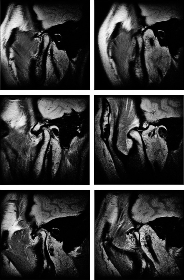
Temporomandibular joint (TMJ) magnetic resonance imaging (MRI) images: left, closed mouth; right, open mouth. Top, normal status; middle, anterior disk displacement with reduction; bottom, anterior disk displacement without reduction.
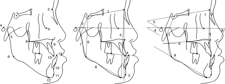
Posteroanterior (PA) and lateral cephalograms of each patient (taken with teeth in habitual maximum intercuspation and lips in repose with a magnification ratio of 1∶1) were traced by one of the authors. The tracings were then digitized and analyzed. For the lateral cephalometric radiograph, 11 linear, seven angular, and three proportional measurements were analyzed for the lateral cephalometric evaluation of the cranial base, maxilla, mandible, antero-posterior relationships, and vertical relationships (Figure 2).
Figure 2.
Lateral cephalometric analysis. Left, lateral cephalometric landmarks: 1, sella; 2, nasion; 3, orbitale; 4, porion; 5, articulare; 6, gonion; 7, anterior nasal spine; 8, posterior nasal spine; 9, subspinale; 10, supramentale; 11, pogonion; 12, menton: 13, crown tip of upper central incisor; 14, crown tip of lower central incisor. Middle, linear measurement of lateral cephalometry: 1, S-N; 2, S-Ar; 3, Pog to N perpendicular; 4, Wits appraisal; 5, anterior facial height (N-Me); 6, posterior facial height angle (S-Go); 7, ramus height (Ar-Go); 8, mandibular body length (Go-Me). Right, angular measurements: 1, SNA angle; 2, SNB angle; 3, ANB; 4, FMA; 6, SN to mandibular plane angle; 7, FH to palatal plane angle; 7, articular angle; 8, mandibular incisor to FH plane; 9, gonial angle.
To evaluate the facial asymmetry, the landmarks on the PA cephalogram were identified with the methods recommended by Sassouni22 and Ricketts et al.23 (Figure 3). According to methods outlined in previous studies,22,24,25 the facial midline was defined as a line perpendicular to the line connecting Lo and Lo′ through Nc. When the landmark was located left of the midline, a positive value was assigned.
Figure 3.
Posteroanterior (PA) cephalometric analysis. Left, PA cephalometric landmarks: Lo, bilateral intersection of the oblique orbital line with the lateral contour of the right and left side orbits; Nc, neck of crista galli; ANS, anterior nasal spine; Me, menton; J, jugal process of the maxilla at a crossing with the tuberosity of the maxilla; Ag, the highest point in the antegonial notch; U1, mesial contact point of upper central incisors at the level of gingival crest; L1, mesial contact points of lower incisors at the level of gingival crest; U6, the buccal-most point on the crown of the upper first molar; L6, the buccal-most point on the crown of the lower first molar. Middle, PA linear measurements: ANS-Mid, horizontal distance from vertical reference line to ANS; U1-Mid, horizontal distance from vertical reference line to U1; L1-Mid, horizontal distance from vertical reference line to L; Men-Mid, horizontal distance from vertical reference line to menton. Right, PA angular measurements: FMxP, frontal maxillary plane angle; FOP, frontal occlusal plane angle; FMdP, frontal mandibular plane angle.
One-way analysis of variance and Scheffè multiple comparisons was utilized to compare the four groups. Relative risk ratio was calculated to measure how much facial asymmetry influenced the risk of asymmetric DD.
RESULTS
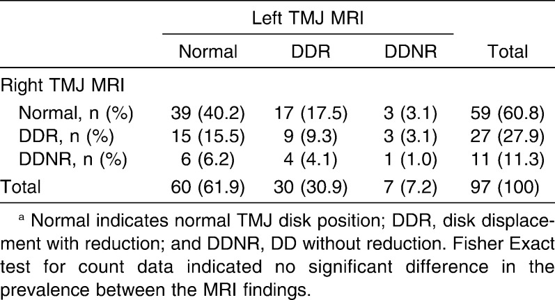
The distribution of subjects according to TMJ MRI reading, gender, and mean age of each group is summarized in Table 1. Sixty percent of subjects had DDR or DDNR in at least one of their TMJs, and 40% of subjects showed normal disk status (Table 2). Out of 194 total TMJs, 75 TMJs (38.7%) had DDR or DDNR. Among the 97 patients, 63 patients had TMJ symptoms, which showed no statistically significant difference between the MRI findings. The most frequent symptom for each TMJ was “TMJ sounds only” (40–50%), followed by “both pain and sounds” (24–30%) (Table 3).
Table 1.
Distribution of Subjectsa
Table 2.
Cross-Table of Temporomandibular Joint (TMJ) Magnetic Resonance Imaging (MRI) Resultsa
Table 3.
Distribution of Temporomandibular Joint (TMJ) Symptoms and Magnetic Resonance Imaging (MRI) Findingsa
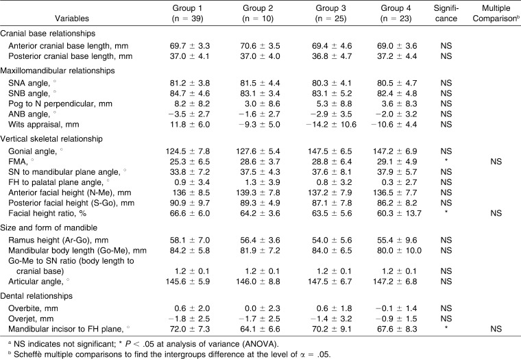
Although there were few differences in the lateral cephalometric variables, including FMA, facial height ratio, and mandibular incisor to FH plane, the Scheffè's multiple comparisons did not indicate statistical significance (Table 4).
Table 4.
Comparison of Lateral Cephalometric Variablesa
Table 5 reports the comparisons of the PA cephalometric variables among the four groups. The linear measurements evaluating the amount of maxillary asymmetry (ANS-Mid and U1-Mid) were not significant. However, the linear variables evaluating the amount of mandibular asymmetry (L1-Mid and Men-Mid) did show significant differences. Since a positive sign indicates that the landmark was located left of the midline, the results demonstrate that there was a right-sided mandibular shift in group 3 and a left-sided mandibular shift in group 4.
Table 5.
Comparison of Posteroanterior (PA) Cephalometric Variables of Subjectsa
To eliminate the effect of positive and negative signs and to concentrate on the quantitative comparison, the absolute values of each variable were taken and compared. Comparisons of the absolute value of linear measurements also demonstrated statistical significance at L1-Mid and Men-Mid. This indicates that the absolute amount of mandibular asymmetry was greater in groups 3 and 4 than in groups 1 and 2. The angular measurement that evaluates vertical asymmetry demonstrated that all of the variables (FMxP, FOP, and FMdP) resulted in statistical differences. However, in the comparisons of the absolute value of angular measurements, only FMdP was statistically significant.
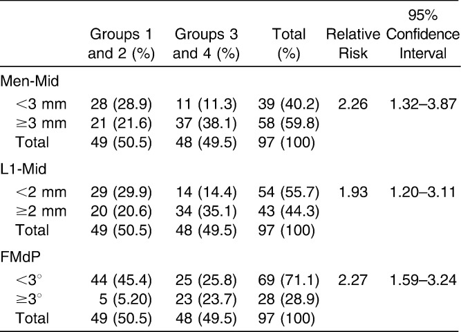
The relative risks for the amount of mandibular deviation were calculated by comparing groups 3 and 4 to groups 1 and 2 (Table 6). The relative risk of groups 3 and 4 over groups 1 and 2 for the deviation of menton more than 3 mm was 2.26. For the deviation of the midline of the lower incisors more than 2 mm, the relative risk was 1.93. For a FMdP angle of greater than 3°, the relative risk was 2.27.
Table 6.
Relative Risk Ratios
DISCUSSION
There have been a number of studies that have attempted to correlate temporomandibular disease (TMD) and skeletal morphology, especially with regard to facial asymmetry. Most previous studies included patients with TMD symptoms or facial asymmetry but did not focus on specific skeletal features. Our study randomized skeletal Class III patients with and without TMD symptoms or asymmetry and analyzed features of lateral and PA cephalograms in combination with MRI readings.
There are a number of causes for facial asymmetry as well as for TMJ DD. Thus, it is difficult to describe the clear cause and effect between them. However, to date the data indicate that facial asymmetry, especially mandibular asymmetry, can influence the shape and function of the TMJ and vice versa. In other words, TMJ DD can be the cause of facial asymmetry.13,14,26,27 If DD becomes progressive, it might cause bony changes.28 An irregularly shaped right or left joint can also easily cause a problem.29 This was proven in a previous study18 using finite element analysis. Therefore, facial asymmetry associated with TMJ DD may be due to osseous changes in the condylar head by TMJ DD. Previous studies30,31 have reported bony changes on the articular surface of the mandibular condyle in patients with TMJ DD, specifically a decreased condylar height with a distally inclined condylar head. The changes in the shape and size of the mandibular condyle may induce mandibular shortening of the DD side, namely mandibular asymmetry and facial asymmetry.
In this study, the manifest site and degree of TMJ DD correlated more with facial asymmetry in the mandible than in the maxilla. The variables evaluating the maxillary asymmetry did not demonstrate a significant difference between the groups. This may indicate that the basic cause for asymmetry in skeletal Class III malocclusions lies in the mandible (Table 5). Class III often reoccurs after Class III surgery. The reoccurrence might be related to the fact that Class III malocclusion may sometimes represent progressive condylar hyperplasias, some bilateral and some unilateral or DD on one side, possibly affecting growth, and sometimes bilateral.
In the mandible, the deviation of mandibular menton and the frontal mandibular plane angle showed clear differences between the groups. In the group showing normal or identical conditions of DD in both TMJs (groups 1 and 2), the asymmetry of the mandible was not significant. However, when one of the TMJs with DD, either right or left, was more advanced on one side than on the other side, the mandible was shifted toward the side with greater DD. This indicates that TMJ DD showed laterality, and its direction was in accordance with the side with the shifted midline. The mandible has a positive or negative sign indicating the direction of the deviation. Calculating the average midline displacement can offset this sign. Therefore, if the direction of the deviation (± sign from Table 5) is not considered when calculating the real displacement, a significant difference in the horizontal deviation of the midline of the lower incisors, menton, and the frontal mandibular plane angle is also observed. This calculation demonstrated that the side with the more advanced TMJ DD was also the shifted side of the mandible.
In a previous study32 of skeletal Class I and II malocclusion patients, the research on lateral cephalograms demonstrated significant differences in terms of facial height ratio, ramus height, and position of the mandible between a normal group and a group having bilateral DD. However, our study did not show a significant difference. It is possible that the relation between TMJ DD and skeletal morphology is influenced in different ways by differences in skeletal pattern. For example, in the skeletal Class II malocclusion, TMJ DD mainly influences the TMJ bilaterally, resulting in mandibular clockwise rotation, an anterior open bite, and a large overjet.32 On the other hand, in the cases of patients with skeletal Class III malocclusion and facial asymmetry, the TMJ on the shifted side of the mandible entailed an extreme prevalence of DD.
According to the degree of mandibular asymmetry and the relative risk of groups 3 and 4 over groups 1 and 2 (Table 6), patients who demonstrated more than 3 mm or 3° of asymmetry had a greater probability of having different levels of TMJ DD on each side. On the contrary, patients with relatively little asymmetry fell into the normal TMJ group or the bilateral TMJ DD group. Therefore, the results of this study indicate that if either the left or right TMJ has greater DD than the opposite side, the mandibular displacement will be seen on the more advanced side. If both TMJs are normal or have the same amount of DD, the facial asymmetry is not outstanding.
It is necessary to discriminate the latent TMJ DD patients during the orthodontic diagnosis and to make them aware of their preexisting condition before initiating treatment. In reality, TMJ DD may be less related to unwanted signs and symptoms than has been previously postulated.17,27,33 According to the results of this study's skeletal Class III mandibular asymmetrical patients, we can infer that both the frontal mandibular plane angle (which indicates the horizontal asymmetry of the mandible) and the horizontal deviation of the lower incisor (measured from the vertical reference line) indicate the possibility of advanced TMJ DD on the side of mandibular displacement. Another possibility is that both joints may have DD to the same degree when the mandibular asymmetry is not prominent.
CONCLUSIONS
When the TMJ DD is more advanced on one side, the mandible usually deviates to the advanced side.
When the TMJ DD is bilaterally equal or bilaterally normal, the amount of mandibular deviation is not significant. Therefore, if a skeletal Class III patient has an asymmetric face, especially in the mandibular region, careful examination might be necessary regarding the status of the TMJ during orthodontic diagnosis and treatment planning.
Acknowledgments
This research was partly supported by grant 03-2010-0023 from the SNUDH Research Fund.
REFERENCES
- 1.Eversole L. R, Machado L. Temporomandibular joint internal derangements and associated neuromuscular disorders. J Am Dent Assoc. 1985;110:69–79. doi: 10.14219/jada.archive.1985.0283. [DOI] [PubMed] [Google Scholar]
- 2.Schellhas K. P, Piper M. A, Omlie M. R. Facial skeleton remodeling due to temporomandibular joint degeneration: an imaging study of 100 patients. Cranio. 1992;10:248–259. doi: 10.1080/08869634.1992.11677918. [DOI] [PubMed] [Google Scholar]
- 3.Gidarakou I. K, Tallents R. H, Kyrkanides S, Stein S, Moss M. Comparison of skeletal and dental morphology in asymptomatic volunteers and symptomatic patients with bilateral degenerative joint disease. Angle Orthod. 2003;73:71–78. doi: 10.1043/0003-3219(2003)073<0071:COSADM>2.0.CO;2. [DOI] [PubMed] [Google Scholar]
- 4.Schellhas K. P, Piper M. A, Bessette R. W, Wilkes C. H. Mandibular retrusion, temporomandibular joint derangement, and orthognathic surgery planning. Plast Reconstr Surg. 1992;90:218–229, 230–212. [PubMed] [Google Scholar]
- 5.Westesson P. L. Structural hard-tissue changes in temporomandibular joints with internal derangement. Oral Surg Oral Med Oral Pathol. 1985;59:220–224. doi: 10.1016/0030-4220(85)90022-2. [DOI] [PubMed] [Google Scholar]
- 6.Westesson P. L. Reliability and validity of imaging diagnosis of temporomandibular joint disorder. Adv Dent Res. 1993;7:137–151. doi: 10.1177/08959374930070020401. [DOI] [PubMed] [Google Scholar]
- 7.Tasaki M. M, Westesson P. L. Temporomandibular joint: diagnostic accuracy with sagittal and coronal MR imaging. Radiology. 1993;186:723–729. doi: 10.1148/radiology.186.3.8430181. [DOI] [PubMed] [Google Scholar]
- 8.Baccetti T, Antonini A, Franchi L, Tonti M, Tollaro I. Glenoid fossa position in different facial types: a cephalometric study. Br J Orthod. 1997;24:55–59. doi: 10.1093/ortho/24.1.55. [DOI] [PubMed] [Google Scholar]
- 9.Nebbe B, Major P. W, Prasad N. Female adolescent facial pattern associated with TMJ disk displacement and reduction in disk length: part I. Am J Orthod Dentofacial Orthop. 1999;116:168–176. doi: 10.1016/s0889-5406(99)70214-3. [DOI] [PubMed] [Google Scholar]
- 10.Nebbe B, Major P. W, Prasad N. G. Adolescent female craniofacial morphology associated with advanced bilateral TMJ disc displacement. Eur J Orthod. 1998;20:701–712. doi: 10.1093/ejo/20.6.701. [DOI] [PubMed] [Google Scholar]
- 11.Trpkova B, Major P, Nebbe B, Prasad N. Craniofacial asymmetry and temporomandibular joint internal derangement in female adolescents: a posteroanterior cephalometric study. Angle Orthod. 2000;70:81–88. doi: 10.1043/0003-3219(2000)070<0081:CAATJI>2.0.CO;2. [DOI] [PubMed] [Google Scholar]
- 12.Inui M, Fushima K, Sato S. Facial asymmetry in temporomandibular joint disorders. J Oral Rehabil. 1999;26:402–406. doi: 10.1046/j.1365-2842.1999.00387.x. [DOI] [PubMed] [Google Scholar]
- 13.Schellhas K. P, Pollei S. R, Wilkes C. H. Pediatric internal derangements of the temporomandibular joint: effect on facial development. Am J Orthod Dentofacial Orthop. 1993;104:51–59. doi: 10.1016/0889-5406(93)70027-L. [DOI] [PubMed] [Google Scholar]
- 14.Dibbets J. M, van der Weele L. T, Uildriks A. K. Symptoms of TMJ dysfunction: indicators of growth patterns? J Pedod. 1985;9:265–284. [PubMed] [Google Scholar]
- 15.Brand J. W, Nielson K. J, Tallents R. H, Nanda R. S, Currier G. F, Owen W. L. Lateral cephalometric analysis of skeletal patterns in patients with and without internal derangement of the temporomandibular joint. Am J Orthod Dentofacial Orthop. 1995;107:121–128. doi: 10.1016/s0889-5406(95)70126-5. [DOI] [PubMed] [Google Scholar]
- 16.Bosio J. A, Burch J. G, Tallents R. H, Wade D. B, Beck F. M. Lateral cephalometric analysis of asymptomatic volunteers and symptomatic patients with and without bilateral temporomandibular joint disk displacement. Am J Orthod Dentofacial Orthop. 1998;114:248–255. doi: 10.1016/s0889-5406(98)70206-9. [DOI] [PubMed] [Google Scholar]
- 17.Gidarakou I. K, Tallents R. H, Kyrkanides S, Stein S, Moss M. E. Comparison of skeletal and dental morphology in asymptomatic volunteers and symptomatic patients with bilateral disk displacement without reduction. Angle Orthod. 2004;74:684–690. doi: 10.1043/0003-3219(2004)074<0684:COSADM>2.0.CO;2. [DOI] [PubMed] [Google Scholar]
- 18.Buranastidporn B, Hisano M, Soma K. Articular disc displacement in mandibular asymmetry patients. J Med Dent Sci. 2004;51:75–81. [PubMed] [Google Scholar]
- 19.Byun E. S, Ahn S. J, Kim T. W. Relationship between internal derangement of the temporomandibular joint and dentofacial morphology in women with anterior open bite. Am J Orthod Dentofacial Orthop. 2005;128:87–95. doi: 10.1016/j.ajodo.2004.01.028. [DOI] [PubMed] [Google Scholar]
- 20.Severt T. R, Proffit W. R. The prevalence of facial asymmetry in the dentofacial deformities population at the University of North Carolina. Int J Adult Orthod Orthognath Surg. 1997;12:171–176. [PubMed] [Google Scholar]
- 21.Ahn S. J, Lee S. P, Nahm D. S. Relationship between temporomandibular joint internal derangement and facial asymmetry in women. Am J Orthod Dentofacial Orthop. 2005;128:583–591. doi: 10.1016/j.ajodo.2004.06.038. [DOI] [PubMed] [Google Scholar]
- 22.Sassouni V. Position of the maxillary first permanent molar in the cephalofacial complex: a study in three dimensions. Am J Orthod. 1957;43:477–510. [Google Scholar]
- 23.Ricketts R, Bench R, Gugino C, Hilgers J, Schullof R. Bioprogressive Therapy. Denver, Colo: Rocky Mountain Orthodontics; 1979. [Google Scholar]
- 24.Park S. B, Park J. H, Jung Y. H, Jo B. H, Kim Y. I. Correlation between menton deviation and dental compensation in facial asymmetry using cone-beam CT. Korean J Orthod. 2009;39:300–309. [Google Scholar]
- 25.Sun M. K, Uhm G. S, Cho J. H, Hwang H. S. Use of Head Posture Aligner to improve accuracy of frontal cephalograms generated from cone-beam CT scans. Korean J Orthod. 2009;39:289–299. [Google Scholar]
- 26.Kambylafkas P, Kyrkanides S, Tallents R. H. Mandibular asymmetry in adult patients with unilateral degenerative joint disease. Angle Orthod. 2005;75:305–310. doi: 10.1043/0003-3219(2005)75[305:MAIAPW]2.0.CO;2. [DOI] [PubMed] [Google Scholar]
- 27.Hans M. G, Lieberman J, Goldberg J, Rozencweig G, Bellon E. A comparison of clinical examination, history, and magnetic resonance imaging for identifying orthodontic patients with temporomandibular joint disorders. Am J Orthod Dentofacial Orthop. 1992;101:54–59. doi: 10.1016/0889-5406(92)70082-L. [DOI] [PubMed] [Google Scholar]
- 28.Larheim T. A. Current trends in temporomandibular joint imaging. Oral Surg Oral Med Oral Pathol Oral Radiol Endod. 1995;80:555–576. doi: 10.1016/s1079-2104(05)80154-4. [DOI] [PubMed] [Google Scholar]
- 29.Pirttiniemi P, Kantomaa T, Lahtela P. Relationship between craniofacial and condyle path asymmetry in unilateral cross-bite patients. Eur J Orthod. 1990;12:408–413. doi: 10.1093/ejo/12.4.408. [DOI] [PubMed] [Google Scholar]
- 30.Ahn S. J, Kim T. W, Lee D. Y, Nahm D. S. Evaluation of internal derangement of the temporomandibular joint by panoramic radiographs compared with magnetic resonance imaging. Am J Orthod Dentofacial Orthop. 2006;129:479–485. doi: 10.1016/j.ajodo.2005.12.009. [DOI] [PubMed] [Google Scholar]
- 31.Kurita H, Ohtsuka A, Kobayashi H, Kurashina K. Relationship between increased horizontal condylar angle and resorption of the posterosuperior region of the lateral pole of the mandibular condyle in temporomandibular joint internal derangement. Dentomaxillofac Radiol. 2003;32:26–29. doi: 10.1259/dmfr/23245517. [DOI] [PubMed] [Google Scholar]
- 32.Ahn S. J, Kim T. W, Nahm D. S. Cephalometric keys to internal derangement of temporomandibular joint in women with Class II malocclusions. Am J Orthod Dentofacial Orthop. 2004;126:486–494. doi: 10.1016/j.ajodo.2003.08.029. [DOI] [PubMed] [Google Scholar]
- 33.Paesani D, Westesson P. L, Hatala M, Tallents R. H, Kurita K. Prevalence of temporomandibular joint internal derangement in patients with craniomandibular disorders. Am J Orthod Dentofacial Orthop. 1992;101:41–47. doi: 10.1016/0889-5406(92)70080-T. [DOI] [PubMed] [Google Scholar]


