Abstract
3D bio-printing is an emerging technology to fabricate tissue scaffold in-vitro through the controlled allocation of biomaterial and cells, which can mimic the in-vivo counterpart of living tissue. Live cells are often encapsulated into the biomaterials (i.e., bio-ink) and extruded by controlling the printing parameters. The functionality of the bioink depends upon three factors: (a) printability, (b) shape fidelity, and (c) bio-compatibility. Increasing viscosity will improve the printability and the shape fidelity but require higher applied extrusion pressure, which is detrimental to the living cell dwelling in the bio-ink, which is often ignored in the bio-ink optimization process. This paper demonstrates a roadmap to develop and optimize bio-inks, ensuring printability, shape fidelity, and cell survivability. The pressure exerted on the bio-ink during extrusion processes is measured analytically, and the information is incorporated in the bio-ink’s rheology design. Cell-laden filaments are fabricated with multiple cell lines, i.e., Human Embryonic Kidney (HEK 293), BxPC3, and prostate cancer cells which are analyzed for cell viability. The cross-sectional live-dead assay of the extruded filament demonstrates a spatial pattern for HEK 293 cell viability, which correlates with our analytical finding of the shear stress at the nozzle tip. All three cell lines were able to sustain a transient shear stress of 3.7 kPa and demonstrate 90% viability with our designed bio-ink after 15 days of incubation. Simultaneously, the shape fidelity and printability matrices show its suitability for 3D bio-printing process.
Keywords: bioink, rheology, shear thinning, extrusion bioprinting
1. Introduction
Three-dimensional (3D) bio-printing has gained significant attention to fabricate cell encapsulated 3D biomimetic scaffolds for tissue regeneration in recent times. Scaffolds are fabricated using a computer-controlled 3D printer with bio-ink prepared by encapsulating [1–4] live cells into biomaterials or synthetic bio-polymers or metals by seeding [5, 6] cells. Various types of 3D bio-printing techniques have been developed, including laser-assisted [7, 8], inkjet [9], and extrusion-based bio-printing [10, 11]. Among them, extrusion-based bio-printing gets more attention due to its ability to use a diverse range of materials and compositions [10, 11].
The functionality of the bioink depends upon three factors: (a) printability, (b) shape fidelity, and (c) bio-compatibility [12]. Printability in extrusion 3D printing is often indicated as 1) extrudability of bio-inks during extrusion characterized by rheological properties and 2) formability of filaments after extrusion featured by shape fidelity of the filaments and structures. Immediate deformation after the release of the pure hydrogel can be restricted by developing enough yield strength through quick gelation, which will affect the overall geometry of the fabricated scaffold [13] as shown in Figure 1. The rate of gelation can be controlled by controlling the rheological properties of hydrogels by adding a viscosity modifier [14–16], changing temperature [17–19], and an external cross-linker [20, 21]. A plethora of recent literature is focused on optimizing the bio-ink for their printability and shape fidelity [22, 23]. However, optimizing them not necessarily always increase the bio-compatibility aspect of the bio-ink. For example, increasing viscosity will improve printability and shape fidelity. Still, it will require higher applied extrusion pressure, which is detrimental to the living cell dwelling in the bio-ink.
Figure. 1.
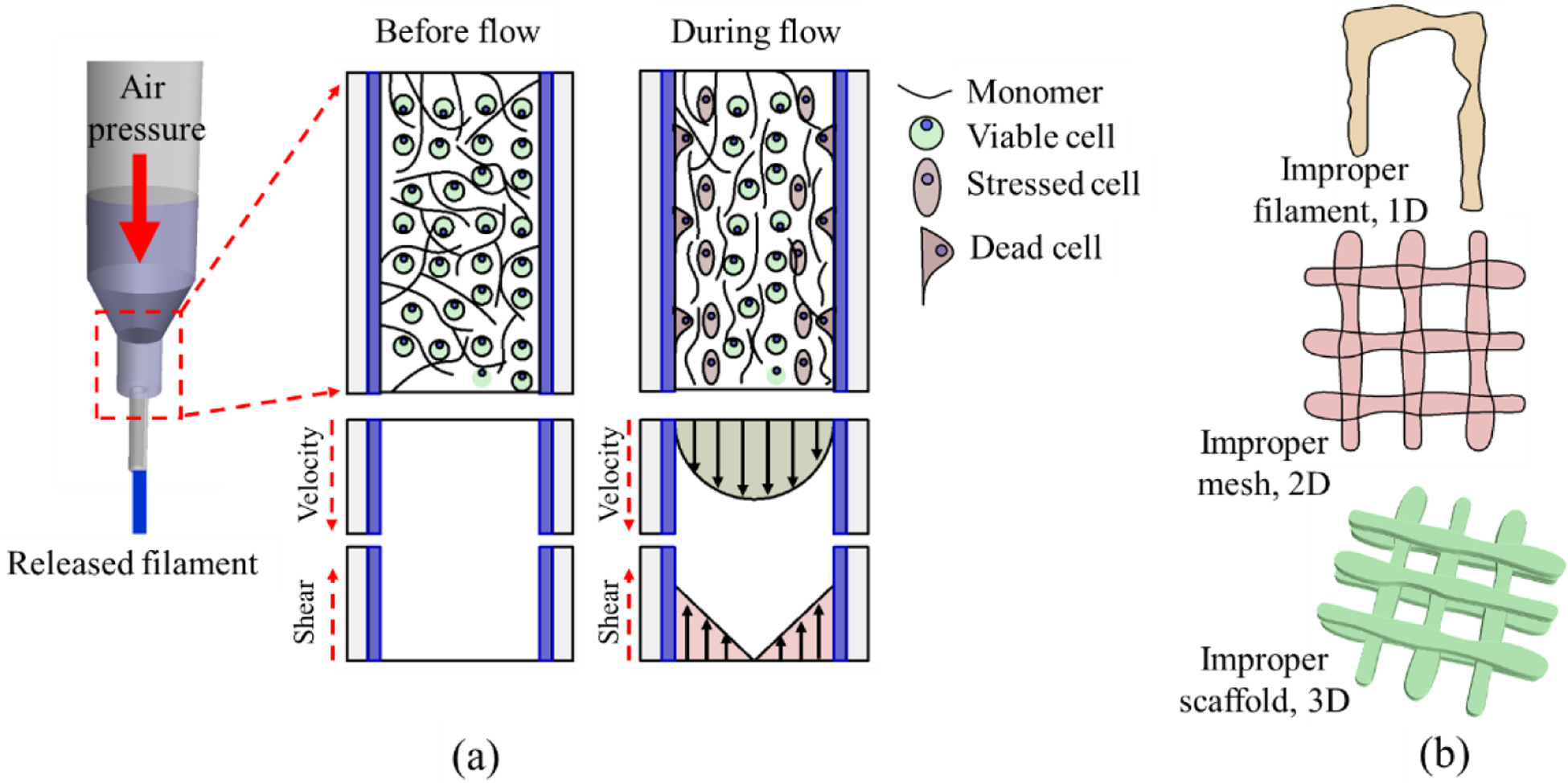
(a) Cell damage due to high shear stress (b) Improper filament, mesh, and scaffold geometry due to low viscous hydrogel.
The extrusion-based printing process uses the air pressure to dispense the cell-laden filament through a nozzle orifice by pneumatic and mechanical assistance [24, 25]. Often time, the impact of mechanical stress on cells is immeasurable. Although some study suggests, a controlled applied load on the living cells can facilitate their growth, locomotion, and differentiation [26], process-induced stress can damage the cell membrane integrity, causing a quantifiable loss in cell viability [22]. Especially, the mammalian cells are highly sensitive to mechanical forces due to only having plasma membrane and are prone to cell lysis under shear stress [27]. Moreover, the alteration of mechanical signals caused by cell geometry changes can change chemical signals that may undermine cellular development [28]. Since the extrusion-based technique uses a syringe-based deposition system, alteration of this dispensing nozzle/needle diameter will mechanically affect the cell viability, as shown in Figure 1(a). Specifically, reducing nozzle diameter and increasing the applied pressure will increase the shear force on the cell during deposition and reduce the cell viability. The effect of shear stress becomes prominent close to the nozzle surface during material extrusion that eventually may affect the cell viability and proper cell phenotype [29, 30]. Moreover, the cell inside the solution may experience additional compressive or tensile forces due to the nozzle head movement concerning the substrate [31]. Therefore, analytical investigation of the shear stress into the nozzle during bio-ink extrusion can provide useful information on cell survivability [32].
The focus of this paper is to demonstrate a bio-inks development roadmap to ensure printability, shape fidelity, and cell survivability. The overall cell viability in the scaffolds fabricated by extrusion-based 3D bio-printing technique depends on the shear stress experienced by encapsulated cells. We investigate the resultant shear stress exerted on encapsulated cells considering material viscosity, applied pressure, and nozzle diameter, which is then correlated with bio-ink functionality (i.e., printability, shape fidelity, and cell viability). To demonstrate, we used a hybrid hydrogel composition reported in our earlier work [33], which is made of Alginate (alginic acid sodium salt from brown algae) and medium viscosity carboxymethyl cellulose (CMC). The pressure exerted on the bio-ink during extrusion processes is measured analytically, and the information is incorporated in the bio-ink’s rheology design. Cell-laden filaments are fabricated with multiple cell lines, i.e., Human Embryonic Kidney (HEK 293), BxPC3, and prostate cancer cells which are analyzed for cell viability. The cross-sectional live-dead assay of the extruded filament demonstrates a spatial pattern for HEK 293 cell viability which correlates with our analytical finding of the shear stress at the nozzle tip. Following our investigation, we are able to achieve more than 90% cell viability for all three cell lines after 15 days of incubation.
2. Material and method
Bio-compatibility and capacity to arrange a 3D environment with a high water content make hydrogel a suitable candidate material for the extrusion-based bioprinting process [34]. The flowability or the rheological properties of the low viscous hydrogel is amenable for extrusion but may not help to maintain proper filament shape fidelity. Moreover, due to the lack of bio-ligands necessary for mammalian cell attachment, alginate has limited effectiveness as a bio-ink [35]. We added carboxymethyl cellulose (CMC) as the viscosity modifier in designing the bio-ink in our investigation. While high viscous hydrogel can ensure the post-printing shape fidelity, the applied pressure to extrude that hydrogel can adversely affect the encapsulated cell due to high shear stress [29, 30]. Thus balancing the troika (i.e., printability, shape fidelity, and bio-compatibility) is a non-trivial task. Additionally, the property of the bio-ink alone is not sufficient for a successful 3D bio-printing process. As the material is extruded through the small orifice, the effective shear stress can increase dramatically due to the change in printing parameters (i.e., nozzle diameter, applied pressure), which are often ignored in bio-ink optimization processes.
2.1. Hybrid hydrogel preparation
Alginate (alginic acid sodium salt from brown algae) and medium viscosity carboxymethyl cellulose (CMC) (Sigma-Aldrich, St. Louis, MO, USA)) are used as biomaterials to prepare the bio-ink. Alginate is a common bio-copolymer (β-Dmannuronic, M and Lguluronic acids, G blocks) negatively charged, soluble in the water and supports cell encapsulation. The G-block of this material supports to form gels where GM and M blocks increase the flexibility. Carboxymethylcellulose (CMC) is another anionic water-soluble bio-copolymer of β-D-glucose and β-D-glucopyranose-2-O-(carboxymethyl)-mono-sodium salt connected via β-1,4-glucosidic bonds [36]. This material is widely used as a thickener [37], which is also non-toxic and non-allergenic. The presence of carboxyl groups makes this cellulose derivative more soluble, thicken, and stable [36].
The detailed preparation of bio-ink is explained elsewhere [33], and a short overview of preparing the bio-ink is shown in Figure 2. A fixed 4% (w/v) of alginate is dissolved with various percentages of CMC i.e. 0%, 1%, 2%, 3%, 4% (w/v) into PBS and stirred overnight to get uniform mixture of alginate and CMC. Preparing hybrid hydrogels using upto 4% (w/v) alginate can create an amenable micro-environment for encapsulated cells and help maintain high cell viability [38, 39]. This also defines the proper shape fidelity of the fabricated scaffolds due to the quick cross-linking with CaCl2. Using a higher percentage of alginate or other components in the hybrid hydrogel may require an elevated amount of applied pressure to extrude through the nozzle that can negatively impact the encapsulated cell, and eventually reduce the cell viability [40, 41]. Therefore, the solid content was kept at or below 8% for balancing the troika discussed above. The mixture is autoclaved at 1210C for 20 min to get sterile bio-inks. Alginate and CMC are expressed with ‘A’ and ‘C’, respectively. The subscripts of ‘A’ and ‘C’ in Figure 2 are indicating the weight percentages.
Figure. 2.
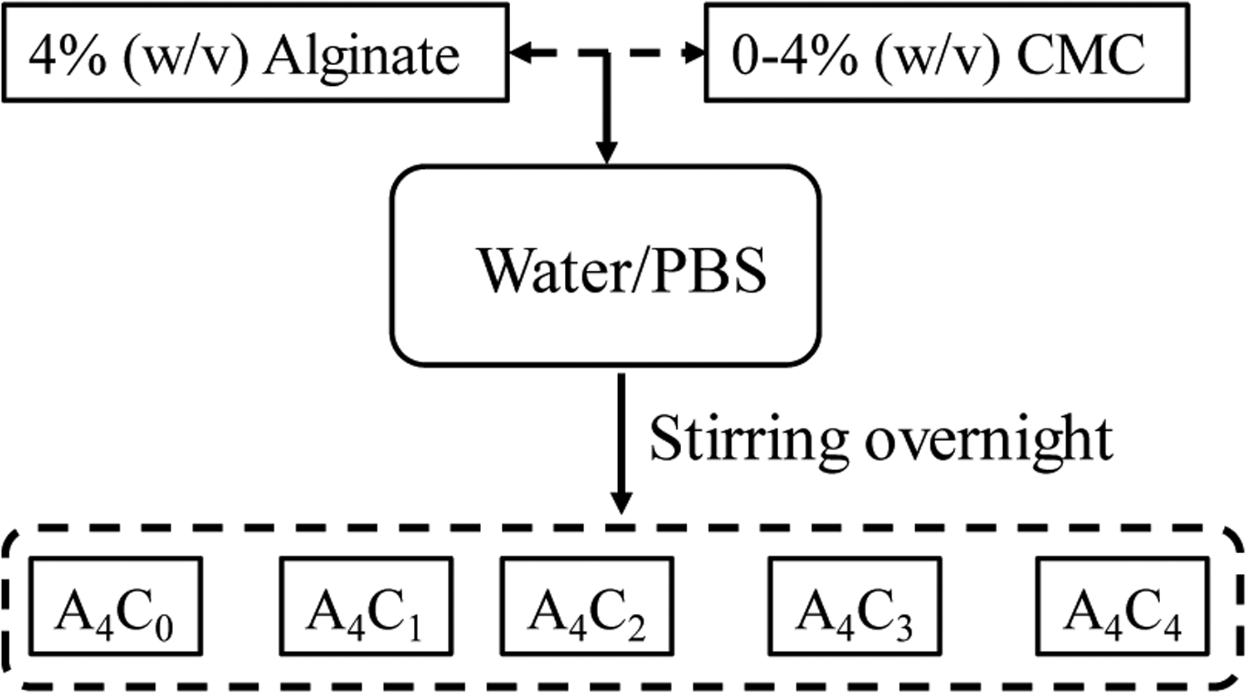
Preparing hybrid hydrogel by mixing 4% (w/v) alginate and 0–4% (w/v) CMC.
2.2. Rheological measurement
Rheological measurements are performed using a rotational rheometer (ARES-LS2, TA instruments, New Castle, DE, USA) with parallel plate geometry (20 mm flat plate). All measurements are recorded with a 1.0 mm gap width at 25°C. The viscosities and shear stress of different compositions were assessed with flow curves at a range of 1.0 to 100 s−1 shear strain rate. The dynamic sweep stress test is performed at a shear strain range of 1.0 to 100% to determine the solid and liquid-like state of different bio-inks. Three intervals thixotropic test (3iTT) was performed at a shear strain rate of 1.0 to 100% to determine all compositions’ recovery rate. By plotting the rheological measures, the composition’s flow characteristic parameters can be determined from the Power-Law Equation (Equation 1) [42].
| (1) |
Where, η is the viscosity, is the shear rate, and K and n are the shear-thinning coefficients. The linear region of the shear rate vs. viscosity plot can be used to interpolate the power n, while the intersection of the curve at zero-shear rate defines the parameter K. The value of n determines the shape of the curve and, more importantly, define the shear-thinning behavior of the candidate material. For example, if the value is less than 1, then the material demonstrates shear thinning behavior required for the extrusion process. While the material is extruded through the nozzle, the material experiences shear stress across the nozzle’s cross-sectional area. A viscous sub-layer forms around the wall, which is dead and considered as zero-motion. In contrast, the material along the center moves fast at a maximum speed. The shear rate experienced by the bio-ink at the nozzle wall during the printing can be estimated using Equation 2 [43, 44].
| (2) |
Where is the average extrusion velocity which is often considered as the print speed or nozzle moving speed. In an ideal extrusion process, the printing speed and the volume of flowing material through the dispensing nozzle should be synchronized, and hence the filament thickness can be controlled accurately [44]. This assumption supports the equality between extrusion velocity and nozzle speed. However, it has been experimentally found that the filament diameter and the material volume eventually can vary even if the pressure and the parameters influencing the extrusion materials are kept constant [45]. Once the shear rate is estimated using the estimated velocity, the corresponding shear stress can be determined using Equation 3.
| (3) |
Where τ is the shear stress measured on the bio-ink. These analytical expressions are derived under certain assumptions, and the actual result may vary with the material properties. Localized variation in viscosity, wall slippage, or low friction may often be attributed to the differences in actual vs. analytical shear stresses, which is very difficult to measure. In this paper, we analyzed the printed filament using 410-micron nozzle size, 8 psi pressure and found extrusion velocity is larger than the print head speed, which will produce the filament width larger than the needle diameter. The ratio of this enlargement is defined as the velocity correction factor, which is used to determine the in Equation 2 and shown in Table 1. As the material is pushed through the nozzle, the gel material will deform due to the applied shear and start flowing. The spatial distribution of the extrusion velocity profile across the nozzle cross-section can be estimated using the following equation:
| (4) |
Table. 1.
Shear-thinning co-efficient and shear rate during extrusion and corresponding viscosity for 8 psi extrusion pressure and 410 μm nozzle diameter.
| Compositions | Filament width (μm) | Increase factor | Average velocity (mm/s) | n | K | Shear rate (s−1) | Viscosity (Pa.S) | Shear stress (Pa) |
|---|---|---|---|---|---|---|---|---|
| A4C4 | 675.33 | 1.65 | 6.59 | 0.38 | 522.47 | 181.94 | 20.30 | 3692.83 |
| A4C3 | 782.33 | 1.91 | 7.63 | 0.49 | 280.08 | 198.63 | 13.60 | 2700.93 |
| A4C2 | 883.67 | 2.16 | 8.62 | 0.38 | 229.41 | 237.65 | 7.60 | 1806.61 |
| A4C1 | 1086 | 2.65 | 10.59 | 0.65 | 20.95 | 234.53 | 3.11 | 728.64 |
| A4C0 | 1280.67 | 3.12 | 12.49 | 0.70 | 0.67 | 269.76 | 0.13 | 34.19 |
Where Δp is the applied pressure, L is the nozzle length, and r is the distance of any location from the nozzle center. The corresponding shear rate can be predicted using the estimated extrusion velocity using Equation 2. The distribution of viscosity and shear stress can be estimated using the predicted shear rate using Equations 1 and 3, respectively.
2.3. Preparation of cell-laden bio-ink and scaffold fabrication
Three cell lines (i) pancreatic cancer cell BxPC3; (ii) prostate cancer stem cell; and (iii)human embryonic kidney (HEK 293) cells were mixed with 4% Alg-4% CMC composition to evaluate the cell survivability. BxPC3 and HEK cells were cultured and maintained in high glucose DMEM, 2 mM Glutamine, and 10% Fetal Bovine Serum (FBS) with 100 μg /ml penicillin and 100 μg/ml streptomycin (Sigma-Aldrich) in 5% CO2 at 37°C incubator. For Porc1 cells, DMEM/F12 were used instead of DMED maintaining other conditions unchanged. The culture medium is changed twice a week. Cells at passage 5 are used for 3D bio-printing.
An amount of 12×106 2D cultured cells were trypsinized, centrifuged, re-suspended into a 200μl of culture medium, and mixed into the 1.0 ml sterile hydrogel solution. The cell was mixed uniformly with a magnetic stirrer to get the final cell concentration of 10×106 cell/ml in our cell-laden bio-ink. Once mixed, the bio-inks were placed in a disposable barrel reservoir (EFD, Nordson) to fabricate the scaffolds and dispensed through a dosing nozzle (EFD, Nordson, the inner diameter 410 μm) with pneumatic pressure. The time between adding cells to print was kept within 20 minutes to ensure adherent cells are still remain suspended in the bio-ink. After fabrication, the scaffold was cross-linked with CaCl2, washed three times with HBSS, and finally incubated into the same type of fresh media used for 2D culture with 37°C temperature, 5% CO2, and more than 90% humidity.
An in-house developed XYZ-axis 3D bio-printer is used to fabricate the cell-free and cell-laden scaffolds under sterile conditions. The visual-basic based scripting language is used to generate the vectorized toolpath of the scaffold and converted into the machine-readable language. The bio-ink was stored in a disposable barrel reservoir (EFD, Nordson, Westlake, OH, USA) and dispensed applying air pressure through a dosing nozzle (EFD, Nordson, the inner diameter 410 μm) on a stationary print bed. A 0°/90° grid fashion was used to fabricate the scaffold extruding the bio-ink layer-upon-layer. For various compositions of Alginate-CMC, 1D line, 2D mesh, and 3D scaffold are printed, and the filament width and pore size were measured using ImageJ software unless and otherwise stated. For each data of filament width and pore size, three measurements (n = 3) are taken randomly, and the data are represented as a mean ± standard deviation. For cell-laden scaffold fabrication, a cell density of 2×10⁶ is used with the hydrogel. The print speed, distance, and air pressure used in this fabrication process are 4 mm/s, 0.7mm, and 8 psi, respectively. After fabrication of cell-laden scaffold, it is stored in a standard incubation environment, i.e., at 37°C temperature and 5% CO2. The overall 3D bioprinting process is depicted in Figure 3.
Figure. 3.
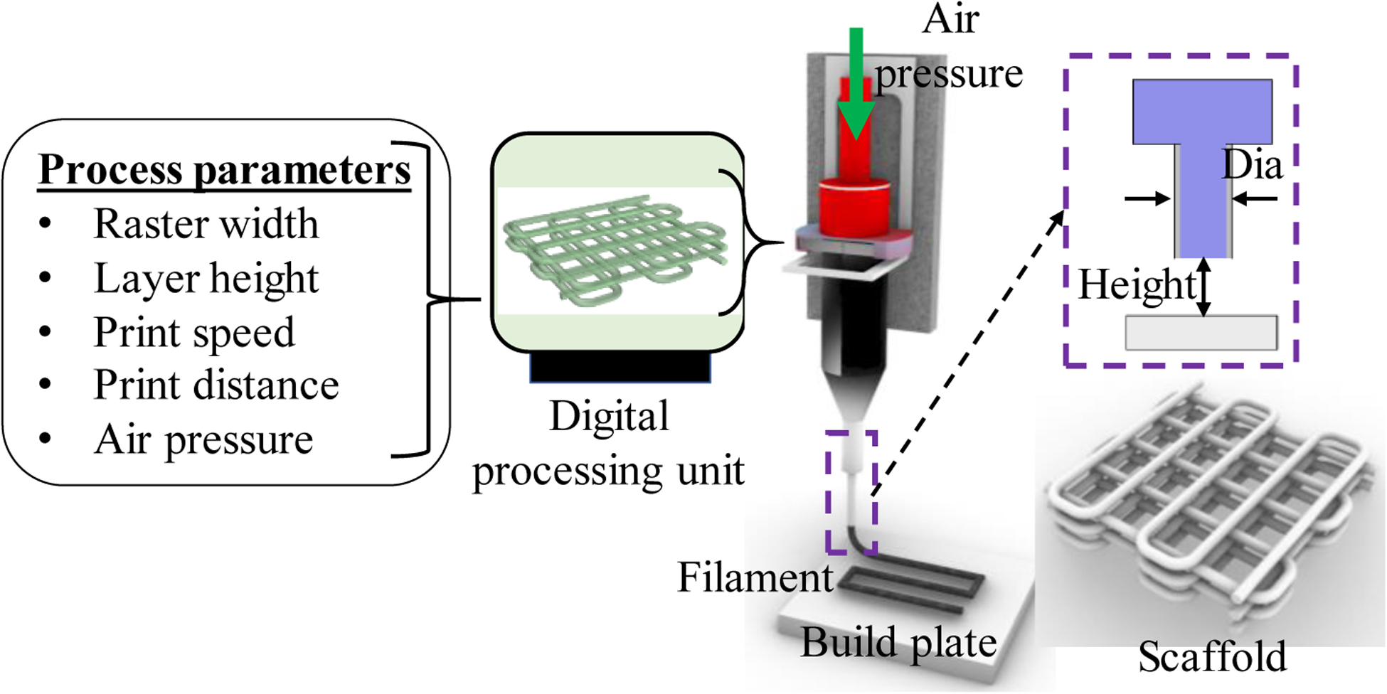
Processing the vectorized tool-path and printing the scaffold.
2.4. Identification of cell viability
The cell viability and biocompatibility of the encapsulated cells are conducted using LIVE/DEAD assay after the printing and at different time periods. Following the manufacturers’ protocol, ReadyProbes™ Cell Viability Imaging Kit, Blue/Green (Thermofisher, Waltham, MA, USA) is used. Cell encapsulated scaffold is imaged using Lionheart FX automated live-cell imager (Biotek, Winooski, VT, USA). Using 50 μm layer thickness, the z-stack images are captured. The protocol is defined accordingly, and the beacon (n = 5) is selected randomly. Laser power and other detector parameters are kept constant throughout the imaging of the different beacons. The percentage of cell viability is determined with the ratio of the total number of live cells to the total number of cells presented in the focused area.
2.5. Statistical analysis
The data are presented as a mean ± standard deviation. The evaluation of the statistical significance of the difference of various factors is conducted at a significance level of p = 0.05 with a two-way ANOVA. Statistical software Minitab 18.0 and Origin Pro 5.0 are used to do quantitative and graphical analysis.
3. Result and Discussion
3.1. Rheological properties
The rheological properties, i.e., viscosities, shear stress of bio-ink with alginate and CMC compositions are assessed by different rheological measurements. The impact of the different concentrations of CMC on rheological behavior with respect to the shear rate are determined by the following tests.
3.1.1. Shear-thinning properties
The impact of the different CMC concentrations on rheological behavior with respect to the shear rate is determined by the following tests shown in Figure 4. As the viscosity decreases with increasing the shear rate, all the compositions have shear thinning properties. However, the addition of CMC with suspension increases the viscosity as well as the shear stress. Zero-shear viscosity value of composition A4C4 increases almost from 1 Pa.S to 522 Pa.S compared to A4C0. Carboxylation of cellulose increases the number of carbonyl groups in CMC. Therefore, increasing the weight percent of CMC increases the overall cross-linking rate of the composition.
Figure. 4.
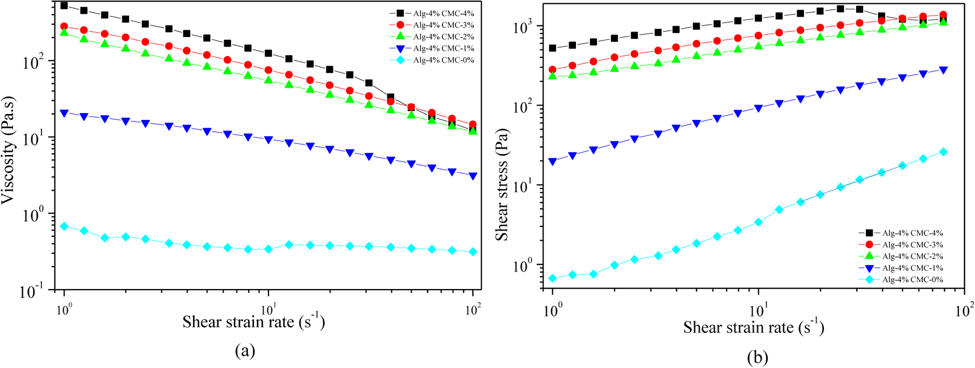
Evaluation of shear-thinning behavior of hydrogels: (a) Viscosity vs shear strain rate and (b) Shear stress vs. shear strain rate.
3.1.2. Loss tangent
The amplitude sweep test for the hydrogel compositions measured at 1 Hz is represented the outcome of G′ and G″ vs. shear strain (%) in Figure 5. It shows that increasing the percentage of CMC transforms the physical state from liquid-like to solid-like. With 0–2% of CMC, the value of G″ dominates G′ at each shear strain. Thereby, the liquid-like state is persisted for these two hydrogel compositions at our range of strain rate. With increasing the amount of CMC in the suspension (3% and 4%), G′dominates G″ up to a certain level of shear strain and then intersects. This intersection defines the linear viscoelastic range (LVR), which determines the limit at which the suspension preserves the sedimentation without permanent deformation. At the LVR region, the composition resembles the solid-like behavior. After the intersecting point, both moduli are decreased with the dominancy of G″ , i.e. the liquid-like phase causing the material to flow. This information is helpful to understand the relationship between extrusion pressure and material flow. The effective pressure must suppress this LVR strain rate to extrude the material through the nozzle. In the co-existence of liquid and solid-like phase, increasing the percentage of CMC pushes the LVR boundary as shown in Figure 5 (iii-v). Dynamic mechanical loss tangent (tanδ = G″/G′) is also determined to represent the data. Loss tangent value smaller than 1 predominantly reflects the elastic behavior, and greater than 1 predominantly indicates viscous behavior. It is clear from the Figure 5 (vi) that alginate with 4% CMC shows solid-like behavior up to 60% shear strain. The shear rate for A4C4 from Table 1 is greater than the shear strain for corresponding LVR, which informs the ability of this composition to flow through the nozzle.
Figure. 5.
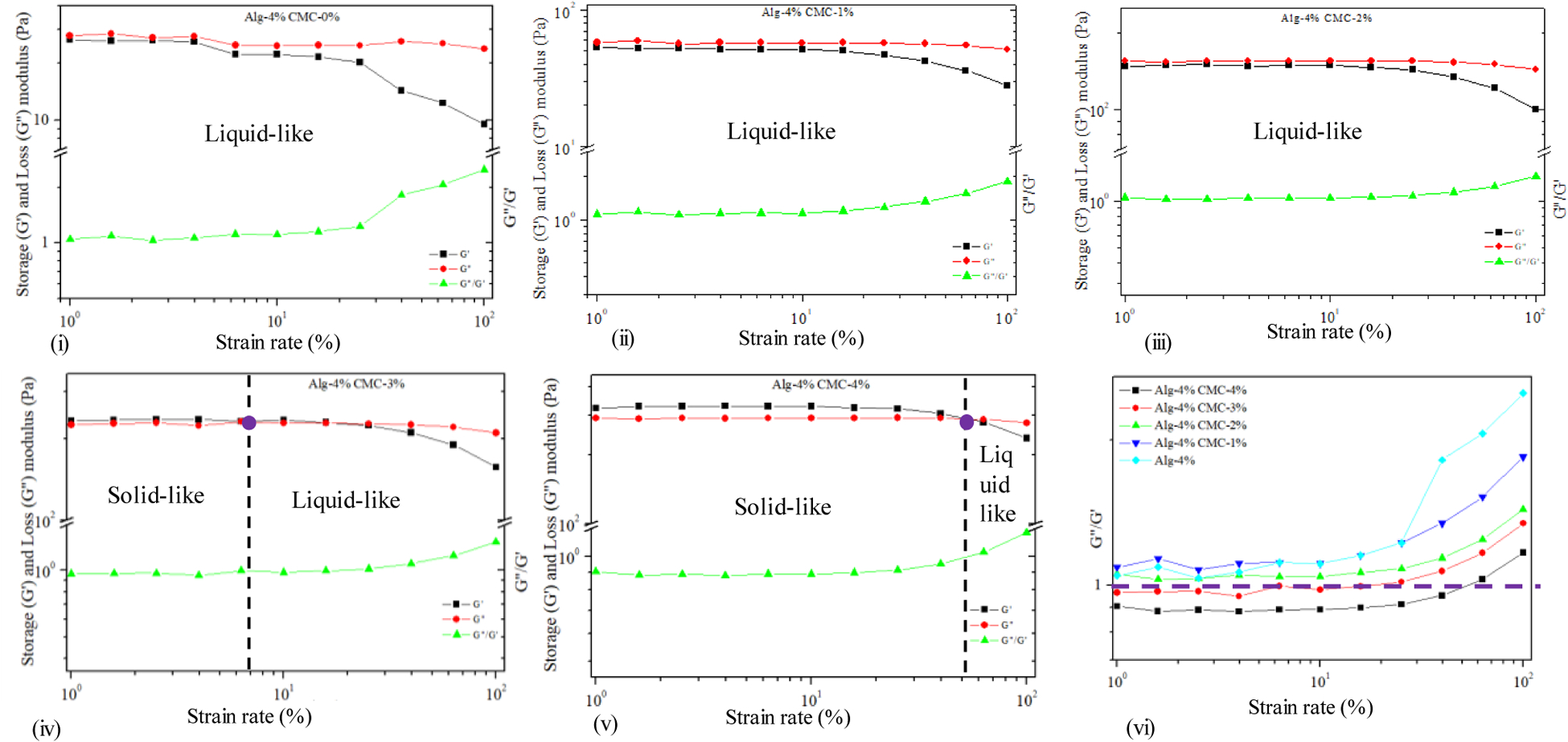
Dynamic strain sweep test for hybrid hydrogel composition.
3.1.3. Hysteresis loop and recovery of the hydrogel
3-interval-thixotropy-tests are also conducted on our compositions to determine the post-printing behavior. In this test, the first interval imitates the at-rest state of sample, the second interval resembles the hydrogel decomposition under high shear, and third interval reflects the structure retention after hydrogel extrusion. The stress-shear rate loop shown in Figure 6(b) demonstrates the shear history of alginate with 4% CMC. A stress is applied on the at-rest hydrogel, which breaks down the initial network structures of the hydrogel. After the hydrogel is extruded through the nozzle, due to the shear force, the bond between the polymer chain is disrupted. After the extrusion, the pressure is released, and the internal network bond starts recovering. In most cases, when the shear is released, the stress path lags, forming a hysteresis loop as shown in Figure 6(b). The area within the hysteresis loop signifies the energy consumed in the internal network breakdown. Figure 6(b) indicates that alginate with 4% CMC consumes more energy to break down the internal network than other compositions. The hydrogels’ recovery rate is determined from the hysteresis loop as shown in Figure 6(c). After extruding hydrogel through the nozzle, it takes time to recover the internal broken polar bonds. In most cases, when the shear is released, a portion of the bond remains irrecoverable. Therefore, the recovery rate remains less than 100%. With increasing the percentage of solid content, it might be difficult to recover the broken hydrogen or other polar bonds. Therefore, A4C4 shows a relatively lower recovery rate than low solid content compositions.
Figure. 6.
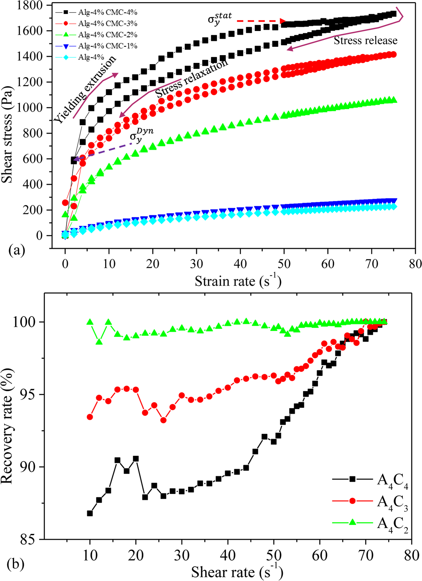
Result of 3-Interval-thixotropic-tests (a) for all compositions and (b) recovery rate of various compositions.
Following the rheological result, we calculated the shear-thinning coefficients, n, and K from the linear regions of graphs for Equation 1. We found n<1 for all the compositions, which implies that all the compositions demonstrate shear thinning behavior, ensuring their printability. The actual filament width indicates that with increasing the percentage of CMC, the filament width decreases. Filaments fabricated with compositions A4C3, A4C2, A4C1, and A4C0 showed almost 16%, 31%, 61%, and 89% more width than A4C4 indicates A4C4 has better shape holding capacity. The velocity correction factor and the corresponding average velocity is calculated based on this change in the filament width with respect to the nozzle diameter. The values of n, K, and average velocity are used to estimate the shear rate in the nozzle during extrusion using Equation 2. The viscosity and shear stresses are calculated using Equations 1 and 3, respectively. The results are shown in Table 1.
Table 1 shows that with the increase in solid content, the correction factor gets smaller. Additionally, the value of K increases with the increase in solid content so as the viscosity. Their value pattern suggests that higher solid content helps to maintain the shape fidelity of the structure. The shear rate value signifies that the rate at which the material passes the nozzle, which correlates the shear stress experienced by the material. When the material is preserving the internal bonds during the extrusion, a lower shear rate will be observed. At a higher shear rate, the internal bonds are disrupted quickly, and the encapsulated cells are exposed to the shear stress, which may cause the cell boundary rupture. Thus, the composition with a lower shear rate will preserve the cell better, which may be the reason for better cell viability.
3.2. Extrusion pressure and cell viability
The theoretical calculation of the velocity across the nozzle’s cross-section is estimated using Equation 4 as shown in Figure 7 (a). The parameters are determined from the rheological result in the previous section. The corresponding shear rate and shear stress are estimated using Equations 2 and 3 and are plotted in Figures 7(b) and 7(c), respectively. As shown in Figure 7(a), the velocity increases towards the nozzle center, where the shear rate and corresponding shear stress decrease towards the center. The shear rate and related shear stress are maximum at the nozzle wall.
Figure. 7.
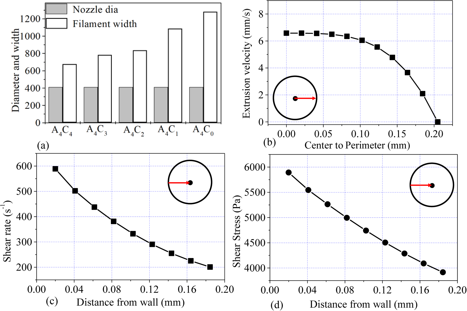
(a) Filament width of various compositions, (b) distribution of velocity from the center to the radius, (c) distribution of shear rate from the nozzle wall towards the center, and (d) distribution of corresponding shear stress from the nozzle wall towards the center.
To investigate the effect of the extrusion pressure and its spatial distribution, we printed HEK 293 cell with A4C4 composition at 8 psi and 12 psi applied pressure. The shear stress calculation indicates that cells will experience more shear stress near the nozzle wall. Therefore, we expect that the accounted cell viability near the wall will be lower across the cross-section of a deposited filament. Figure 8 shows more dead cells are at the edge of the deposited filament, where live cells are increasing towards the center of the filament. This phenomenon is also tested by visualizing the filament cross-section deposited at 8 psi and 12 psi as shown in Figure 9 and Figure 10. The total cross-sectional area is divided into three equal zone and defines as an outer zone, middle zone, and inner zone. The percentage of the live cell in the outer zone is 24.49% and 29.1% wherein the inner zone is 45% and 37.7% of the overall live cell at 8 psi and 12 psi, respectively. On the other hand, the percentage of the dead cell at the outer zone is 50% and 44.8% compared to 18.39% and 23.3% in the overall dead cell’s inner zone at 8 psi and 12 psi, respectively. We attributed this spatial variation of live and dead to the shear stress distribution.
Figure. 8.
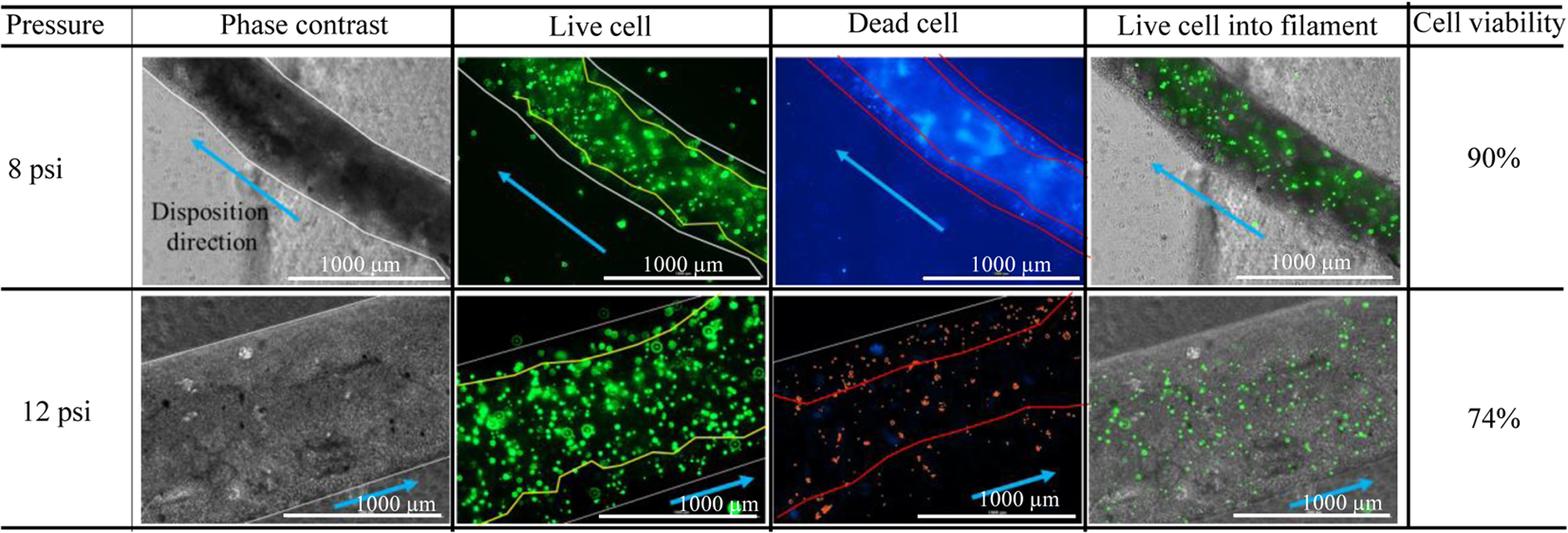
Demonstration of the presence of live/dead cell into deposited filament.
Figure. 9.

Comparison of the presence of live/dead cell on the cross-section of a filament deposited at 8 psi.
Figure. 10.

Comparison of the presence of live/dead cell on the cross-section of a filament deposited at 12 psi. (bar = 1000 μm)
3.3. Cell viability
Scaffold with a dimension of 10mm×10mm×2mm and raster width of 2 mm was fabricated using this cell-laden hydrogel. The cell viability of those cell lines into the scaffold was determined after 15 incubation days as shown in Figure 11(a). All the cell lines show an almost similar amount of cell viability (around 90%) as shown in Figure 11(b). This phenomenon indicates good survivability of different type of cells into this material composition.
Figure. 11.
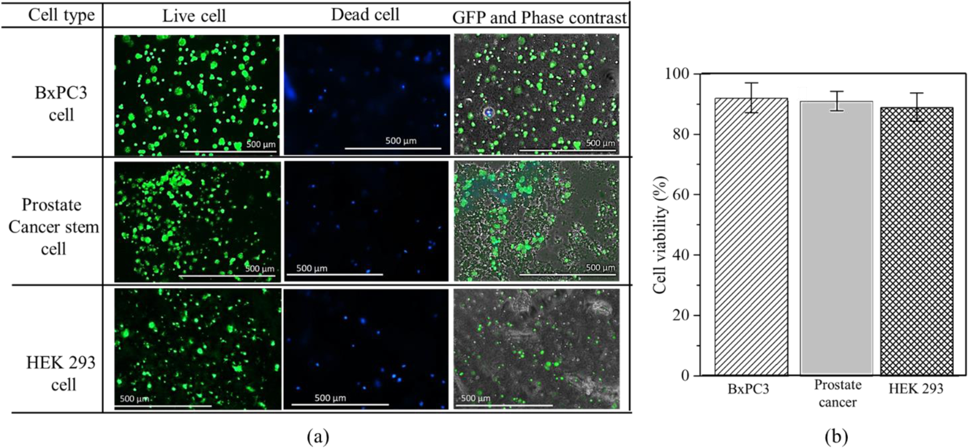
(a) Cell survivability of various cell line into 4% (w/v) Alg-4% (w/v) CMC hydrogel material (b) Cell viability of various cell line.
Moreover, the morphology of HEK 293 and BxPC3 cell lines are analyzed and compared after 15 days into A4C4 as shown in Figure 12. Carboxymethylcellulose (CMC), a high-molecular-weight polysaccharide, is one of the most common viscous and mucoadhesive polymers. CMC is a polymer of glucopyranose subunits, which is a predominant form of glucose in solution. It is demonstrated that CMC can bind directly to corneal epithelial cell through glucose receptor GluT-1 [46]. In this present study, since the HEK 293 is an epithelial-like cell, the matrix protein i.e. fibronectin and collagen secreted from this cell bind with the CMC surface which result CMC-fibronectin/collagen complex. This phenomenon may facilitate the attachment of HEK 293 cells with the proposed hybrid hydrogel and exhibits the cell phenotype as shown in Figure 12 (a). On the other hand, by nature BxPC3 has rounded shape cell morphology and the vendor for this cell line specifies them to be rounded. Hence, this cell line doesn’t show any change in morphology after 15 days of the incubation period, as shown in Figure 12 (b).
Figure. 12.
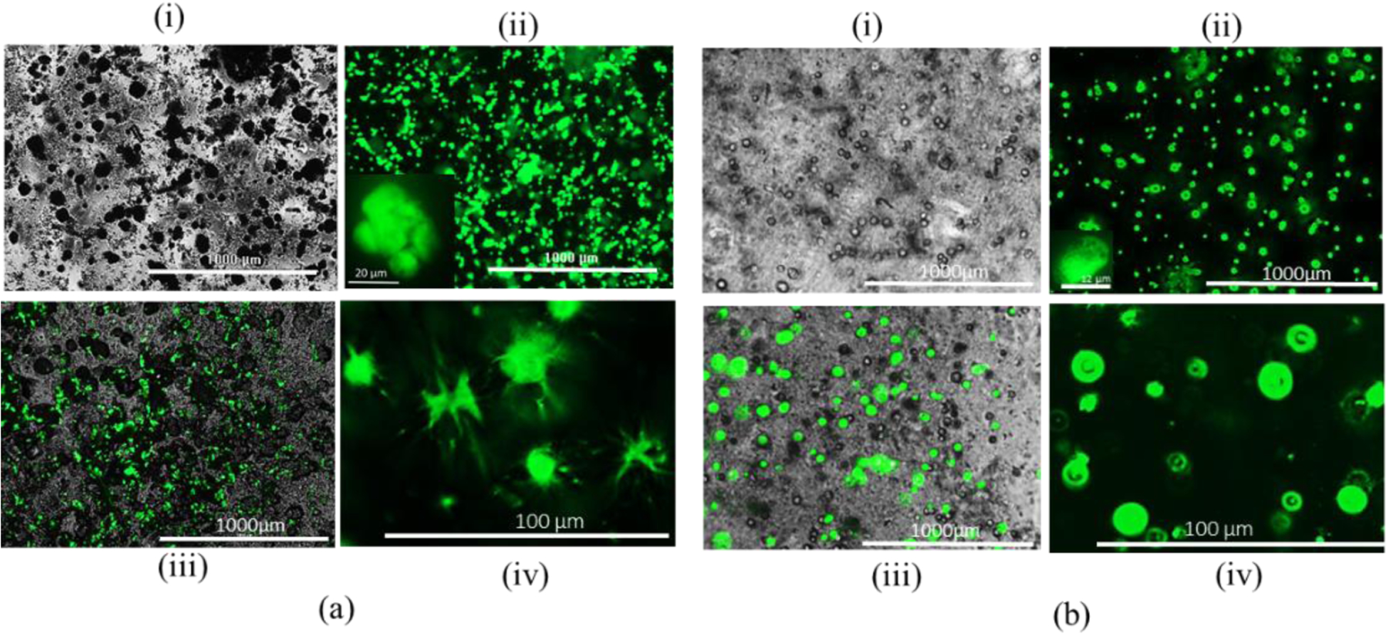
HEK 293 cell morphology: (a) Cell laden alginate-CMC and (b) Cell laden alginate: (i) Phase, (ii) GFP, (iii) Merging of phase and GFG (iv) Cell morphology.
3.4. Scaffold fabrication
Based on the rheological analysis, A4C4 has better extrudability than other compositions. Compositions were loaded into the dispensing syringe and extrude with 8 psi pressure to observe the filament-forming ability as shown in Figure 13 (a). These figures suggest that A4C4 creates the filament with proper gelation, where A4C0 forms droplets due to under-gelation. All the compositions were deposited on the print bed to identify the shape-holding capacity where A4C4 preserves a better filament shape with less diffusion, as shown in Figure 13 (b). Some complex bi-layer scaffolds with various tool-path directions are fabricated, as shown in Figure 13 (c, d, f, g) to demonstrate the capability to hold the shape fidelity. Moreover, scaffolds having higher Z-height i.e., in cm-scale are fabricated following tool-path directions of 0°-45°-90° and 0°-90° respectively, with the same composition of the material as shown in Figure 13(e,h). In both cases, the candidate composition shows better printability and shape fidelity of the fabricated scaffolds.
Figure. 13.
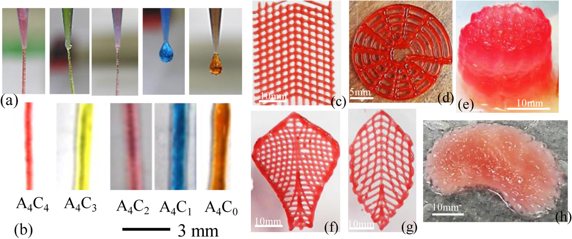
(a-b) Printability of different compositions (c,d,f,g) Fabricating complex bi-layer scaffold and (e,h) Fabricating scaffold having large Z-height with 4%(w/v) Alg-4%(w/v) CMC.
The overall cell viability of the scaffolds fabricated by the extrusion-based 3D bio-printing technique depends on the shear stress experienced by encapsulated cells. Equations 1–4 interlinked the resultant shear stress with material and process parameters (i.e., viscosity, applied pressure, and nozzle diameter). Table 2 shows a comparison between the proposed bio-ink and the existing bio-ink in terms of various factors. Fabricating scaffolds with a higher percentage of solid content may ensure a better shape fidelity [54, 55] as it increases the viscosity of the composition. However, due to the required higher dispensing pressure, small nozzle diameter, and corresponding higher shear stress, the overall cell viability can be negatively affected. Thus, the viscosity of the effective bio-ink must be harmonized with the nozzle geometry to maintain the proper printability and shape fidelity, while cushioning the cell for biocompatibility. The solid content of 9% (w/v) was used to fabricate the scaffold with an applied pressure of approximately 14 psi, which ensured the fabrication of a large scaffold. However, the cell encapsulated scaffold showed relatively less cell viability, e.g., 70–75% [47]. Cell-laden scaffolds were fabricated using 9 % solid content using 700 nozzle diameter and 13.5 psi applied pressure [50]. It showed 85% cell viability in 4 incubation days with 300% higher filament width with respect to the nozzle size used. In separate work, 168% deviation of the filament width has been reported with 15% solid content composition and 14.5 psi pressure [51].
Table. 2.
Comparison of bio-ink reported in literature.
| Solid content (%) | Components | Viscosity range (Pa.S) | Applied pressure (psi) | Nozzle size (μm) | Shear rate (s−1) | Shear stress (Pa) | Printability and shape fidelity | Cell viability (%) | Ref. |
|---|---|---|---|---|---|---|---|---|---|
| 9(3/3/3) | Lap/alg/MC | 1000–100 | 11.6–13.78 | 410 | NA | NA | Better | 70–75 (21 days) | [47] |
| 9 (8/1) | Alg/CaCl2 | 300–1 | 50 | 125 | 575 | 1786 | Better | NA | [32] |
| 2.5(2.25/.25) | NFC/Alg | 800–5 | 2.9–8.7 | 610 | NA | NA | Good | 85.7 (2 days) | [48] |
| 2(1.5/.5) | Alg/CaCl2 | NA | 20 | 250 | NA | 105 | Good | 76 (21 days) | [49] |
| 9(5/2/2) | Gel/Alg/Cel | 270–9 | 13.5 | 700 | 774 | 1573 | Good | 85 (4 days) | [50] |
| 15(10/5) | CNC/Gel | 240–10 | 14.5 | 410 | 815 | 1792 | Poor/Good | NA | [51] |
| 10(8/2) | Gel/κ-carrageenan | NA | NA | 250 | NA | 13500 | Good | 90 (2 days) | [52] |
| 3 | hdECM | 45–0.9 | NA | 260 | NA | NA | Poor | 95 (7 days) | [53] |
| 8(4/4) | Alg/CMC | 522–30 | 8 | 410 | 182 | 3693 | Better | 90 (15 days) | Proposed |
Several works have reported using partially cross-linked alginate for bio-ink and fabricating the cell encapsulated scaffold (Table 2). Good printability and shape fidelity was achieved with a range of applied pressure from 3 to 20 psi [32, 49, 56]. However, due to a different range of shear rate and corresponding shear stress and viscosity, the cell viability was reported between 76 to 85%. Low viscosity bio-ink can achieve more than 95% cell viability due to less solid content. However, the fabricated scaffold can experience poor shape fidelity [53]. Therefore, it is clear from this comparison that single parameters such as viscosity, or nozzle diameter, or applied pressure should not be the only defining factor to identify the optimum bio-ink. A combination of those factors should define the functionality of the bio-ink ensuring proper printability, shape fidelity, and cell viability.
A material composition with comparatively less solid content with better viscosity is required to maintain the fabricated scaffold’s printability and shape fidelity. Simultaneously, lower shear rate and corresponding shear stress during extrusion are important to ensure better cell viability. Our proposed roadmap for bio-ink optimization demonstrates a successful implementation of printability, shape fidelity, and cell-viability simultaneously. For example, when we extruded the HEK 293 cell encapsulated bio-ink using 12 psi applied pressure, it increased 112% shear rate (385.26 s−1) which is equivalent to 36% increase of shear stress (5015 Pa) at the wall compared to 8 psi pressure. This increment of shear stress negatively affected the encapsulated cell and reduced the overall cell viability to 74% instead of 90%. Results from the existing literature are compiled in Table 2 and compared with our proposed bio-ink to illustrate the contrast among the troika which also supports our findings. Very few literatures have reported the relationship between the corresponding shear stress and cell viability. The methodology presented in this paper will provide deeper insight in designing the bio ink in extrusion based bio printing. The knowledge will guide the community to optimize the functionality of bio ink with minimal experimentation and better coherence.
4. Conclusion
This research analyzed the rheological properties along with the printing process parameter to determine the shear stress exerted on the cell passing through the bio-printer nozzle. The information is used to design the bio-ink for extrusion-based bio-printing which is also validated for bio-ink functionality (i.e., printability, shape fidelity, and cell viability). The methodology is implemented with a cell-laden hybrid hydrogel (alginate and CMC) as the bio-ink. We determined the effect of viscosity, shear stress, storage modulus, loss modulus, and recovery rate for the hybrid hydrogel material. The effect of rheological properties on a single filament and across the cross-sectional area of a filament is also analyzed. Three cell lines (HEK 293, BxPC3, and prostate cancer cells) were considered for bio-printing to investigate our research finding. The cells were able to sustain transient shear stress of 3.7 kPa and demonstrate 90% viability with our designed bio-ink. Simultaneously, the shape fidelity and printability matrices show its suitability for 3D bio-printing process. The outcome can assist the 3D bio-fabrication process in fabricating functional tissues and organs. We added 107 cells/ml to prepare the cell-lade bio-ink which is less than 3 (volume) %. Due to the presence of cells, the rheological data may vary in cell-laden bio-ink. However, we have not considered that variation in this paper which could be future work.
Acknowledgment
Financial support provided by National Science Foundation Grant # OIA-1355466, Department of Transportation US-DOT # 693JK31850009CAAP, and National Institute of Health under COBRE: CDTSPC Grant # P20GM109024 are acknowledged.
Footnotes
Publisher's Disclaimer: This is a PDF file of an unedited manuscript that has been accepted for publication. As a service to our customers we are providing this early version of the manuscript. The manuscript will undergo copyediting, typesetting, and review of the resulting proof before it is published in its final form. Please note that during the production process errors may be discovered which could affect the content, and all legal disclaimers that apply to the journal pertain.
Declaration of Interest Statement
The Author has no conflict of interest in this submitted paper.
Contributor Information
Md Ahasan Habib, Department of Sustainable Product Design and Architecture, Keene State College, Keene, NH.
Bashir Khoda, Department of Mechanical Engineering, The University of Maine Orono, ME, United States
References
- 1.Murphy SV and Atala A, 3D bioprinting of tissues and organs. Nature biotechnology, 2014. 32(8): p. 773–785. [DOI] [PubMed] [Google Scholar]
- 2.Jia W, et al. , Direct 3D bioprinting of perfusable vascular constructs using a blend bioink. Biomaterials, 2016. 106: p. 58–68. [DOI] [PMC free article] [PubMed] [Google Scholar]
- 3.Axpe E and Oyen ML, Applications of alginate-based bioinks in 3D bioprinting. International Journal of Molecular Sciences, 2016. 17(12): p. 1976. [DOI] [PMC free article] [PubMed] [Google Scholar]
- 4.Skardal A and Atala A, Biomaterials for integration with 3-D bioprinting. Annals of biomedical engineering, 2015. 43(3): p. 730–746. [DOI] [PubMed] [Google Scholar]
- 5.Zhao D, et al. , 3D printing of a titanium-tantalum Gyroid scaffold with superb elastic admissible strain, bioactivity and in-situ bone regeneration capability. Additive Manufacturing, 2021. 47: p. 102223. [Google Scholar]
- 6.Liang H, et al. , 3D-printed porous titanium scaffolds incorporating niobium for high bone regeneration capacity. Materials & Design, 2020. 194: p. 108890. [Google Scholar]
- 7.Koch L, et al. , Laser assisted cell printing. Current pharmaceutical biotechnology, 2013. 14(1): p. 91–97. [PubMed] [Google Scholar]
- 8.Devillard R, et al. , Cell patterning by laser-assisted bioprinting, in Methods in cell biology. 2014, Elsevier. p. 159–174. [DOI] [PubMed] [Google Scholar]
- 9.Cui X, et al. , Thermal inkjet printing in tissue engineering and regenerative medicine. Recent patents on drug delivery & formulation, 2012. 6(2): p. 149–155. [DOI] [PMC free article] [PubMed] [Google Scholar]
- 10.Ozbolat IT and Hospodiuk M, Current advances and future perspectives in extrusion-based bioprinting. Biomaterials, 2016. 76: p. 321–343. [DOI] [PubMed] [Google Scholar]
- 11.Wang LL, et al. , 3D extrusion bioprinting of single-and double-network hydrogels containing dynamic covalent crosslinks. Journal of Biomedical Materials Research Part A, 2018. [DOI] [PMC free article] [PubMed] [Google Scholar]
- 12.Li Z, et al. , Tuning Alginate-Gelatin Bioink Properties by Varying Solvent and Their Impact on Stem Cell Behavior. Scientific Reports, 2018. 8(1): p. 8020. [DOI] [PMC free article] [PubMed] [Google Scholar]
- 13.He Y, et al. , Research on the printability of hydrogels in 3D bioprinting. Scientific reports, 2016. 6: p. 29977. [DOI] [PMC free article] [PubMed] [Google Scholar]
- 14.Ahlfeld T, et al. , A methylcellulose hydrogel as support for 3D plotting of complex shaped calcium phosphate scaffolds. Gels, 2018. 4(3): p. 68. [DOI] [PMC free article] [PubMed] [Google Scholar]
- 15.Jin Y, et al. , Self-Supporting Nanoclay as Internal Scaffold Material for Direct Printing of Soft Hydrogel Composite Structures in Air. ACS Applied Materials & Interfaces, 2017. 9(20): p. 17456–17465. [DOI] [PubMed] [Google Scholar]
- 16.Li H, et al. , 3D bioprinting of highly thixotropic alginate/methylcellulose hydrogel with strong interface bonding. ACS applied materials & interfaces, 2017. 9(23): p. 20086–20097. [DOI] [PubMed] [Google Scholar]
- 17.Ahn G, et al. , Precise stacking of decellularized extracellular matrix based 3D cell-laden constructs by a 3D cell printing system equipped with heating modules. Scientific Reports, 2017. 7(1): p. 8624. [DOI] [PMC free article] [PubMed] [Google Scholar]
- 18.Di Giuseppe M, et al. , Mechanical behaviour of alginate-gelatin hydrogels for 3D bioprinting. Journal of the mechanical behavior of biomedical materials, 2018. 79: p. 150–157. [DOI] [PubMed] [Google Scholar]
- 19.Mouser VH, et al. , Yield stress determines bioprintability of hydrogels based on gelatin-methacryloyl and gellan gum for cartilage bioprinting. Biofabrication, 2016. 8(3): p. 035003. [DOI] [PMC free article] [PubMed] [Google Scholar]
- 20.Tabriz AG, et al. , Three-dimensional bioprinting of complex cell laden alginate hydrogel structures. Biofabrication, 2015. 7(4): p. 045012. [DOI] [PubMed] [Google Scholar]
- 21.Kuo C, et al. , Printability of Hydrogel Composites Using Extrusion-Based 3D Printing and Post-Processing with Calcium Chloride. J Food Sci Nutr, 2019. 5: p. 051. [Google Scholar]
- 22.Chang R, Nam J, and Sun W, Effects of dispensing pressure and nozzle diameter on cell survival from solid freeform fabrication-based direct cell writing. Tissue Eng Part A, 2008. 14(1): p. 41–8. [DOI] [PubMed] [Google Scholar]
- 23.He Y, et al. , Research on the printability of hydrogels in 3D bioprinting. Sci Rep, 2016. 6: p. 29977. [DOI] [PMC free article] [PubMed] [Google Scholar]
- 24.Ouyang L, et al. , 3D printing of HEK 293FT cell-laden hydrogel into macroporous constructs with high cell viability and normal biological functions. Biofabrication, 2015. 7(1): p. 015010. [DOI] [PubMed] [Google Scholar]
- 25.Hong S, et al. , 3D printing of highly stretchable and tough hydrogels into complex, cellularized structures. Advanced Materials, 2015. 27(27): p. 4035–4040. [DOI] [PMC free article] [PubMed] [Google Scholar]
- 26.Wang N, et al. , Mechanical behavior in living cells consistent with the tensegrity model. Proceedings of the National Academy of Sciences, 2001. 98(14): p. 7765–7770. [DOI] [PMC free article] [PubMed] [Google Scholar]
- 27.Ludwig A, Kretzmer G, and Schügerl K, Determination of a “critical shear stress level” applied to adherent mammalian cells. Enzyme and Microbial Technology, 1992. 14(3): p. 209–213. [DOI] [PubMed] [Google Scholar]
- 28.Clark EA and Brugge JS, Integrins and signal transduction pathways: the road taken. Science, 1995. 268(5208): p. 233. [DOI] [PubMed] [Google Scholar]
- 29.Ouyang L, et al. , Effect of bioink properties on printability and cell viability for 3D bioplotting of embryonic stem cells. Biofabrication, 2016. 8(3): p. 035020. [DOI] [PubMed] [Google Scholar]
- 30.Blaeser A, et al. , Controlling shear stress in 3D bioprinting is a key factor to balance printing resolution and stem cell integrity. Advanced healthcare materials, 2016. 5(3): p. 326–333. [DOI] [PubMed] [Google Scholar]
- 31.Chang R, Nam J, and Sun W, Effects of dispensing pressure and nozzle diameter on cell survival from solid freeform fabrication–based direct cell writing. Tissue Engineering Part A, 2008. 14(1): p. 41–48. [DOI] [PubMed] [Google Scholar]
- 32.Paxton NC, et al. , Proposal to Assess Printability of Bioinks for Extrusion-Based Bioprinting and Evaluation of Rheological Properties Governing Bioprintability. Biofabrication, 2017. [DOI] [PubMed] [Google Scholar]
- 33.Habib A, et al. , 3D Printability of Alginate-Carboxymethyl Cellulose Hydrogel. Materials (Basel), 2018. 11(3). [DOI] [PMC free article] [PubMed] [Google Scholar]
- 34.Malda J, et al. , 25th anniversary article: engineering hydrogels for biofabrication. Advanced materials, 2013. 25(36): p. 5011–5028. [DOI] [PubMed] [Google Scholar]
- 35.Sun J and Tan H, Alginate-based biomaterials for regenerative medicine applications. Materials, 2013. 6(4): p. 1285–1309. [DOI] [PMC free article] [PubMed] [Google Scholar]
- 36.Han Y and Wang L, Sodium alginate/carboxymethyl cellulose films containing pyrogallic acid: physical and antibacterial properties. Journal of the Science of Food and Agriculture, 2017. 97(4): p. 1295–1301. [DOI] [PubMed] [Google Scholar]
- 37.Tongdeesoontorn W, et al. , Effect of carboxymethyl cellulose concentration on physical properties of biodegradable cassava starch-based films. Chemistry Central Journal, 2011. 5(1): p. 6. [DOI] [PMC free article] [PubMed] [Google Scholar]
- 38.Colosi C, et al. , Microfluidic Bioprinting of Heterogeneous 3D Tissue Constructs Using Low-Viscosity Bioink. Advanced Materials, 2016. 28(4): p. 677–684. [DOI] [PMC free article] [PubMed] [Google Scholar]
- 39.Chung JH, et al. , Bio-ink properties and printability for extrusion printing living cells. Biomaterials Science, 2013. 1(7): p. 763–773. [DOI] [PubMed] [Google Scholar]
- 40.Jia J, et al. , Engineering alginate as bioink for bioprinting. Acta biomaterialia, 2014. 10(10): p. 4323–4331. [DOI] [PMC free article] [PubMed] [Google Scholar]
- 41.Schütz K, et al. , Three-dimensional plotting of a cell-laden alginate/methylcellulose blend: towards biofabrication of tissue engineering constructs with clinically relevant dimensions. Journal of tissue engineering and regenerative medicine, 2017. 11(5): p. 1574–1587. [DOI] [PubMed] [Google Scholar]
- 42.Therriault D, White SR, and Lewis JA, Rheological behavior of fugitive organic inks for direct-write assembly. Applied Rheology, 2007. 17(1): p. 10112–11411. [Google Scholar]
- 43.Bruneaux J, Therriault D, and Heuzey M-C, Micro-extrusion of organic inks for direct-write assembly. Journal of Micromechanics and Microengineering, 2008. 18(11): p. 115020. [Google Scholar]
- 44.Hanson Shepherd JN, et al. , 3D microperiodic hydrogel scaffolds for robust neuronal cultures. Advanced functional materials, 2011. 21(1): p. 47–54. [DOI] [PMC free article] [PubMed] [Google Scholar]
- 45.Billiet T, et al. , The 3D printing of gelatin methacrylamide cell-laden tissue-engineered constructs with high cell viability. Biomaterials, 2014. 35(1): p. 49–62. [DOI] [PubMed] [Google Scholar]
- 46.Garrett Q, et al. , Carboxymethylcellulose binds to human corneal epithelial cells and is a modulator of corneal epithelial wound healing. Investigative ophthalmology & visual science, 2007. 48(4): p. 1559–1567. [DOI] [PubMed] [Google Scholar]
- 47.Ahlfeld T, et al. , Development of a clay based bioink for 3D cell printing for skeletal application. Biofabrication, 2017. 9(3): p. 034103. [DOI] [PubMed] [Google Scholar]
- 48.Jessop ZM, et al. , Printability of pulp derived crystal, fibril and blend nanocellulose-alginate bioinks for extrusion 3D bioprinting. Biofabrication, 2019. 11(4): p. 045006. [DOI] [PubMed] [Google Scholar]
- 49.Khalil S and Sun W, Bioprinting endothelial cells with alginate for 3D tissue constructs. Journal of biomechanical engineering, 2009. 131(11): p. 111002. [DOI] [PubMed] [Google Scholar]
- 50.Erkoc P, et al. , 3D Printing of Cytocompatible Gelatin-Cellulose-Alginate Blend Hydrogels. Macromolecular Bioscience, 2020. 20(10): p. 2000106. [DOI] [PubMed] [Google Scholar]
- 51.Jiang Y, et al. , Rheological behavior, 3D printability and the formation of scaffolds with cellulose nanocrystals/gelatin hydrogels. Journal of Materials Science, 2020. 55(33): p. 15709–15725. [Google Scholar]
- 52.Li H, Tan YJ, and Li L, A strategy for strong interface bonding by 3D bioprinting of oppositely charged κ-carrageenan and gelatin hydrogels. Carbohydrate polymers, 2018. 198: p. 261–269. [DOI] [PubMed] [Google Scholar]
- 53.Jang J, et al. , Tailoring mechanical properties of decellularized extracellular matrix bioink by vitamin B2-induced photo-crosslinking. Acta biomaterialia, 2016. 33: p. 88–95. [DOI] [PubMed] [Google Scholar]
- 54.Ribeiro A, et al. , Assessing bioink shape fidelity to aid material development in 3D bioprinting. Biofabrication, 2017. [DOI] [PMC free article] [PubMed] [Google Scholar]
- 55.Li VC-F, et al. , Direct Ink Write (DIW) 3D Printed Cellulose Nanocrystal Aerogel Structures. Scientific Reports, 2017. 7(1): p. 8018. [DOI] [PMC free article] [PubMed] [Google Scholar]
- 56.Athirasala A, et al. , A dentin-derived hydrogel bioink for 3D bioprinting of cell laden scaffolds for regenerative dentistry. Biofabrication, 2018. 10(2): p. 024101. [DOI] [PMC free article] [PubMed] [Google Scholar]


