Abstract
Objective:
To determine the differences between manual and cephalometric measurements on different sections of the human skull, which were obtained using computer-assisted three-dimensional (3D) analysis and conventional two-dimensional (2D) techniques.
Materials and Methods:
Measurements were carried out on 13 dry human skulls, then 2D cephalograms and 3D computed tomographic (CT) images were obtained. Anatomic landmarks were determined and marked with clay before CT images were taken, and the same landmarks were marked with the help of metallic balls and pins for lateral and frontal cephalograms. Manual, lateral/frontal cephalometric, and computer-assisted 3D cephalometric measurements were compared statistically. One-way analysis of variance and Tukey Honestly Significant Difference tests were used to compare the results among the groups.
Results:
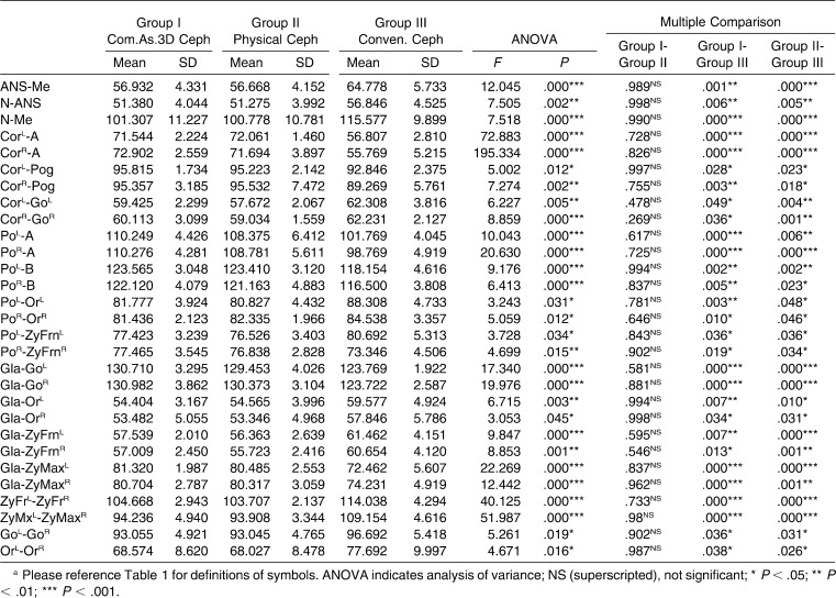
All measurements were statistically insignificant between the computer-assisted 3D and manual measurements. On the other hand, the differences between the conventional 2D and the manual measurements were statistically significant. The greatest amount of magnification was found at the Nasion-Menton distance (14.6%), which was located at the farthest distance from the central x-ray beam in the lateral cephalogram (P < .01). For the same reason, the greatest enlargement (16.2%) was observed in the distance between the zygomaticomaxillary sutures on the conventional frontal cephalogram (P < .01).
Conclusions:
The computer-aided 3D cephalometric measurements were found to be more accurate than the conventional cephalometric measurements. The results revealed that 3D cephalometric measurements were consistent with the manual measurements. In addition, the magnification and distortion might limit the results of conventional cephalometric measurements.
Keywords: Dry skull, Three-dimensional cephalometry, Conventional cephalometry
INTRODUCTION
The craniofacial skeleton is one of the most complex regions of the human body and a difficult area to analyze. Cephalometric radiography is used to describe the morphology and growth of the craniofacial skeleton, to predict growth, to develop treatment plans, and to evaluate treatment results. On the other hand, reliable and accurate evaluation is difficult because of the inherent geometric magnification, distortion, and super-positioning of craniofacial structures.1–6 These shortcomings of conventional imaging techniques led to the development of alternative cephalometric analysis approaches.
Three-dimensional (3D) imaging techniques are becoming increasingly popular and have allowed for the development of new possibilities in the arena of orthodontic diagnosis and treatment assessment.7,8 The accuracy of 3D-rendered images had been previously evaluated,9,10 and the findings showed that direct 3D measurements were highly accurate, with no significant discrepancies from manual measurements. 3D imaging techniques comprise a noninvasive method. One of the best examples is cone beam tomography (CBCT). According to Swennen and Schutyser,11 conventional computed tomography (CT) has a 0.93-mSv effective dose, whereas CBCT offers an 0.05-mSv effective dose for imaging of the cranium.
Recently, Materialise's Interactive Medical Image Control System (Mimics, Materialise, Leuven, Belgium) has become one of the most common forms of 3D cephalometry software in orthodontics.12 Nevertheless, to date, the accuracy of 3D cephalometric analysis has not been compared with that of manual measurements.
The aims of this study were to determine the accuracy of manual and cephalometric measurements, which were obtained by a computer-assisted 3D analysis system and conventional two-dimensional (2D) system, and to compare the differences between these measurements on different sections of human skull.
MATERIALS AND METHODS
Thirteen human adult dry skulls, on which landmarks were designated with clay markers (Figures 1 and 2) were scanned with a Philips MX 8000 IDT Multi-slice CT System (V 2.5; Philips Medical Systems, The Netherlands) with a high-resolution bone algorithm, 512 × 512 matrix, 120 kV, and 100 mA. Axial scans were obtained with a 1-mm slice thickness and parallel to the Frankfurt horizontal plane. The 3D model of the axial images was reconstructed using Mimics v12.01 (Materialise) software, and 3D cephalometric analyses were performed (Figures 3 and 4).
Figure 1.
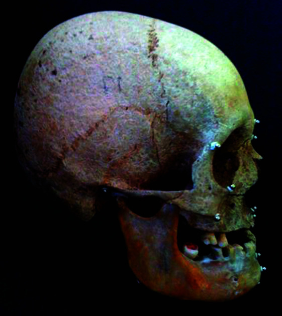
Lateral view of the dry skull.
Figure 2.
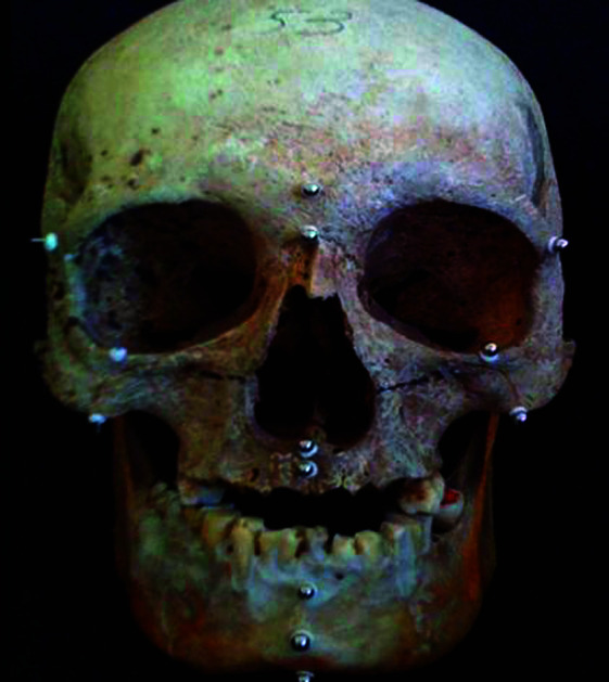
Frontal view of the dry skull.
Figure 3.
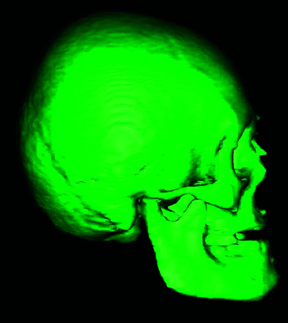
Lateral view of computer-assisted 3D image of the dry skull.
Figure 4.
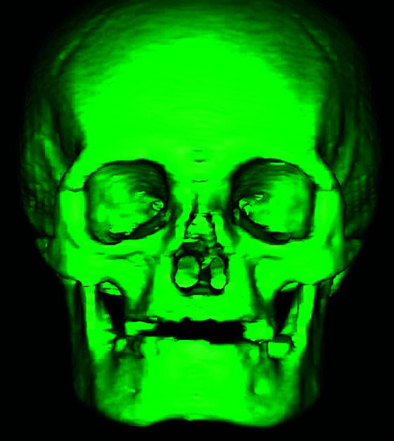
Frontal view of computer-assisted 3D image of the dry skull.
Standard lateral and frontal cephalograms of the dry skulls, on which clay markers were replaced with metallic balls and pins, were taken by Odontorama PC (85kV, 10 mA; Trophy Radiologie, Croissy-Beauborg, France) (Figures 5 and 6). In order to avoid the measurement errors, the diameter of clays and balls and the length of the pins were adjusted to 3 mm. Since the slice thickness was less than 1 mm, 3D images of the markers were achieved accurately. All metric measurements were made between the outermost points of balls and pins during manual and 3D virtual model measurements. All measurements on 2D radiograms were made between the center points of pins and balls.
Figure 5.
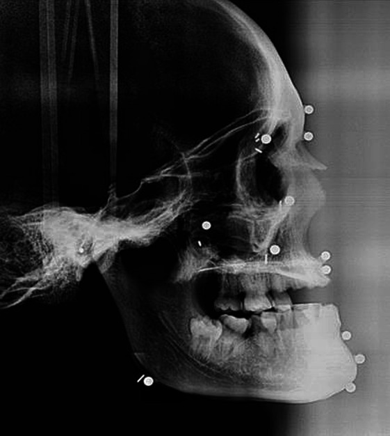
Conventional lateral cephalogram of the dry skull.
Figure 6.
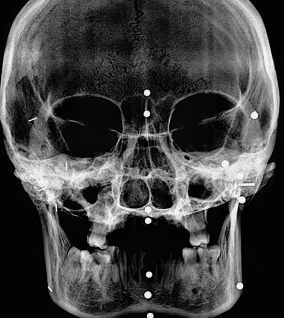
Conventional frontal cephalogram of the dry skull.
A 6-inch digital caliper (MSI-Viking Gage, Duncan, SC), accurate to 0.001 inch and to a resolution of 0.0005 inch, was used to measure the distance directly between the selected landmarks on dry skulls.
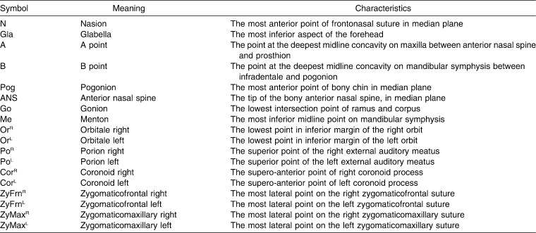
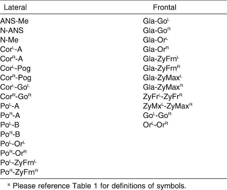
In all cephalometric analyses, 18 landmarks and 29 measurements (17 lateral and 12 frontal) were used (Figures 7 and 8; Tables 1 and 2).13 Measurements were evaluated in three groups, as follows: (1) group I: computer-assisted 3D cephalometric measurements; (2) group II: physical cephalometric measurements; and (3) group III: conventional 2D cephalometric measurements.
Figure 7.
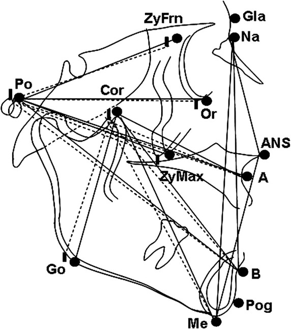
Landmarks and planes used in lateral cephalometric evaluation.
Figure 8.
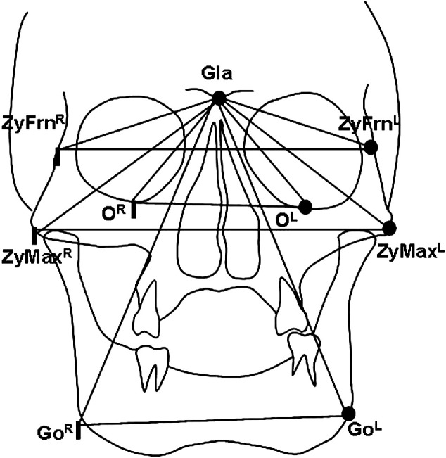
Landmarks and planes used in frontal cephalometric evaluation.
Table 1.
Landmarks Used in Cephalometric Analysis
Table 2.
Measurements Used in Cephalometric Analysisa
Statistical Method
All statistical analyses were performed using the SPSS software package (Statistical Package for Social Sciences for Windows, version 13.0, SPSS Inc, Chicago, Ill). Statistical significance was set to P < .05. The normality of data was analyzed with the Shapiro-Wilk's test. In order to compare the changes between the measurements in groups, one-way analysis of variance and Tukey Honestly Significant Difference tests were performed.
Method Error
Four weeks after the first measurements, all radiographs, 3D images, and dry skulls were remeasured by the same author. A paired-samples t-test was applied. The differences between the first and second measurements of the parameters were insignificant. Correlation analysis yielded the highest r value, 0.995, for the intergonial distance among the dry skull measurements and the lowest r value, 0.786, for the distance between right porion and A point among the conventional 2D cephalometric measurements. The error of the method was calculated using Dahlberg's formula. The values changed from 0.479 to 0.976 and were within acceptable limits.
RESULTS
Table 3 shows the descriptive statistics (mean and standard deviation) of cephalometric variables of all three groups (Group I: Computer Assisted 3 D Cephalometry, Group II: Physical Cephalometry, Group III: Conventional Cephalometry) and the statistical comparison of mean values. The comparison of the groups revealed statistically insignificant differences between the first and second groups. On the contrary, statistically significant changes were found between the second and third groups. The same statistically significant differences were also observed between the first and third groups.
Table 3.
Descriptive and Statistical Comparison of Groupsa
DISCUSSION
Imaging is one of the most widespread tools used to measure and record the size and form of craniofacial structure in orthodontics. The main goal of imaging is to replicate the anatomic truth to show the 3D anatomy. To reduce costs and risk, orthodontists routinely use 2D static imaging techniques to record the 3D anatomy of the craniofacial region.
Cephalograms have been widely used as clinical tools and research techniques. Because of the erroneous assumptions inherent in traditional 2D cephalometrics, use of this method for deriving clinical information as a basis for planning treatment has been questioned.14–16 The most significant issue is that a conventional head film is a 2D representation of a 3D object. Structures are displaced vertically and horizontally in proportion to their distance from the film or recording plane.
Cephalometric analyses are based on the assumption of a perfect superimposition of the right and left sides about the midsagittal plane, but this condition is observed infrequently because facial symmetry is rare.17 Another problem is attributed to radiographic projection error, which includes the size of magnification and the distortion pertaining to the film/patient/focus geometric relationships.18 This primarily refers to the differential magnification created by projection distance among the imaging device, recording device, and a 3D object. Manual data collection and processing in cephalometric analysis have been shown to have low accuracy and precision19 pertaining to ambiguity in locating anatomical landmarks as a result of the lack of well-defined outlines, hard edges, and shadows, as well as variations in patient position.20
In order to eliminate the disadvantages of conventional cephalometric evaluations, new methods have been developed to provide 3D representations of the craniofacial complex. Computer-aided tomography and software were considered to minimize errors and achieve a 3D representation of the craniofacial complex.21–25
CT differs from traditional cephalometric radiography in that it uses a computer to generate the image and then allows multiple CT slices to be stacked to give an idea of the 3D form. Cephalometric measurements can be taken by digitizing points in 3D coordinates.7 Mimics® is an interactive tool for the visualization and segmentation of CT images as well as magnetic resonance imaging data and 3D rendering of objects. Information about height, width, volume, and surface is available for every 3D model. With Mimics software, we can perform point-to-point measurements on 3D reconstructions. SurgiCase CMF® (CMF, cranio-maxillofacial) is a user-friendly, CT-based software of Mimics®, designed for planning of CMF operations. SurgiCase CMF presents detailed presurgical information, in both 3D and 2D imaging, which allows us to accurately evaluate the patient's anatomy, perform cephalometric analyses, plan reconstructive surgery (osteotomies and distractions), relocate bone parts, and simulate soft tissue outcome.12
All of the anatomic landmarks and measurements in this study are being commonly used in orthodontic investigations. The only exception was the coronoid point (Cor). The Cor was preferred to the condylion point (Co), because Co points could not have been identified, as a result of the attachment of the dry skull's mandible to the cranium at the point of the condyles, with a clay stick. In addition, the points, which were determined by superposition of two structures, such as the articulare point (Ar), were not preferred in this study because of the impossibility of identifying them by manual and 3D-CAD/CAM (Computer Aided Design/Computer Aided Manufacturing) techniques.
Identifications of landmarks are very important in comparative studies. Although the landmarks could be determined on computer software, clay and metallic markers were placed on dry skulls to use the exact same points in all measurements. Clay markers were preferred to the metallic markers to prevent artifacts during the CT imaging. 3D-CAD/CAM was calculated using these markers. Then clay markers were replaced with metallic balls and pins for lateral and frontal cephalograms (pins were used to identify the right anatomic structures and balls were used for the left-side and midsagittal landmarks). Manual and conventional cephalometric measurements were calculated using metallic balls and pins. Pins and balls were placed in the center of the clays. Thus, the inaccuracy between measurements, which might be attributable to the different markers, could have been prevented. At the same time, clays were used to attach the pins and the balls to skulls.
Linear measurements were preferred in this analysis because of the difficulties of calculating the angular measurements on dry skulls.26,27 In terms of the comparison of the differences between the 3D computer-assisted cephalometric and manual cephalometric measurements, all 29 measurements did not indicate significant differences.
Previous reports25,27–29 showed that ±2 mm or ±2° provided a potential threshold for clinically meaningful differences. Our findings indicated that the mean differences between the 3D computer-assisted cephalometric and manual cephalometric measurements were less than 2 mm for all 29 measurements, and they showed the accuracy of 3D computer-assisted cephalometry, which is in line with the results of Cavalcanti et al.,10 Lopes et al.,30 and Bassam et al.31 The authors suggested performing cephalometric analysis on 3D-rendered models, which seemed to be the most appropriate approach in terms of accuracy and convenience.
The comparison of manual and conventional cephalometric measurements indicated significant differences. Statistically significant increases were found in 17 measurements, which might be related to magnification. Structures farthest from the film were magnified more than those that were closer to the film. In addition, divergence of the x-ray beam from its source to the recording device would alter the anatomic truth.19 The range of magnifications was between 2.6% and 14.6%, and more magnification was observed in the structures, which were located away from the central x-ray photons.
X-ray photons emanate from the tube-head x-ray source in a divergent pattern; thus, there was always a varying amount of magnification of the object in any radiograph. The degree of magnification is determined by the ratio of the distance from the x-ray source to the object and the distance from the x-ray source to the film. The larger the distance that exists from the object being imaged to the film plane, the greater the magnification that occurs. The degree of magnification changes between the objects close to the film and in the exact center of the x-ray beam, and it ranges from 0% to 24% magnification for the distance of 60 mm or greater from the central x-ray beam. This magnification is unfortunately not constant.13 In the current study, although the points like N and Me were on the same plane, large differences were observed between 2D and 3D techniques because of the distance between the points and the central beam.
Statistically significant decreases were found in 12 measurements between 2D and 3D techniques. The shortness of the measurements with corion (Cor) and porion (Po) in the lateral cephalogram and gonion (Go) and zygomaticomaxillary sutures (Zymax) in the frontal cephalogram can be supported by the fact that when a point is placed outside of the midsagittal plane, it cannot be accurately represented in a 2D cephalogram. In addition, the projection of these oblique distances on the midsagittal plane should be shorter than the real distance. Moreover, the calculated distance between the points on the lateral and frontal cephalograms consisted of only two coordinates, unlike the three coordinates of the dry skull. Therefore, distances on the 2D were only calculated as the sum of the “x” and “y” deviations, whereas in the 3D dry skull, the “z” deviation was added.32
In comparing 3D computer-assisted cephalometric measurements and conventional cephalometric measurements, all differences were found to be statistically significant. The findings were very similar to those associated with the comparison between manual cephalometric and conventional cephalometric measurements. This result also supported the findings of the accuracy of computer-assisted 3D cephalometric measurements and the distortion of the conventional cephalometric measurements.
In lateral cephalograms, when we compared the bilateral structures, the left-side measurements were greater than the right-side measurements (coronoid to A point, gonion and pogonion-porion to A and B points, orbita, zygomaticofrontal suture) as a result of film–object-tube orientation. The radiographs were at the right side of the dry skulls during the x-ray exposure; therefore, the enlargement of the structures on the left side occurred on the radiographic projection. On the other hand, there was no difference in size between bilateral structures in 3D cephalometry because the x-ray source turned the object around. Moreover, head inclination affects the conventional cephalometry, which is not the case with the computer-assisted technique.33,34
Conventional spiral CT uses more radiation than does the CBCT. However, since human skulls were used in the current study, it was not necessary to pay attention to the radiation dose. On the contrary, CBCT might be preferred in in vivo studies in order to avoid excessive radiation exposure.
Although CT and 3D cephalometry techniques are accurate and almost perfect for the imaging of craniofacial structures, they present some disadvantages (higher cost, difficulty associated with the definition of anatomical landmarks and 3D angles on 3D, non–user-friendly interface of 3D cephalometric software, insufficient database storage) that may limit their routine application in actual patients. On the other hand, because of the long-term utilization, conventional cephalometry has wide-ranging database and reference values. Low cost and easy accessibility are the other advantages of this technique.
When the database of computer-assisted cephalometric analysis is composed, radiation exposure and cost will be decreased significantly. Therefore, CBCT may become prevalent soon, and it might eventually replace conventional cephalometry.
CONCLUSIONS
CT scans have more accurate high-resolution images for measurement of hard tissue structures than do conventional 2D cephalometric measurements, and these measurements are within the ±2-mm range. CT scans provide much more precise evaluation of linear measurements.
However, the cost, high-dose radiation, and the need for suitable new measurements and absence of a database and current population norms associated with the computer-assisted cephalometry make it impractical for routine clinical use in orthodontics.
Acknowledgment
We are very grateful to 4C Engineering for their help in rendering the 3D measurements and for providing us with the necessary data.
REFERENCES
- 1.Hixon E. H. Cephalometrics and longitudinal research. Am J Orthod Dentofacial Orthop. 1960;46:36–42. [Google Scholar]
- 2.Bjork A, Solow B. Measurements on radiographs. J Dent Res. 1962;41:672–683. doi: 10.1177/00220345620410032101. [DOI] [PubMed] [Google Scholar]
- 3.Kragskow J, Sindet-Pedersen S, Gyldensted C, Jensen C. L. A comparison of three-dimensional computed tomography scans and stereolithographic models for evaluation of craniofacial anomalies. J Oral Maxillofac Surg. 1966;54:402–411. doi: 10.1016/s0278-2391(96)90109-3. [DOI] [PubMed] [Google Scholar]
- 4.Baumrid S, Frantz R. C. The reliability of headfilm measurements. I. Landmark identification. Am J Orthod Dentofacial Orthop. 1971;60:111–127. doi: 10.1016/0002-9416(71)90028-5. [DOI] [PubMed] [Google Scholar]
- 5.Baumrid S, Frantz R. C. The reliability of headfilm measurements. II. Conventional angular and linear measures. Am J Orthod Dentofacial Orthop. 1971;60:505–517. doi: 10.1016/0002-9416(71)90116-3. [DOI] [PubMed] [Google Scholar]
- 6.Tyndall D. A, Renner J. B, Phillips C, Matteson S. R. Positional changes of the mandibular condyle assessed by three-dimensional computed tomography. J Oral Maxillofac Surg. 1992;50:1164–1172. doi: 10.1016/0278-2391(92)90147-r. [DOI] [PubMed] [Google Scholar]
- 7.Halazonetis D. J. From 2-dimensional cephalograms to 3-dimensional computed tomography scans. Am J Orthod Dentofacial Orthop. 2005;127:627–637. doi: 10.1016/j.ajodo.2005.01.004. [DOI] [PubMed] [Google Scholar]
- 8.Park S. H, Yu H. S, Kim K. D, Lee K. J, Baik H. S. A proposal for a new analysis of craniofacial morphology by 3-dimensional computed tomography. Am J Orthod Dentofacial Orthop. 2006;129:623–634. doi: 10.1016/j.ajodo.2005.11.032. [DOI] [PubMed] [Google Scholar]
- 9.Cavalcanti M. G, Vannier M. W. Quantitative analysis of spiral computed tomography for craniofacial clinical applications. Dentomaxillofac Radiol. 1998;27:344–350. doi: 10.1038/sj/dmfr/4600389. [DOI] [PubMed] [Google Scholar]
- 10.Cavalcanti M. G, Rocha S. S, Vannier M. W. Craniofacial measurements based on 3D-CT volume rendering: implications for clinical applications. Dentomaxillofac Radiol. 2004;33:170–176. doi: 10.1259/dmfr/13603271. [DOI] [PubMed] [Google Scholar]
- 11.Swennen G. R, Schutyser F. Three dimensional cephalometry: spiral multi slice vs cone-beam computed tomography. Am J Orthod Dentofacial Orthop. 2006;130:410–416. doi: 10.1016/j.ajodo.2005.11.035. [DOI] [PubMed] [Google Scholar]
- 12.Materialise Available at: http://www.materialise.com/BiomedicaLRnD/application-areas/measurements-analyses accessed on 08/08/2009.
- 13.Jacobson A, Jacobson R. Radiographic Cephalometry from Basics to 3D Imaging 2nd ed. Istanbul, Turkey: Quintessence Publishing; 2006. [Google Scholar]
- 14.Bookstein F. L. The geometry of craniofacial invariants. Am J Orthod Dentofacial Orthop. 1983;83:221–234. doi: 10.1016/0002-9416(83)90086-6. [DOI] [PubMed] [Google Scholar]
- 15.Hixon E. H. The norm concept in cephalometrics. Am J Orthod Dentofacial Orthop. 1956;42:898–906. [Google Scholar]
- 16.Moyers R. E, Bookstein F. L. The inappropriateness of conventional cephalometrics. Am J Orthod Dentofacial Orthop. 1979;75:599–617. doi: 10.1016/0002-9416(79)90093-9. [DOI] [PubMed] [Google Scholar]
- 17.Athanasiou A. E. Orthodontic Cephalometry. London, UK: Mosby-Wolfe; 1977. [Google Scholar]
- 18.Quintero J. C, Trosien A, Hatcher D, Kapila S. Craniofacial imaging in orthodontics: historical perspective, current status, and future developments. Angle Orthod. 1999;69:491–506. doi: 10.1043/0003-3219(1999)069<0491:CIIOHP>2.3.CO;2. [DOI] [PubMed] [Google Scholar]
- 19.Hatcher D. C. Maxillofacial imaging. In: McNeill C, editor. Science and Practice of Occlusion. Chicago, Ill: Quintessence Publishing; 1977. pp. 349–364. [Google Scholar]
- 20.Macri V, Athanasiou A. E. Sources of error in lateral cephalometry. In: Athanasiou A. E, editor. Orthodontic Cephalometry. London, UK: Mosby-Wolfe; 1997. pp. 125–160. [Google Scholar]
- 21.Cutting C, Grayson B, Bookstein F. L, McCarthy J. A. Computer aided planning and evaluation of facial and orthognathic surgery. Clin Plast Surg. 1986;13:449–462. [PubMed] [Google Scholar]
- 22.Mavili M. M, Canter H. I, Aydinatay B Saglam, Kamaci S, Kocadereli I. Use of three-dimensional medical modeling methods for precise planning of orthognathic surgery. J Craniofac Surg. 2007;18:740–747. doi: 10.1097/scs.0b013e318069014f. [DOI] [PubMed] [Google Scholar]
- 23.Ortakoğlu K, Karacay S, Sencimen M, Akin E, Ozyigit A, Bengi O. Distraction osteogenesis in a severe mandibular deficiency. Head Face Med. 2007;3:7–11. doi: 10.1186/1746-160X-3-7. [DOI] [PMC free article] [PubMed] [Google Scholar]
- 24.Nakasima A, Terajima M, Mori N, Hoshino Y, Tokumori K, Aoki Y, Hashimoto S. Three-dimensional computer-generated head model reconstructed from cephalograms, facial photographs, and dental cast models. Am J Orthod Dentofacial Orthop. 2005;127:282–292. doi: 10.1016/j.ajodo.2003.11.030. [DOI] [PubMed] [Google Scholar]
- 25.Van Cauter S, Okkerse W, Brijs G, De Beule M, Braem M, Verhegghe B. 3D cephalometry: a new approach for landmark identification and image orientation. 4th European Conference of the International Federation for Medical and Biological Engineering 2008, Antwerp, Belgium. In: Sloten V, Verdonck P, Nyssen M, Haveisen J, editors. IFMBE Proceedings. Vol. 22 Berlin, Germany: Springer; 2009. [Google Scholar]
- 26.Schlueter B, Kim K. B, Oliver D, Sortiropoulos G. Cone beam computed tomography 3D reconstruction of the mandibular condyle. Angle Orthod. 2008;78:880–888. doi: 10.2319/072007-339.1. [DOI] [PubMed] [Google Scholar]
- 27.Cavalcanti M. G, Hailer J. W, Vannier M. W. Three-dimensional computed tomography landmark measurement in craniofacial surgical planning: experimental validation in vitro. J Oral Maxillofac Surg. 1999;57:690–694. doi: 10.1016/s0278-2391(99)90434-2. [DOI] [PubMed] [Google Scholar]
- 28.Jamali A. A, Deuel C, Perreira A, Salgado C. J, Hunter J. C, Strong E. B. Linear and angular measurements of computer-generated models: are they accurate, valid, and reliable? Comput Aided Surg. 2007;12:278–285. doi: 10.3109/10929080701680265. [DOI] [PubMed] [Google Scholar]
- 29.Kumar V, Ludlow J, Cevidanes L. H, Mol A. In vivo comparison of conventional and cone beam CT synthesized cephalograms. Angle Orthod. 2008;78:873–879. doi: 10.2319/082907-399.1. [DOI] [PMC free article] [PubMed] [Google Scholar]
- 30.Lopes P, Moreira C. R, Perrella A, Antunes J. L, Cavalcanti M. G. 3-D volume rendering maxillofacial analysis of angular measurements by multislice CT. Oral Surg Oral Med Oral Pathol Oral Radiol Endod. 2008;105:224–230. doi: 10.1016/j.tripleo.2007.08.036. [DOI] [PubMed] [Google Scholar]
- 31.Bassam H, Paul S, Gerard S. Accuracy of three-dimensional measurements obtained from cone beam computed tomography surface-rendered images for cephalometric analysis: influence of patient scanning position. Eur J Orthod. 2009;31:129–134. doi: 10.1093/ejo/cjn088. [DOI] [PubMed] [Google Scholar]
- 32.Kragskow J, Bosch C, Gyldensted C, Pedersen S. S. Comparison of the reliability of craniofacial anatomic landmarks based on cephalometric radiographs and three dimensional CT scans. Cleft Palate Craniofac J. 1997;34:111–116. doi: 10.1597/1545-1569_1997_034_0111_cotroc_2.3.co_2. [DOI] [PubMed] [Google Scholar]
- 33.Togashi K, Kitaura H, Yonetsu K, Yoshida N, Nakamura T. Three-dimensional cephalometry using helical computer tomography: measurement error caused by head inclination. Angle Orthod. 2002;72:513–520. doi: 10.1043/0003-3219(2002)072<0513:TDCUHC>2.0.CO;2. [DOI] [PubMed] [Google Scholar]
- 34.Malkoc S, Sari Z, Usumez S, Koyuturk A. E. The effect of head rotation on cephalometric radiographs. Eur J Orthod. 2005;27:315–321. doi: 10.1093/ejo/cjh098. [DOI] [PubMed] [Google Scholar]


