Abstract
Objective:
To test the accuracy of a mathematical model (algorithm) that corrects measurements made on conventional lateral head films to corresponding dimensions observed in a cone beam computed tomography (CBCT) scan in human subjects.
Materials and Methods:
Thirteen subjects had lateral cephalograms taken with a conventional cephalometric machine as well as a CBCT scan. Measurements of midface length, mandibular length, and lower anterior face height (LAFH) from both examinations were calculated. Two other groups of measurements were derived mathematically from the dimensions directly quantified on the lateral cephalogram: the magnification correction group and the algorithm correction group. The data were analyzed statistically, using repeated measures analysis of variance (ANOVA).
Results:
All measurements from the lateral cephalogram were significantly different from the corresponding measurements derived from the CBCT. Simply taking into account the image magnification did not correct the 2-dimensional (2D) linear measurement obtained from a conventional cephalogram into a 3-dimensional (3D) linear measurement made on a CBCT scan, unless the structures from which the distance will be measured are located on the midsagittal plane. When the algorithm was used to correct the 2D measurements, however, there were no statistically significant differences between the CBCT group and the algorithm group.
Conclusions:
Using the mathematical formula presented herein, 2D cephalometric measurements from landmarks both on and off the midsagittal plane can be corrected into a 3D CBCT measurement with accuracy. By applying this algorithm to other existing cephalometric longitudinal growth studies, control groups and standards for CBCT images could be derived without exposing untreated subjects to radiation.
Keywords: Cephalometrics, Tomography, CBCT, Norms, Standard, 3D
INTRODUCTION
Since its introduction in 1931,1 radiographic cephalometry has become a popular method used to understand normal craniofacial growth and development, to diagnose malocclusions and other facial anomalies, and to quantify the effects of orthodontic, orthopedic, and surgical interventions. Nevertheless, radiographic examinations have intrinsic limitations. A conventional cephalometric head film is a two-dimensional (2D) shadow of a three-dimensional (3D) structure, produced by a nonparallel beam that results in a distorted and enlarged image (more so in some regions than in others).2 In his original article,1 Broadbent proposed a 3D analysis, but orthodontists around the world have focused primarily on the lateral head film, for the most part ignoring the posteroanterior and submental vertex views.
Contemporary imaging technologies, such as magnetic resonance imaging (MRI) and computed tomography (CT), have permitted 3D assessment of the craniofacial complex with a greater degree of accuracy and reproducibility than available previously.3–5 The applicability of both technologies in a routine orthodontic environment, however, is limited by their high equipment costs, by the MRI's long acquisition time, and by the CT's high radiation levels.6 With the introduction of cone beam computed tomography (CBCT)7 in 1999 and with its reduced equipment costs, acquisition time, and radiation levels,8 a 3D assessment of the craniofacial region has become a viable alternative for patient imaging.
Such an assessment can be conducted in all three planes of space, on images with life-size magnification, and without distortion or overlapping structures.9 Furthermore, head position is not critical for 3D image capturing and analysis; the spatial relationship among the various points is not changed in any way by variations in head orientation.10 These features provide ease of landmark identification and precise superimposition of serial images,11 which are critical for research purposes.
No 3D “standards” derived from a large untreated population analyzed by way of 3D examinations are available today. It is highly unlikely that in the near future 3D data from a large sample of untreated individuals with ideal occlusions that can be used to establish normative values for 3D assessments will become available, due to examination cost and obvious ethical considerations. Therefore, even though currently we can identify landmarks accurately and generate precise 3D measurements,12 these measurements can be compared only to their contralateral side to evaluate asymmetries13 or to measurements taken at different times to monitor treatment effects.11 Normative values are needed to reach an appropriate diagnosis and evaluate the net effects of treatment.
The aim of this study is to test the accuracy of a simple mathematical model (algorithm) that corrects measurements made on conventional lateral head films to corresponding dimensions observed in a CBCT scan, in human subjects. Applying this algorithm, normal values for these measurements made on 3D examinations can be calculated using previously known norms from 2D evaluations.
MATERIALS AND METHODS
The sample consisted of 13 (7 male and 6 female) adult (27 ± 3 years old) subjects with ideal occlusions and well-balanced faces who had both high-quality conventional 2D lateral head radiographs and 3D CBCT scans taken of their heads. The subjects were orthodontic residents who voluntered to have the exams taken prior to the study in order to undergo the patient's experience and become familiar with both types of images. All the radiographic examinations were coded to de-identify all subjects prior to the beginning of the study. The University of Michigan Institutional Review Board approved this retrospective, unblinded study.
Power Analysis
The power analysis determined that there was 99% power to detect a difference greater than 1 mm within the four groups of repeated measures, for each one of the three measurements, with a sample of 13 subjects.
Data Acquisition
The cephalometric measurement group
Conventional 2D lateral head films were taken on each subject with the Frankfort horizontal plane (FHP) parallel to the floor; the subject's head position was determined by a cephalostat. The magnification for the radiographs produced by that particular machine (Orthoceph OC100, Instrumentarium Corp, Graven, Finland; 77 kVp; 12 mAs) was set at 10% for all subjects.
The radiographs then were traced on acetate paper by the principal investigator and checked for accuracy of anatomical outline and landmark location by a second. Three measurements (midfacial length, mandibular length, lower anterior face height [LAFH]) then were obtained directly from the tracing with a digital caliper by the principal investigator.
The CBCT measurement group
The same subjects were positioned in the CBCT machine (i-CAT, Imaging Sciences International, Hatfield, Pa, 120 kVp, 18.66 mAs) with the aid of guiding lights, with the FHP parallel to the floor and the midsagittal plane passing through the glabella. A head strap rather than a chin rest was used to stabilize the patient's head during the examination to prevent distortion of the soft tissue profile and changes in mandibular position. The CBCT machine was set for a 20-second acquisition time with a 9-inch field of view to minimize radiation exposure (slices were reconstructed with 0.4-mm increments and 0.1-mm interval).
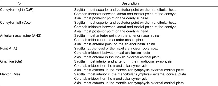
The raw data from the CBCT scan were reconstructed, coded, and converted into a Dicom3 file format using XoranCat acquisition software (version 1.7.7, Xoran Technologies, Ann Arbor, Mich). The Dicom3 files then were imported to software (Mimics 8.13, Materialize Co, Leuven, Belgium) for assessment. A number of points and measurements were derived by the software to produce an individual analysis (Figure 1). A list and description of the points and measurements used in this analysis is provided in Tables 1 and 2.
Figure 1.

3D cephalogram.
Table 1.
3D Composite Norms: Description of Points
Table 2.
3D Composite Norms: Description of Angular and Linear Measurements
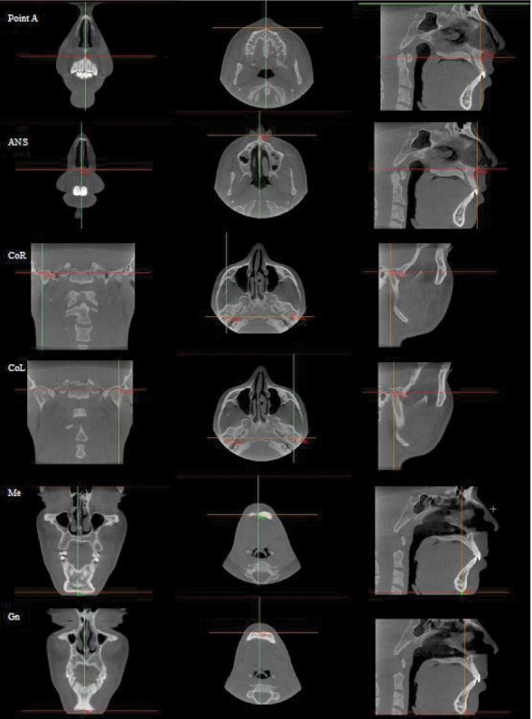
The points (point A, ANS, CoR, CoL, Me, Gn) were marked using the 2D multiplanar reconstruction (MPR) images (axial, sagittal, and coronal slices) according to their descriptions (Figure 2). It is important that the points satisfy all of the description requirements in all three planes of space at the same time. The measurements were calculated by computer and displayed in a separate window.
Figure 2.

Point location on multiplanar reconstruction images.
Derived Groups
The magnification group
The measurements obtained from the lateral cephalograms were reduced by 10%, the known magnification factor of the lateral head film.
The algorithm group
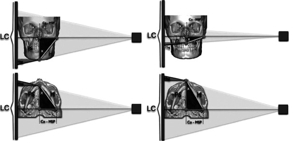
The measurements obtained from the lateral cephalograms were corrected using an algorithm based on trigonometry principles. This correction was possible because two of the points chosen for this analysis—condylion right and condylion left (CoR and CoL)—were located at the central focus of the X-ray beam, where the effects of magnification are negligible; the other points were located at the midsagittal plane where the magnification was determined easily. The magnification, however, varied depending on the plane in which a given structure was located.1,14 Based on these premises, a right triangle (Figure 3) was constructed with sides described as follows:
Figure 3.

Lateral head film image construction diagram.
The hypotenuse (H) represented the 3D measurement of either mandibular length (Co-Gn) or midface length (Co-point A).
The condylion to midsagittal plane side (Co-MSP) represented the distance between the condylion and the midsagittal plane.
The projection side (PS) represented the projection of the 3D measurement on the midsagittal plane. The PS was equal to the measurement from a lateral cephalogram, reduced by the magnification (Figure 3).
The hypotenuse could be calculated if both the projected side and the condylion to the midsagittal plane distance were known, using the Pythagorean theorem (Figure 3).
If the condylion to the midsagittal plane distance was not known, the hypotenuse could be calculated easily by dividing the projected side by the cosine of the angle “X” between the hypotenuse and the projected side (Figure 3). Because we do not have access to the missing link (condylion to midsagittal plane distance or the “X” angle from the original standard sample), we use the CBCT data to derive individualized correction factors that are applicable for that particular subject or sample.
By simple algebraic calculations, it was possible to translate the measurements from a lateral cephalogram to those obtained from 3D CBCT image and vice-versa.
 |
Measurements on the midsagittal plane were calculated simply by reducing the magnification because the cosine of zero was equal to one.
Data Analysis
All data were exported to statistical software (SPSS, version 14, Cary, NC) for analysis. The data consisted of four groups, each containing three measurements (midface length, mandibular length, and LAFH) of the same 13 individuals:
the cephalometric measurement group: measurements obtained directly from the cephalogram
the magnification correction group: measurements from the lateral cephalogram reduced by the magnification factor of the lateral head film
the algorithm correction group: measurements from the lateral cephalogram corrected for magnification and distortion using the algorithm, and
the CBCT measurement group: measurements directly from the CBCT scan.
The mean values of the right and left midface and mandibular lengths on the CBCT of each patient were used to match the other groups that used cephalometric measurements and therefore were derived from the mean measurements of those bilateral anatomical structures on the lateral radiograph.
Method Error
The principal investigator repeated all measurements within a 1-month interval. The intraobserver variability was 0.5 mm (±0.2 mm) for the cephalometric measurements and 0.2 mm (±0.1 mm) for the CBCT measurements according to Dahlberg's formula: √∑D2/2N.15
Statistical Analysis
The mean values of the four groups tested for the three measurements were compared using a repeated measures analysis of variance (R-ANOVA). Post-hoc comparisons of means were carried out using the Bonferroni correction for multiple comparisons.
RESULTS
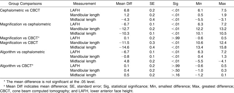
All results reported are based on the post-hoc pair-wise comparisons of means (Table 3) from the repeated measures ANOVA with a .05 level of significance.
Table 3.
Mean Values and Standard Deviation for Each Measurement on Each of the Four Groupsa
The three measurements from the cephalometric measurement group and the CBCT measurement group were significantly different from each other. These differences were even greater when the cephalometric measurement group was corrected for the magnification (magnification correction group), except for the LAFH measurement that displayed an extremely small mean difference (0.1 mm). There was a marked mean difference reduction on all three measurements when the algorithm was applied; there was no statistical difference between the algorithm correction group and the CBCT measurement group.
DISCUSSION
Since the time of Broadbent,1 many authors have proposed ways to combine the lateral, frontal, and submental vertex radiographs to obtain a 3D assessment of the patient.16 Kusnoto et al.17 used computer software and algorithms based on the three types of radiographs using a special facebow to position the patient accurately, while Nakasima et al.18 combined photographs, study models, and radiographs to produce a 3D model of the patient.
Unfortunately, these complex algorithms rely on combinations that are not available from most existing growth studies—studies that are comprised for the most part of lateral head films. The proposed algorithm in this paper relies on the patients' 3D data to derive normative values from known 2D lateral cephalometric norms.
Taking 3D measurements directly from the 3D examinations such as CBCT or even 3D photographs allows us to quantify accurately the right and left sides of the patient separately. A diagnosis then can be reached by comparing the deviation of those measurements from “normal values.” Unfortunately, the exact nature of such “normal values” for 3D measurements remains undefined. The algorithm proposed herein can be used to correct the existing 2D cephalometric norms (on and off the midsagittal plane) into more accurate 3D norms.
Direct 3D measurements have marked advantages over other methods proposed recently in the literature, such as using 3D scans to synthesize a 2D image similar to that produced by radiographs19,20; performing cephalometric analysis on this image still has the characteristics and limitations of a traditional cephalometric examination.
It is recommended to identify landmarks in the MPR images (ie, the three simultaneous views of a landmark location available in most 3D software analysis programs) and not on the rendered or segmented 3D volume (ie, the 3D virtual model that can be rotated in all three planes).9,21 Using the MPR slices improved the accuracy of landmark selection because there is increased variability when the 3D volume is used for landmark localization, depending on the segmentation threshold (ie, the levels of Hounsfield units) selected to construct the 3D volume.22
Periago et al.23 found mean differences of 1.2% when comparing 3D measurements from 3D rendered volumes to direct measurements on a skull, a difference the authors said was clinically irrelevant. Disler et al.4 reported that segmented 3D volumes derived from CBCT images demonstrated less than 1% relative error when compared to the gold standard of physical measures directly from skulls. Still, Ludlow et al.10 reported even better results (0.6% error) were accomplished when axial MPR images where used.
According to de Oliveira et al.,8 the location of each point must be defined precisely in all three planes of space using the MPR images for these measurements to be reproducible accurately. More studies, however, should investigate the interobserver reliability of CBCT measurements within a large group of orthodontists.
All measurements (LAFH, midface length, and mandibular length) that are derived from a conventional lateral cephalogram are significantly different from the 3D measurements on a CBCT (mean difference of 6.8 mm; 1.2 mm and −4.3 mm, respectively; Table 4). These differences constitute an error when using 2D cephalometric norms for 3D measurements. These results were also found in our previous ex vivo studies.
Table 4.
Pair-Wise Group Comparisons for Each Measurement, Using Repeated Measures ANOVA (P > .05) with Bonferroni Correctiona
The mean difference between mandibular length measured on a conventional radiograph and the same measurement on a CBCT is relatively small (1.2 mm); however, this difference still is statistically and clinically significant. This difference probably is due to the magnification increase that partially compensates for the reduction that occurs when the mandible is projected on a 2D film.24
Correcting only for the image magnification and not for the image distortion does not translate the 2D linear measurements taken from a conventional lateral head radiograph to a 3D linear measurement taken from a CBCT scan (mean difference of −11.5 mm and −14.6 mm, respectively; P < .01; Table 4), unless the structures from which the distance will be measured are located in the midsagittal plane, as for example LAFH (mean difference of 0.1 mm; P > .99; Table 4).
Patients rather than skulls were used to reproduce and validate the clinical applicability of the algorithm and avoid problems with loss of temporomandibular joint soft tissue and occlusal instability. Using cadaver heads or phantoms with nonmetallic fiducial markers could reduce problems with head orientation on the cephalostat; in the present study, however, care was taken to obtain high-quality lateral head films. By doing so, we increased the external validity and clinical application of the proposed algorithm because the algorithm was tested in conditions similar to those found in clinical practice.
The three measurements used in this study are part of an analysis first introduced by McNamara and Brudon25 in 1984 and were chosen because they represent measurements both on and off the midsagittal plane for which floating normal values based on proportions rather than fixed standard values are available: the so-called “composite norms.”
The use of proportions, geometric relationships, and floating norms is an important concept to bear in mind when deciding which measurements to make and what we want to achieve with this new 3D technology.
It may be possible to apply this concept (ie, algorithm) to other existing cephalometric longitudinal growth studies in order to derive control groups for future research or validated 3D norms for different analysis without exposing new untreated subjects to radiation.
CONCLUSIONS
Measurements taken on a conventional lateral cephalogram are significantly different from those taken from a CBCT scan of the same person.
Measurements taken on a conventional lateral cephalogram and then reduced by the magnification on the radiograph are significantly different from those taken with a CBCT scan, unless the structures from which the distance will be measured are located on the midsagittal plane.
The measurements of LAFH, midface length, and mandibular length can be corrected accurately by using the algorithm proposed in this study.
By applying this algorithm to other existing cephalometric longitudinal growth studies, normative values for 3D measurements could be derived without exposing new untreated subjects to radiation.
REFERENCES
- 1.Broadbent B. H. A new x-ray technique and its application to orthodontia. Angle Orthod. 1931;1:45–66. [Google Scholar]
- 2.Baumrind S, Frantz R. C. The reliability of head film measurements. 1. Landmark identification. Am J Orthod. 1971;60:111–127. doi: 10.1016/0002-9416(71)90028-5. [DOI] [PubMed] [Google Scholar]
- 3.Adams G. L, Gansky S. A, Miller A. J, Harrell W. E, Jr, Hatcher D. C. Comparison between traditional 2-dimensional cephalometry and a 3-dimensional approach on human dry skulls. Am J Orthod Dentofacial Orthop. 2004;126:397–409. doi: 10.1016/j.ajodo.2004.03.023. [DOI] [PubMed] [Google Scholar]
- 4.Disler D. G, Marr D. S, Rosenthal D. I. Accuracy of volume measurements of computed tomography and magnetic resonance imaging phantoms by three-dimensional reconstruction and preliminary clinical application. Invest Radiol. 1994;29:739–745. doi: 10.1097/00004424-199408000-00002. [DOI] [PubMed] [Google Scholar]
- 5.Hilgers M. L, Scarfe W. C, Scheetz J. P, Farman A. G. Accuracy of linear temporomandibular joint measurements with cone beam computed tomography and digital cephalometric radiography. Am J Orthod Dentofacial Orthop. 2005;128:803–811. doi: 10.1016/j.ajodo.2005.08.034. [DOI] [PubMed] [Google Scholar]
- 6.Swennen G. R, Schutyser F. Three-dimensional cephalometry: spiral multi-slice vs cone-beam computed tomography. Am J Orthod Dentofacial Orthop. 2006;130:410–416. doi: 10.1016/j.ajodo.2005.11.035. [DOI] [PubMed] [Google Scholar]
- 7.Siewerdsen J. H, Jaffray D. A. Cone-beam computed tomography with a flat-panel imager: effects of image lag. Med Phys. 1999;26:2635–2647. doi: 10.1118/1.598803. [DOI] [PubMed] [Google Scholar]
- 8.de Oliveira A. E, Cevidanes L. H, Phillips C, Motta A, Burke B, Tyndall D. Observer reliability of three-dimensional cephalometric landmark identification on cone-beam computerized tomography. Oral Surg Oral Med Oral Pathol Oral Radiol Endod. 2009;107:256–265. doi: 10.1016/j.tripleo.2008.05.039. [DOI] [PMC free article] [PubMed] [Google Scholar]
- 9.Ludlow J. B, Gubler M, Cevidanes L, Mol A. Precision of cephalometric landmark identification: cone-beam computed tomography vs conventional cephalometric views. Am J Orthod Dentofacial Orthop. 2009;136:312.e311–310; discussion 312–313. doi: 10.1016/j.ajodo.2008.12.018. [DOI] [PMC free article] [PubMed] [Google Scholar]
- 10.Ludlow J. B, Laster W. S, See M, Bailey L. J, Hershey H. G. Accuracy of measurements of mandibular anatomy in cone beam computed tomography images. Oral Surg Oral Med Oral Pathol Oral Radiol Endod. 2007;103:534–542. doi: 10.1016/j.tripleo.2006.04.008. [DOI] [PMC free article] [PubMed] [Google Scholar]
- 11.Cevidanes L. H, Bailey L. J, Tucker S. F, Styner M. A, Mol A, Phillips C. L, Proffit W. R, Turvey T. Three-dimensional cone-beam computed tomography for assessment of mandibular changes after orthognathic surgery. Am J Orthod Dentofacial Orthop. 2007;131:44–50. doi: 10.1016/j.ajodo.2005.03.029. [DOI] [PMC free article] [PubMed] [Google Scholar]
- 12.Stratemann S. A, Huang J. C, Maki K, Miller A. J, Hatcher D. C. Comparison of cone beam computed tomography imaging with physical measures. Dentomaxillofac Radiol. 2008;37:80–93. doi: 10.1259/dmfr/31349994. [DOI] [PubMed] [Google Scholar]
- 13.Kwon T. G, Park H. S, Ryoo H. M, Lee S. H. A comparison of craniofacial morphology in patients with and without facial asymmetry—a three-dimensional analysis with computed tomography. Int J Oral Maxillofac Surg. 2006;35:43–48. doi: 10.1016/j.ijom.2005.04.006. [DOI] [PubMed] [Google Scholar]
- 14.Ahlqvist J, Eliasson S, Welander U. The effect of projection errors on cephalometric length measurements. Eur J Orthod. 1986;8:141–148. doi: 10.1093/ejo/8.3.141. [DOI] [PubMed] [Google Scholar]
- 15.Houston W. J. The analysis of errors in orthodontic measurements. Am J Orthod. 1983;83:382–390. doi: 10.1016/0002-9416(83)90322-6. [DOI] [PubMed] [Google Scholar]
- 16.Rousset M. M, Simonek F, Dubus J. P. A method for correction of radiographic errors in serial three-dimensional cephalometry. Dentomaxillofac Radiol. 2003;32:50–59. doi: 10.1259/dmfr/51868734. [DOI] [PubMed] [Google Scholar]
- 17.Kusnoto B, Evans C. A, BeGole E. A, de Rijk W. Assessment of 3-dimensional computer-generated cephalometric measurements. Am J Orthod Dentofacial Orthop. 1999;116:390–399. doi: 10.1016/s0889-5406(99)70223-4. [DOI] [PubMed] [Google Scholar]
- 18.Nakasima A, Terajima M, Mori N, Hoshino Y, Tokumori K, Aoki Y, Hashimoto S. Three-dimensional computer-generated head model reconstructed from cephalograms, facial photographs, and dental cast models. Am J Orthod Dentofacial Orthop. 2005;127:282–292. doi: 10.1016/j.ajodo.2003.11.030. [DOI] [PubMed] [Google Scholar]
- 19.Farman A. G, Scarfe W. C. Development of imaging selection criteria and procedures should precede cephalometric assessment with cone-beam computed tomography. Am J Orthod Dentofacial Orthop. 2006;130:257–265. doi: 10.1016/j.ajodo.2005.10.021. [DOI] [PubMed] [Google Scholar]
- 20.Cattaneo P. M, Bloch C. B, Calmar D, Hjortshoj M, Melsen B. Comparison between conventional and cone-beam computed tomography-generated cephalograms. Am J Orthod Dentofacial Orthop. 2008;134:798–802. doi: 10.1016/j.ajodo.2008.07.008. [DOI] [PubMed] [Google Scholar]
- 21.Grauer D, Cevidanes L. S, Proffit W. R. Working with DICOM craniofacial images. Am J Orthod Dentofacial Orthop. 2009;136:460–470. doi: 10.1016/j.ajodo.2009.04.016. [DOI] [PMC free article] [PubMed] [Google Scholar]
- 22.Halazonetis D. J. From 2-dimensional cephalograms to 3-dimensional computed tomography scans. Am J Orthod Dentofacial Orthop. 2005;127:627–637. doi: 10.1016/j.ajodo.2005.01.004. [DOI] [PubMed] [Google Scholar]
- 23.Periago D. R, Scarfe W. C, Moshiri M, Scheetz J. P, Silveira A. M, Farman A. G. Linear accuracy and reliability of cone beam CT derived 3-dimensional images constructed using an orthodontic volumetric rendering program. Angle Orthod. 2008;78:387–395. doi: 10.2319/122106-52.1. [DOI] [PubMed] [Google Scholar]
- 24.Chidiac J. J, Shofer F. S, Al-Kutoub A, Laster L. L, Ghafari J. Comparison of CT scanograms and cephalometric radiographs in craniofacial imaging. Orthod Craniofac Res. 2002;5:104–113. doi: 10.1034/j.1600-0544.2002.01170.x. [DOI] [PubMed] [Google Scholar]
- 25.McNamara J. A, Jr, Brudon W. L. Orthodontics and Dentofacial Orthopedics. Ann Arbor, Mich: Needham Press; 2001. [Google Scholar]


