Abstract
Objective:
To compare cephalostat two-dimensional (2D) measurements to 3D computed tomography (CT) measurements in order to determine the compatibility of CT landmarks identification for orthodontic purposes.
Materials and Methods:
Ten human skulls were x-rayed in conventional lateral cephalogram and then scanned with spiral CT. Twenty-eight linear and angular cephalometric measurements were registered on the 2D lateral cephalogram and compared to the same measurement on the 3D CT scan. Significance of the results was determined by t-test for paired differences (P < .05).
Results:
No difference was found between 2D and 3D images for linear or ratio measurements. As for the angular cephalometric measurements, only the sella turcica dependent measurements, showed significant difference between 2D and 3D.
Conclusions:
The compatibility of using most of the common orthodontic examined cephalometric measurements on 3D volume rendered image was proven except for the angular measurements that included sella anatomic landmark.
Keywords: CT, Cephalometric, Analysis
INTRODUCTION
For more than seven decades cephalometry has been one of the main diagnostic tools available to the orthodontist. Cephalometric norms were published by prominent clinicians and researchers, and are used for diagnosis, treatment progress, posttreatment evaluation, and research.1–6 Since the early days of cephalometry, many attempts were published to allow three-dimensional (3D) imaging and analysis. The first cephalostat, developed by Broadbent, made possible lateral and frontal roentgenograms of the patient's head, with the patient's head held by a head holder.7 Broadbent's analysis was meant to be 3D, stereoscopic, and to give a diagnosis of facial relations in three dimensions. Other, more recent 3D reconstructions of 2D images are known in the orthodontic literature.8 The attempt to develop 3D analysis and diagnosis is more interesting today, with the widespread use of multislice computed tomography (MSCT) imaging with its multiplanar capabilities.
With the advancement of helical computer tomography (CT) and 3D techniques, the traditional imaging methods should be reevaluated. We witness today new voices in the orthodontic literature that claim that the 2D method of diagnosis is obsolete, and that in the future, cephalometry will be primarily, if not solely, 3D based.9,10 The invention of new imaging techniques allows us improved 3D imaging at lower costs and relatively low radiation exposure.10–17
Periago et al.18 compared cone beam CT (CBCT) 3D measurements to direct measurements on human skull and concluded that these reconstructed imaging reflect the true linear distances between anatomic landmarks of the skull. This observation supports the idea that CT should be considered the gold standard for cephalometric measurements. Other researchers proved the accuracy and precision of 3D landmark identification at various exposure protocols.19–21
The purpose of this study is to compare cephalostat 2D cephalometric measurements to 3D CT measurements in order to determine the compatibility of CT for common orthodontic cephalometric analyses.
MATERIALS AND METHODS
Ten human dry skulls with stable and reproducible occlusal relationship were used for this study. No demographic data were available; the skulls were not identified by age, sex, or ethnicity. Each skull was scanned with conventional lateral cephalogram and CT. Cephalograms were performed with a cephalostat machine which has 9% magnification (Cranex, Soredex, Tuusula, Finland).
CT was performed with a 16-slice helical scanner (GE-LightSpeed, GE Medical Systems, Milwaukee, Wis). Each skull was placed on the center of a dedicated head holder of the CT machine with the Frankfort horizontal plane parallel to the floor. The scanner light beam was used to reassure symmetry of the skull position in the sagittal and axial planes. The scan was performed in a caudal-cranial direction from below the mandible to above the cranial convexity using the following parameters: 80 kVp, automated mA, 0.625-mm slice thickness reconstructed in 2.5 mm, 0.9 pitch, small FOV, and a 512 × 512 matrix. CT data were transferred to an independent workstation (Advantage Windows 4.2, GE, Milwaukee, Wis) for postprocessing. Radiation exposure was approximately 1 mSv.
For the lateral cephalogram, the skull was stabilized by two ear rods in the external auditory meatuses and positioned with the Frankfort horizontal plane parallel to the floor, the sagittal plane perpendicular to the x-ray beam, and the left side closest to the detector. For CT imaging, the skull was stabilized with a head holder in the machine. The Frankfort horizontal was set as parallel to the horizon with the software tools before analysis. Twenty-eight linear and angular measurements were registered on 2D lateral cephalogram and compared to the same measurement registered on the 3D CT scan.
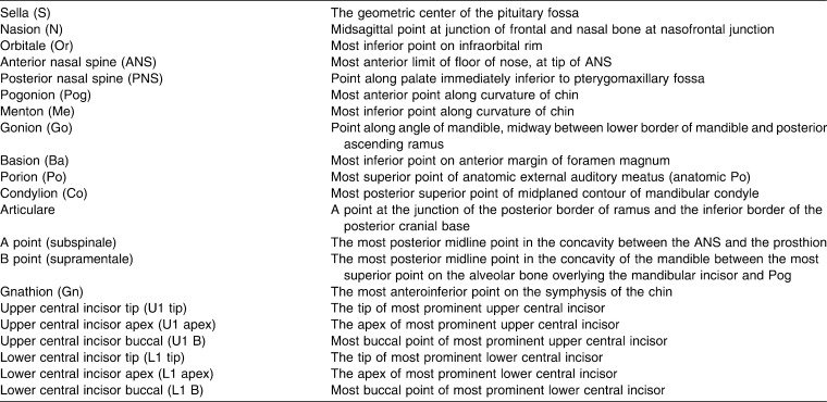
Each conventional cephalogram was traced manually on 0.003-inch thick matte acetate cephalometric tracing paper (GAC International, Bohemia, NY) with a 0.5-mm diameter (2B) mechanical lead pencil. Cephalometric landmarks were recognized as described in Table 1. Commonly used cephalometric linear distances and angular measurements were measured and/or calculated.
Table 1.
Description of the Cephalometric Landmarks
The 3D measurements were measured by distance and angular tools of commercial software. Each anatomic measurement was identified as a 3D point with the software. The software enables simultaneously recognizing the same spatial point in sagittal, coronal, and axial planes, which are represented in three separate windows (Figure 1). A fourth window allows the recognition of the anatomic point on a volume rendered (VR) window, which is a 3D image of the skull. The measurements were made by the same trained practitioner, at two separate times (4-week interval), in a darkened room with a black surround. Within 2D conventional lateral cephalogram analysis and 3D computed tomography analysis, the repeated measurements were compared with t-test for paired differences.
Figure 1.
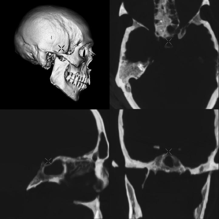
3D anatomic landmark recognition. The figure represents 3D localization of the sella turcica anatomic landmark by simultaneous localization on separate spatial planes (sagittal, coronal, and axial).
The null hypothesis assumed that the repeated measurements are in a same distribution and have the same average. In case this assumption was rejected, the measurement was recorded again, but only when the difference was small. After repeatability of the measurements was proven, we compared the 2D measurements to the same measurements registered in 3D, also with t-test for paired differences (significance level was set as .05).
RESULTS
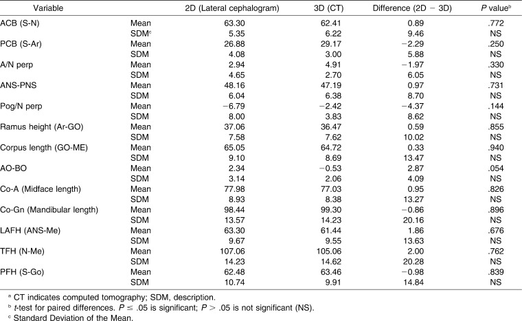
The results of comparisons of 2D measurements to 3D measurements are shown in Tables 2 through 4. There was no significant difference for linear measurements (Table 2) between 2D and 3D images. The only measurement that approached significant difference was AO-BO (Wits appraisal) with a P value of .054.
Table 2.
Comparison of 2D and 3D Linear Measurements (in mm)a
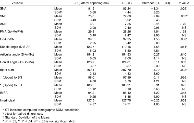
Table 3.
Comparison of 2D and 3D Angular Measurements (in degrees)a
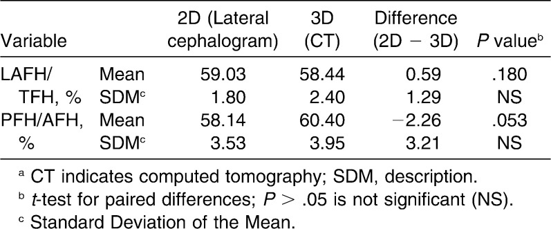
Table 4.
Comparison of 2D and 3D Ratio Measurementsa
As for angular cephalometric measurements, there was no difference between conventional lateral cephalogram analysis and 3D analysis for most of the measurements, excluding the S (sella turcica) dependent measurements such as SNA, SNB, Go-Gn/SN, and saddle angle (N-S-Ar).
As for ratio measurements (LAFH/TFH, PFH/AFH), there was no difference between 2D and 3D images (Table 4).
DISCUSSION
This is a pioneer study, designed to estimate the feasibility of measuring common cephalometric measurements on a 3D image. The anatomic landmarks which were used on 2D cephalogram are better visualized in 3D images. The software which was used for this study enables pinpoint location of most of the anatomic landmarks. The same landmark is pointed in three anatomic planes and the 3D image on four different screens (Figure 1). The cross-shaped cursor automatically indicates the exact location in every spatial plane (sagittal, coronal, horizontal, and 3D-VR). CT measurements can be performed very precisely in a digital mode.
In a conventional 2D image, only a shadow of the bone can be appreciated and measurements are performed manually in a rather primitive fashion. Even after subtracting the 9% magnification of the lines measured on the lateral 2D cephalogram image, there were no differences between the 2D and the 3D images. The only measurement that approached significant difference was AO-BO (Wits appraisal), P = .054. But the average difference between the 2D AO-BO and the 3D AO-BO was about 0.5 mm, which is obviously not clinically significant.
Ratio measurements (LAFH/TFH, PFH/AFH) were similar between 2D and 3D analysis. Obviously, the magnification of the images on the 2D is irrelevant when calculating the ratio of two lines from the same image.
The results obtained in this study suggest that orthodontists can use linear and ratio measurements determined in 3D CT similar to the way used in conventional 2D cephalogram analyses.
Most of the measured angular measurements did not show any statistical difference between 2D cephalogram and 3D imaging. The angles that differed were those which included the sella turcica anatomic landmark as one of the angle line points. The sella turcica anatomic landmark was identified differently on lateral cephalogram and in the 3D analysis. The 3D location of the mid-sella point is more precise with CT, since the exact location could be estimated automatically on the workstation in three planes including the laterolateral plane. This process is not possible with 2D imaging.
Previous research attempted to examine the feasibility of using 2D cephalometric images rendered from 3D scan.22,23 Our study examined the possibility of using conventional linear and angular cephalometric measurement directly on a CT volume rendered image. In contrast to the study by Adams et al.,24 which compared 2D and 3D linear measurements to physical measurement of the dry skull and concluded that the conventional 2D system often renders both inaccurate and imprecise results, our results indicate that the differences are small.
CT 3D images for orthodontic purposes have several important advantages over conventional 2D images. CT provides a volume rendered image of the skull that can be evaluated in any plan, enabling accurate appreciation of the real shape of the skull, jaws, and facial bones and allowing precise measurements of the relationships between them. This advantage of the 3D images has a paramount importance in cases of craniofacial or orofacial anomalies.
CBCT is associated with less radiation exposure to the patient and therefore is preferred to MSCT for dental purposes. In CBCT the cone-shaped x-ray beam enables acquisition of a long segment within one rotation of the x-ray source, while in MSCT multiple rotations of the x-ray source in the z axis are needed to cover the full length of the skull. However, since only the bones should be demonstrated for orthodontic measurements, and since high resolution is not an issue in this case, the radiation doses given in such a study may be further reduced by half or more even in a conventional MSCT scanner. This can be achieved by lowering of the kVp and mA to a minimum possible.
Our study tried to convert traditional 2D based measurements to 3D images. Because 3D CT has the potential to be more informative and precise than the 2D measurement, the new, simple, and dedicated CT measurement method should be created to increase the diagnostic acumen of this technique. Our preliminary results are encouraging, but it is obvious that application of 2D analysis to 3D images requires more research in the future. Different parameters for 3D measurement should be established, which can create a more accurate, easy, and elegant method for cephalometric evaluation.
There are several limitations for our study. First our sample is relatively small and included only 10 skulls. In addition, all measurements were performed by the same operator with intraobserver but not interobserver method of measurement. The minimal radiation dose possible with MSCT for this study was not evaluated. Further studies on a larger sample group with reduced radiation dose are needed.
CONCLUSIONS
We can use most of the examined cephalometric measurements calculated previously from 2D images, on 3D volume rendered image, excluding angular measurements that include the sella anatomic landmark as one of the angle line points.
REFERENCES
- 1.Downs W. B. Variations in facial relationship—their significance in treatment and prognosis. Am J Orthod. 1948;34:812–840. doi: 10.1016/0002-9416(48)90015-3. [DOI] [PubMed] [Google Scholar]
- 2.Downs W. B. The role of cephalometrics in orthodontic case analysis and diagnosis. Am J Orthod. 1952;38:162–182. [Google Scholar]
- 3.Downs W. B. Analysis of dentofacial profile. Angle Orthod. 1956;26:191–212. [Google Scholar]
- 4.Steiner C. C. The use of cephalometrics as an aid to planning and assessing orthodontic treatment. Am J Orthod. 1960;46:721–735. [Google Scholar]
- 5.Ricketts R. M. Perspectives in the clinical application of cephalometrics. The first fifty years. Angle Orthod. 1981;51:115–150. doi: 10.1043/0003-3219(1981)051<0115:PITCAO>2.0.CO;2. [DOI] [PubMed] [Google Scholar]
- 6.McNamara J. A., Jr A method of cephalometric evaluation. Am J Orthod. 1984;86:449–468. doi: 10.1016/s0002-9416(84)90352-x. [DOI] [PubMed] [Google Scholar]
- 7.Broadbent B. H. A new X-ray technique and its application to orthodontia. Angle Orthod. 1931;1:45–66. [Google Scholar]
- 8.Baumrind S, Carlson S, Beers A, Curry S, Norris N, Boyd R. L. Using three-dimensional imaging to assess treatment outcomes in orthodontics: a progress report from the University of the Pacific. Orthod Craniofac Res. 2003;6(suppl):132–142. doi: 10.1034/j.1600-0544.2003.246.x. [DOI] [PubMed] [Google Scholar]
- 9.Halazonetis D. J. From 2-dimensional cephalograms to 3-dimensional computed tomography scans. Am J Orthod Dentofacial Orthop. 2005;127:627–637. doi: 10.1016/j.ajodo.2005.01.004. [DOI] [PubMed] [Google Scholar]
- 10.Swennen G. R. J, Schutyser F, Hausamen J. E. Three Dimensional Cephalometry – A Color Atlas and Manual. Berlin, Germany: Springer; 2005. [Google Scholar]
- 11.Mah J, Danforth R. A, Bumann A, Hatcher D. Radiation absorbed in maxillofacial imaging with a new dental computed tomography device. Oral Surg Oral Med Oral Pathol Oral Radiol Endod. 2003;96:508–513. doi: 10.1016/s1079-2104(03)00350-0. [DOI] [PubMed] [Google Scholar]
- 12.Mah J, Hatcher D. Current status and future needs in craniofacial imaging. Orthod Craniofac Res. 2003;6(suppl):10–16. doi: 10.1034/j.1600-0544.2003.230.x. [DOI] [PubMed] [Google Scholar]
- 13.Maki K, Inou N, Takanishi A, Miller A. J. Computer-assisted simulations in orthodontic diagnosis and the application of a new cone beam X-ray computed tomography. Orthod Craniofacial Res. 2003;6(suppl):95–101. doi: 10.1034/j.1600-0544.2003.241.x. [DOI] [PubMed] [Google Scholar]
- 14.Hashimoto K, Arai Y, Iwai K, Araki M, Kawashima S, Terakado M. A comparison of a new limited cone beam computed tomography machine for dental use with multidetector row helical CT machine. Oral Surg Oral Med Oral Pathol Oral Radiol Endod. 2003;95:371–377. doi: 10.1067/moe.2003.120. [DOI] [PubMed] [Google Scholar]
- 15.Kau C. H, Richmond S, Palomo J. M, Hans M. G. Current products and practice three dimensional cone beam computerized tomography in orthodontics. J Orthod. 2005;32:282–293. doi: 10.1179/146531205225021285. [DOI] [PubMed] [Google Scholar]
- 16.Sukovic P. Cone beam computed tomography in craniofacial imaging. Orthod Craniofac Res. 2003;6(suppl):31–36. doi: 10.1034/j.1600-0544.2003.259.x. [DOI] [PubMed] [Google Scholar]
- 17.Yamamoto K, Uneo K, Seo K, Shinohara D. Development of dento-maxillofacial cone beam X-ray computed tomography system. Orthod Craniofac Res. 2003;6(suppl):160–162. doi: 10.1034/j.1600-0544.2003.249.x. [DOI] [PubMed] [Google Scholar]
- 18.Periago D. R, Scarfe W. C, Moshiri M, Scheetz J. P, Silveira A. M, Farman A. G. Linear accuracy and reliability of cone beam CT derived 3-dimensional images constructed using an orthodontic volumetric rendering program. Angle Orthod. 2008;78:387–395. doi: 10.2319/122106-52.1. [DOI] [PubMed] [Google Scholar]
- 19.Olszewski R, Reychler H, Cosnard G, Denis J. M, Vynckier S, Zech F. Accuracy of three-dimensional (3D) craniofacial cephalometric landmarks on a low-dose 3D computed tomography. Dentomaxillofac Radiol. 2008;37:261–267. doi: 10.1259/dmfr/33343444. [DOI] [PubMed] [Google Scholar]
- 20.Connor S. E, Arscott T, Berry J, Greene L, O'Gorman R. Precision and accuracy of low-dose CT protocols in the evaluation of skull landmarks. Dentomaxillofac Radiol. 2007;36:270–276. doi: 10.1259/dmfr/90016954. [DOI] [PubMed] [Google Scholar]
- 21.Cavalcanti M. G, Rocha S. S, Vannier M. W. Craniofacial measurements based on 3D-CT volume rendering: implications for clinical applications. Dentomaxillofac Radiol. 2004;33:170–176. doi: 10.1259/dmfr/13603271. [DOI] [PubMed] [Google Scholar]
- 22.Chidiac J. J, Shofer F. S, Al-Kutombi, Laster L. L, Ghafari J. Comparison of CT scanograms and cephalometric radiographs in craniofacial imaging. Orthod Craniofac Res. 2002;5:104–113. doi: 10.1034/j.1600-0544.2002.01170.x. [DOI] [PubMed] [Google Scholar]
- 23.Moshiri M, Scarfe W. C, Hilgers M. L, Scheetz J. P, Silveira A. M, Farmen A. G. Accuracy of linear measurements from imaging plate and lateral cephalometric images derived from cone-beam computed tomography. Am J Orthod Dentofacial Orthop. 2007;132:550–560. doi: 10.1016/j.ajodo.2006.09.046. [DOI] [PubMed] [Google Scholar]
- 24.Adams G. L, Gansky S. A, Miller A. J, Harrell W. E, Jr, Hatcher D. C. Comparison between traditional 2-dimensional cephalometry and a 3-dimensional approach on human dry skulls. Am J Orthod Dentofacial Orthop. 2004;126:397–409. doi: 10.1016/j.ajodo.2004.03.023. [DOI] [PubMed] [Google Scholar]
- 25.Olszewski R, Zech F, Cosnard G, Nicolas V, Macq B, Reychler H. Three-dimensional computed tomography cephalometric craniofacial analysis: experimental validation in vitro. Int J Oral Maxillofac Surg. 2007;36:828–833. doi: 10.1016/j.ijom.2007.05.022. [DOI] [PubMed] [Google Scholar]


