Abstract
Retinal surgery is known to be a complicated and challenging task for an ophthalmologist even for retina specialists. Image guided robot-assisted intervention is among the novel and promising solutions that may enhance human capabilities during microsurgery. In this paper, a novel method is proposed for 3D navigation of a microsurgical instrument based on the projection of a spotlight during robot-assisted retinal surgery. To test the feasibility and effectiveness of the proposed method, a vessel tracking task in a phantom with a Remote Center of Motion (RCM) constraint is performed by the Steady-Hand Eye Robot (SHER). The results are compared to manual tracking, cooperative control tracking with the SHER and spotlight-based automatic tracking with SHER. The reported results are that the spotlight-based automatic tracking with SHER can reach an average tracking error of 0.013 mm and keeping distance error of 0.1 mm from the desired range demonstrating a significant improvement compared to manual or cooperative control methods alone.
Keywords: Medical Robots and Systems, Robot-assisted Retinal Surgery, Autonomous Surgery
I. Introduction
RETINAL surgery is characterized by a complex workflow and delicate tissue manipulations (see Fig. 1), that require both critical manual dexterity and learned surgical skills. Retinal diseases affect more than 300 million patients worldwide resulting in severe visual impairment and a significant number of these required microsurgical invervention in order to preserve or restore vision [1]. Robot-assisted surgery (RAS) setups are envisioned as a potential solution for reducing the work intensity, improving the surgical outcomes, extending the service time of skilled microsurgeons. Autonomous systems in RAS have attracted growing research interests and it may someday assist the surgeons to operate the surgery with better quality and less time consumption [2], [3].
Fig. 1.
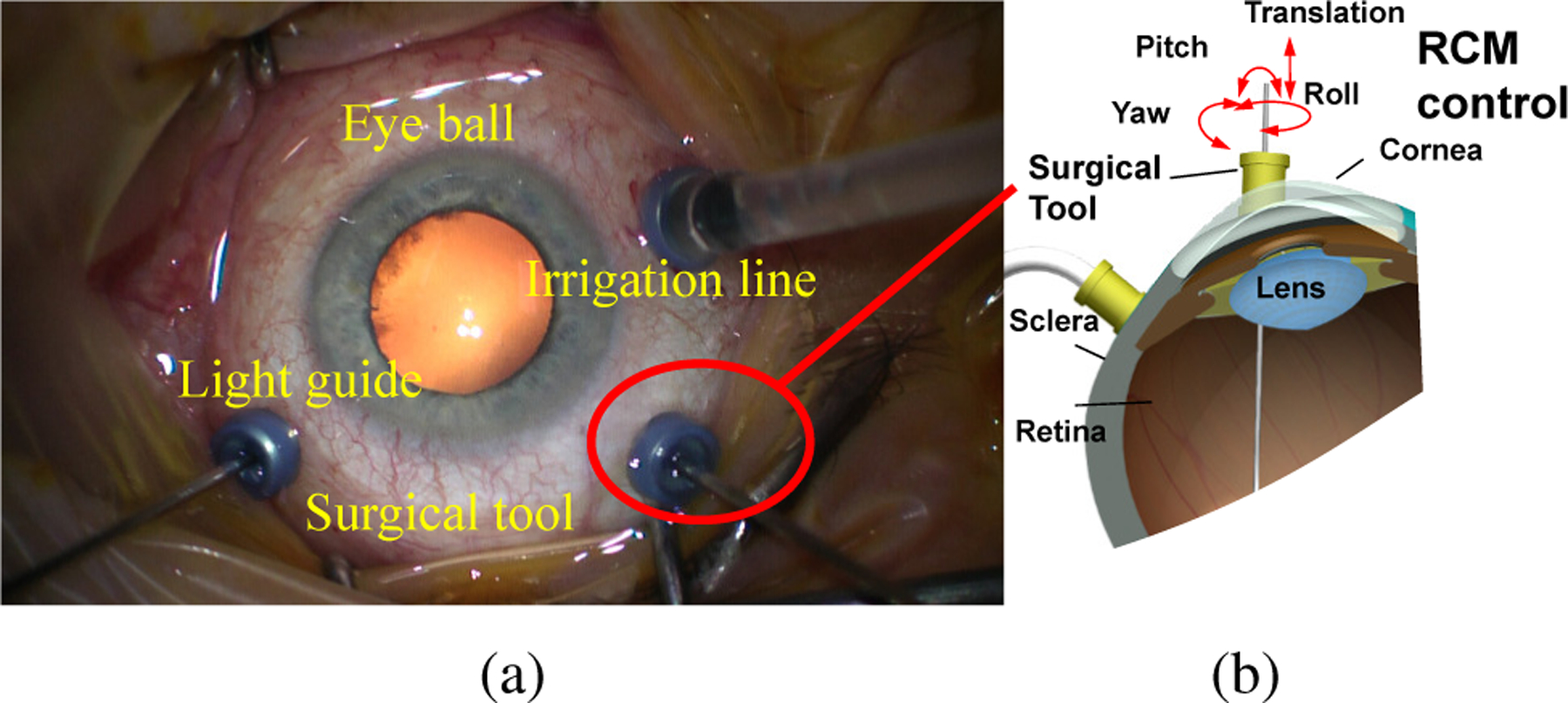
(a) Retinal surgery top view. (b) Remote Center Motion (RCM) in retinal surgery. The surgical tool movement is restricted by RCM control where the tool can only be pivoted around the incision point.
However, the introduction of autonomy into RAS is a challenging and long term research theme, which facing not only insufficient technique but also ethical issues. In ophthalmic surgery, the RAS has been researched to overcome surgeon’s physiological hand tremor and to achieve dexterous motion and precise RCM control. A lot of researchers have introduced robotic setups with high precision and different design mechanisms for eye surgeries [4]–[11]. The world first robotic eye surgery was performed in Oxford’s John Radcliffe Hospital using Robotic Retinal Dissection Device (R2D2) [12]. The autonomy in eye surgery is even more challenging due to its high precision and soft tissue interaction. The possibility of autonomy in retinal surgery relies on suitable sensing. The microscope images naively used during eye surgeries provide a suitable modality [13]. However, solely using microscope images cannot offer three-dimensional (3D) information. Optical Coherence Tomography(OCT) imaging modality with the depth resolution of 2 µm provides an ideal resolution for retinal surgery but with an image range limited to around 2 mm. OCT has been verified for the feasibility of needle navigation intraocular with robot by Zhou et al. [14] However, the contradiction of the image resolution and image range makes it less suitable for the guidance of instrument movements over a large range. A cuboid of 10 mm×10 mm×5 could be defined as the tool tip workspace based on the observation of typical retinal surgeries.
In order to guide the surgical tool intraocular in 3D with the expected workspace for autonomous task, a spotlight-based method is proposed in this paper to directly navigate instrument intraocular with active light projection. The paper is extended from our previous conference paper [15], with further contributions listed as follows,
Robot visual servoing with an RCM constraint is proposed for Steady-Hand Eye Robot (SHER) [16] using spotlight projection to navigate the instrument in 3D.
A vessel tracking task in a phantom with the RCM constraint is performed using three different operation modes which shows the potential benefits of the proposed method.
The rest of the article is organized as follows. Section III discusses the work related to autonomous retinal surgeries. Section III presents our method and its workflow. Section IV presents the evaluation of our research. Section V gives the conclusion of this paper.
II. Related work
Several autonomous retinal surgeries have been researched with different sensing modalities and control mechanisms.
The OCT is an ideal modality for precise control of the tool interaction with the eye tissue. Zhou et al. [14], [17] used the OCT images to automatically control the insertion depth for the subretinal injection. Gerber et al. [18] designed automated robotic cannulation for retinal vein occlusion with OCT navigation. The experiments were performed 30 times on the phantom veins with a diameter of around 20 microns. Yu et al. [19] proposed a B mode OCT probe for navigation the tools inside the eyeball using the parallel robot. The motion tracking error showed that the mean tracking error was 0.073 mm with a standard deviation of 0.052 mm, while the maximum error was 0.159mm. Song et al. [20] developed a robotic surgical tool with an integrated OCT probe to estimate single-dimensional distance between the surgical tool and eye tissue for membrane peeling purposes. Cheon et al. [21] developed a depth-locking handheld instrument that can automatically control the insertion depth with OCT B mode sensing. The integration of OCT probe into the instrument can simplify the acquisition setup avoiding the necessity of imaging through the cornea and crystalline lens. Weiss et al. [22] proposed a method combining several OCT B-scan and microscope images to estimate the 5 DoF needle pose for subretinal injection.
Kim et al. [13] automated the tool-navigation task by learning to predict relative goal position on the retinal surface from the current tool-tip position from a single microscope image. Based on the experiments performed with simulation and eye phantoms, they demonstrate that our framework can permit navigation to various points on the retina within 0.089 and 0.118 mm in XY error which is less than the human’s surgeon mean tremor at the tool-tip of 0.180 mm. In order to obtain more robust navigation intraocularly, a structure light-based method has also been introduced recently to navigate an instrument in 3D. Yang et al. estimated the retinal surface in the coordinate system of custom-built optical tracking system (ASAP) with structured-light reconstruction method, afterward the tip-to-surface distance was calculated in the coordinate system of ASAP with known the surface reconstruction [23], [24]. By way of comparison, this paper presented a method that mounts the beam onto the surgical tool. The spotlight fiber will project a pattern on the retinal surface. The project pattern in a monocular image is used to present the target place on the retina and this pattern can be also inferred from the tip to surface distance. Afterwards, the RCM constraint is proposed for navigation tools. The superiority of proactive spotlight is that the projection pattern is more robust against the illumination changes. Our method directly estimates the tool tip to retinal surface distance in real-time which is suitable for autonomous task execution. A vessel tracking task is given as an example to discuss the interesting observations among manual tracking, cooperative control tracking with SHER, and a spotlight-based automatic tracking method with SHER.
III. Method
The overall method is shown in Fig. 2. The mechanism of the spotlight is analyzed to build up the database required to reliably establish the relationship between tip-to-surface distance and projection pattern (Fig. 2 (a)). Then, a spotlight projection tracking method is implemented and a vision servoing control is formulated to achieve the autonomous motion control (Fig. 2 (b).). A vessel tracking task is then used to validate the proposed framework as shown in Fig. 2 (c).
Fig. 2.
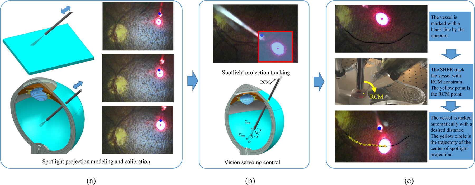
(a) The mechanism of the spotlight is analyzed to establish the relationship between tip-to-surface distance and projection pattern. This relationship can be obtained by knowing the characteristics of the spotlight or by calibration of the spotlight pattern with the known distance of the tip-to-surface. (b) A spotlight projection tracking method is thereby developed. Based on the tracking algorithm, a visual servoing control algorithm is formulated to achieve the autonomous motion control with RCM constraint. (c) The vessel tracking task is used to verify the proposed framework using the SHER robot. The effectiveness of the proposed method is validated in comparison to both manual tracking and cooperative control tracking with the SHER.
A. Tip to surface distance estimation
The spotlight is generated by the lens at the end-tip of beam to concentrate the light with the shape of a cone. The distance d between the spotlight end-tip and plane surface is calculated as follows,
| (1) |
where dp denotes the distance between the projection plane surface and spotlight end-tip. b and k are the constant parameters. e1 denotes the minor axis of ellipse.
The human eyeball is modeled as a sphere with a diameter of 25 mm [25]. To improve the accuracy of the distance estimation and simplify the calculation, the light spot on the projection surface is designed to be within around 2 mm, so that the projected area the significantly smaller than the eyeball diameter and can be treated as a small piece of plane, shown in Fig. 2 (a). Therefore, we have,
| (2) |
where ds is the distance between the spotlight tip and plane surface. SʹO is related to the value of e1, and r is the radius of the eyeball in the cross-section, shown in Fig. 3.
Fig. 3.
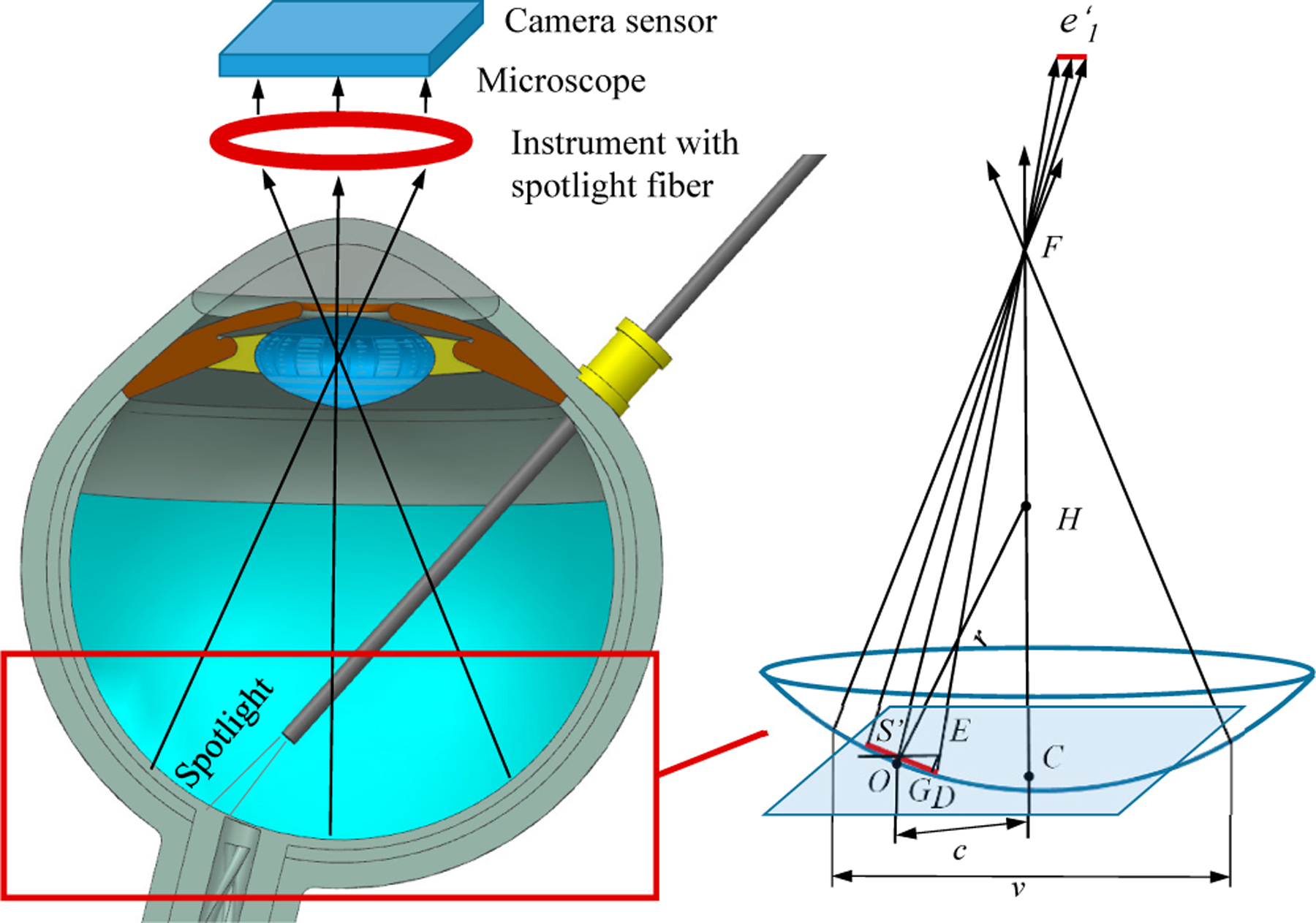
The projection of the spotlight on the eyeball surface and camera sensor in the microscope. F C denotes the center line of microscope. P is the plane with point Sʹ and parallel with camera sensor plane. E denotes the intersection point between F D and plane P. OD denotes the length of e1. EG is perpendicular with OD. H is the center of the sphere. c is the distance between point O and line F C. v is the view window size of microscope intraocular.
The microscope for retinal surgery is considered analogous to a pinhole camera model. The retina surface is assumed to be parallel or near parallel to the image plane. As the depth of field in intraocular microscopic imaging is quite shallow, focused images can be obtained only when the surface is located within a very narrow region perpendicular to the optical axis of the microscope [23], [26]. Therefore the detected ellipse minor axis in the microscope image has the proportional relation with the e1,
| (3) |
where δ is the ratio factor.
When the spotlight is projected on the eyeball surface, as shown in Fig. 3, then e1 can be calculated as follows,
| (4) |
where ∠ESʹD is the angle between SʹE and the tangent line of the circle. Due to the fact that the view window of microscope v is within around 10 mm during surgery, it can be inferred that DE < SʹE. The minimum of ∠SʹDE appears when the O locates at the edge of the view window of microscope. Since F is far away from Sʹ and SʹD is small, SʹF is treated equal to DF. cos∠SʹDE can be calculated,
| (5) |
Therefore, Eq. 4 can be rewritten as,
| (6) |
We can obtain following,
| (7) |
B. Image algorithm design
A straightforward method is proposed to track the projection pattern, shown as Fig. 4. First of all, the RGB image from camera is transferred to a gray image. To reduce unnecessary computation time, the gray image is cropped into a patch image with a width of 2p. The original patch location is initialized by the user with mouse clicking. The clicking mouse is a kind of confirmation by user for patch tracking. Since the spotlight projection pattern has a much brighter intensity than the background, the gray image patch is transferred into a binary image with fixed threshold. The noise in the binary image is suppressed by a median filter followed by a Gaussian filter for better tracking performance.
Fig. 4.
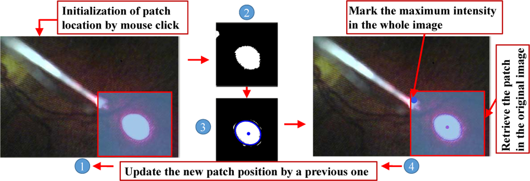
The framework of projection pattern tracking. ① denotes the original image. ② is the patch image. ③ is the patch image with the fitted ellipse. ④ denotes the retrieve image with patch.
The connected component labeling method is adopted to obtain the projection which is the maximum number of the connected components, meanwhile, this maximum number also needs to be more than Ts. This could help to further improve the tracking stability. The ellipse fitting is used to fit the edge of projection pattern in the binary patch image. The value of ellipse minor axis is set to lower than me. me is selected based on the size of projection pattern.
C. Robot Visual Servoing with RCM constraint
In the intended application of vessel tracking, the robot is first controlled in the cooperative mode for localizing the instrument inside the eye through the scleral incision (see Fig 5). Then the surgeon marks vessels location on the retina, the robot then controls the instrument to follow the vessel with RCM constraint and keeping a safe distance from the retinal surface.
Fig. 5.
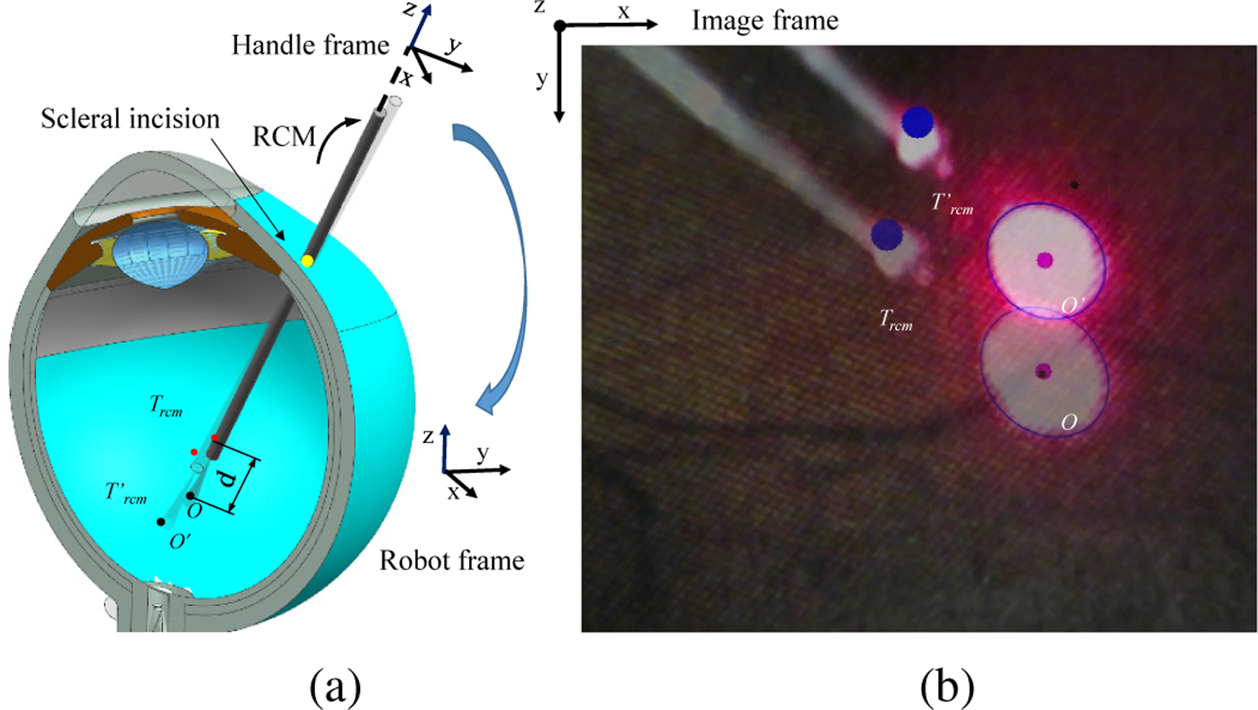
The robot visual servoing from projection point O to Oʹ. (a) The diagram of the visual servoing inside eye. (b) The microscope image view.
The SHER is a 5-DoF robot including three translational motions attributed to the robot base. The two rotary DoFs of the robot corresponds to the robot endeffector pitch and roll motions as depicted [27]. The cooperative control is realized by the force sensor installed on the end-effoctor of the SHER, which the control scheme follows,
| (8) |
where q is the position of each joint which equals [q1, q2, q3, q4, q5, 0], where the rotation around the instrument axis is not considered, is the velocity vector containing the velocity of each individual joint, is consists of the desired robot handle velocities in the robot frame (see Fig. 5(a) Fig. 6(b)), J†(q) is the pseudo inverse of the jacobian derived from the forward kinematics of the robot, is the desired robot handle velocities in the handle frame (see Fig. 6), kf is the proportional gain, F is the force applied on the instrument from operator’s hand which equals [fx, fy, fz, tx, ty, 0]. fx, fy, and fz denote the force on the x, y, z direction on the handle frame, respectively. tx and ty denote the toque on the x and y axis in handle frame, respectively. Arh is the adjoint transformation from the handle frame to the robot frame, which is represented as:
| (9) |
where Rrh and trh are the rotation matrix and translation matrix of rigid transformation from the handle frame to the robot frame. is the skew symmetric matrix that is associated with the vector trh.
Fig. 6.
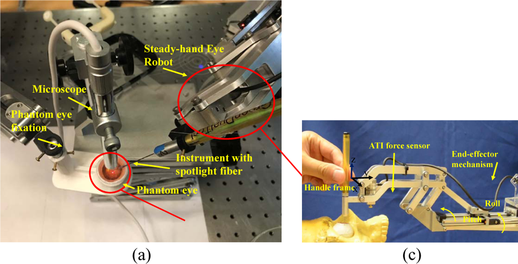
(a) The experiment setup. (b) The side view of time-lapse photography. (c) The end effector of SHER.
As soon as the needle is inserted through the insertion point of sclera, the RCM control mode is enabled with cooperative control mode, where the
| (10) |
where is the pseudo inverse of the jacobian with RCM constraint, λ is the insertion depth of the instrument, Frcm is the force on the handle frame in RCM mode which equals [0, 0, fZ, tX, tY, 0].
As soon as the visual servo mode is enabled the robot will be controlled by the target point on the image with RCM constraint. The image tracking algorithm will process the current projection pattern with 3D state information of the instrument tip which we denote Ircm as,
| (11) |
where Ox and Oy denote the point O in the image with pixel as the unit. ds is the distance from the tip to surface which can be inferred from with Eq. 7. The instrument tip state in handle frame Trcm related to Ircm can be obtained,
| (12) |
where A and B are the rotation matrix and translation vector between handle frame and image frame. Therefore the error model obtained between current Trcm and desired can be as follows,
| (13) |
where e is the deviation between Ircm and . Therefore the visual control scheme is set as,
| (14) |
where kv is the proportional gain. The rotation matrix A can be set to a identity matrix if the image frame is aligned to the handle frame.
IV. Experiment and result
A. Experiment setup
Fig. 6(a) showed the experimental setup. The instrument with light fiber is mounted on the SHER robot which is a cooperatively controlled 5-DoF robot for retinal surgery [28]. SHER is controlled by an off-the-shelf controller (Galil 4088, Galil, 270 Technology Way, Rocklin, CA 95765) and a 6 DoF Nano17 ATI force/torque sensor (ATI Industrial Automation, Apex, NC), shown in Fig. 6(c). The phantom is fixed with the phantom fixation.
B. Spotlight calibration
The spotlight is first calibrated to obtain the geometrical information. The fiber attached to the instrument is controlled to slightly touch the plane to sense the starting point. Following calibration, to record the ground truth of the end-tip to surface distance dr, the spotlight fiber on the robot is controlled to move with a speed of 0.1 mm/s in the Z direction of the end effector frame, as shown in Fig. 6 (c). δk can be calculated based on and dr using Eq. 3.
Three different starting points on the phantom plane are tested. The fitting result for average is shown in Fig. 7 (a). It is shown that the data is well fitted with the proposed model. The deviations of the fitted model may come from the touch method for defining the starting point and uneven plane. The root mean square error (RSME) for the average model is 0.163 mm.
Fig. 7.
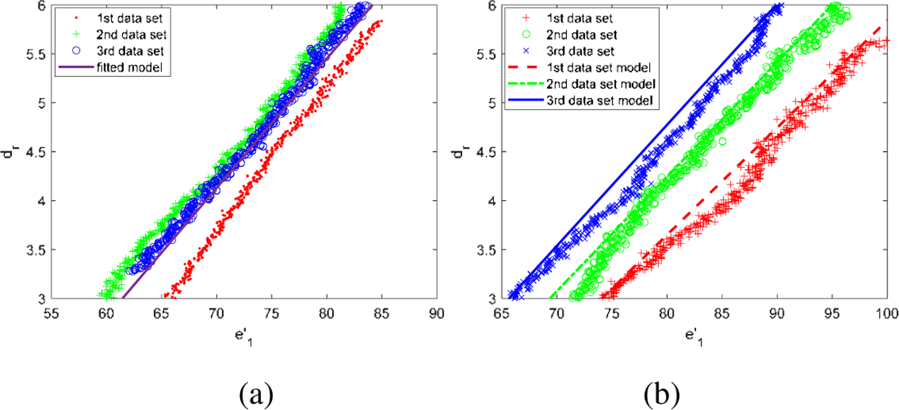
(a) The fitting result for average of three data set in the plane phantom. (b) The adjusted model with the ground truth distance in the eyeball phantom.
With the known δk and b with the previous deduction, in the eyeball phantom, we need to know c to estimate the distance from the end-tip to sphere surface. To test the performance of the estimation error on the eyeball phantom, three points located inside of the phantom eyeball are tested. The adjusted model with the ground truth distance is shown in Fig. 7 (b) which demonstrates that and dr are highly linear relationship.
SHER is controlled with cooperative control mode to test the dynamic performance of end-tip to surface distance estimation. The movement of the robot is controlled by the operator’s hand and the pose and position of the tool tip is calculated by the forward kinematics of the robot with 200 Hz frequency position information from the controller and joint sensor. The end-tip to surface distance is estimated with the frequency of 10 Hz by a USB microscope camera using the pose and position of the tool tip and the known plane in space. The plane formulation could be obtained by using the robot to touch more than three points on the plane surface. It is worth noticing that the touching of the points on the plane is only for formulating the phantom plane. The intersection point between the extension line of the spotlight end-tip and phantom surface can be calculated by the following equation,
| (15) |
where (e,f,g) is the normal of the plane, (m,n,p) is the direction vector of the instrument, (x1,y1,z1) and (x2,y2,z2) are the points on the plane and line, respectively. With known the intersection point on the surface and the end-tip of spotlight, the distance ground truth of distance can be calculated.
The spherical eyeball can also be formulated by touching four points on the eyeball surface, which is to formulate the eye ball surface and providing the ground truth for estimation. The intersection point can be calculated by following equation,
| (16) |
where (x3,y3,z3) is the center of sphere.
Fig. 8(b) and (e) show the trends between the moving speed of the spotlight fiber and the estimated distance error, which a higher moving speed will cause a larger estimated distance error. This can be more directly observed Fig. 8(c) and (e), because the faster speed will cause blur of the image, therefore, having the unshaped pattern edge. A more sensitive camera or a more brightness of the light source may improve this. 0.5 mm can be an accepted error if we want to introduce this technique as keeping the safe distance between the instrument tip and the retinal surface during surgery. As shown in Fig. 8(c) and (e), to achieve an error of 0.5 mm, the moving speed of end-tip of instrument needs to be restricted within 1.5 mm/s in our scenario.
Fig. 8.
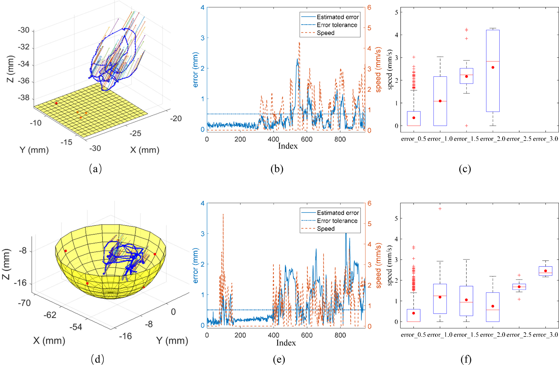
The trajectory of spotlight end-tip in 3D space on the phantom plane (a) and phantom eyeball (d). The red points are the touched points on the surface. The moving speed of the spotlight end-tip and the estimated error for the distance between end-tip and phantom surface during motion on the phantom plane (d) and phantom eyeball (e). The relationship of error group and speed. error_0.5 denotes the recorded error between 0 and 0.5. error_1.0 denotes the recorded error between 0.5 and 1.0. The same applies on error group of error_1.5, error_2.0, error_2.5, and error_3.0.
C. Single point visual servoing
The single point visual servoing tracking task is first performed using spotlight navigation with depth control and without depth control. The center of the spotlight is controlled to follow the black single point which is clicked by the mouse as shown in Fig. 9 (a) and (b). The safe distance is set within 4.0 to 4.5 mm and the tip to surface distance is range from 3.298 to 5.096 mm. While without safe distance control the tip to surface distance is 2.387 to 6.299 mm.
Fig. 9.
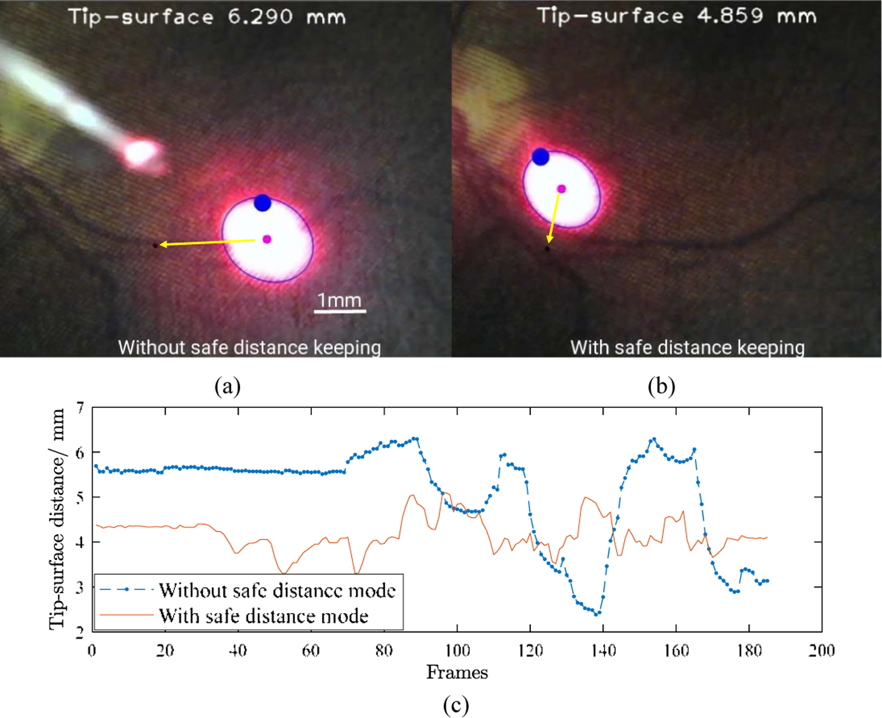
The single point visual servoing tracking without depth control (a) and with depth control (b). (c) The tip to surface distance changes with time frames.
D. Vessel tracking
The vessel tracking task in the phantom was performed to show the advantages of the proposed method. The aim of the task is to keep the center of the spotlight on the vessel while maintaining a designated safe distance within 4.0 to 4.5 mm during tracking. The vessel was marked by black pixels manually with the mouse clicking multi points, then the vessel is saved as a polyline for tracking. Three types of tracking operations were performed: manual tracking, robot-human cooperative tracking, and spotlight-based automatic tracking. The trajectory of the spotlight on the retinal phantom was recorded during the tracking to calculate the deviation of the trajectory of the spotlight and vessel. The experiment was repeated 5 times for each scenario. Fig. 10 shows the relationship between the tracking trajectory and vessel. It is noted that manual tracking is associated with the greatest hand tremor. The deviation in pixel between manual and robot-human cooperative tracking is similar with an overall mean error of 8.214 pixels and 7.632 pixels which are 0.099 mm and 0.092 mm, respectively, while the robot-human cooperative tracking is smoother. The automatic tracking has the best performance of tracking with an overall mean error of 1.069 pixels which is 0.013 mm.
Fig. 10.
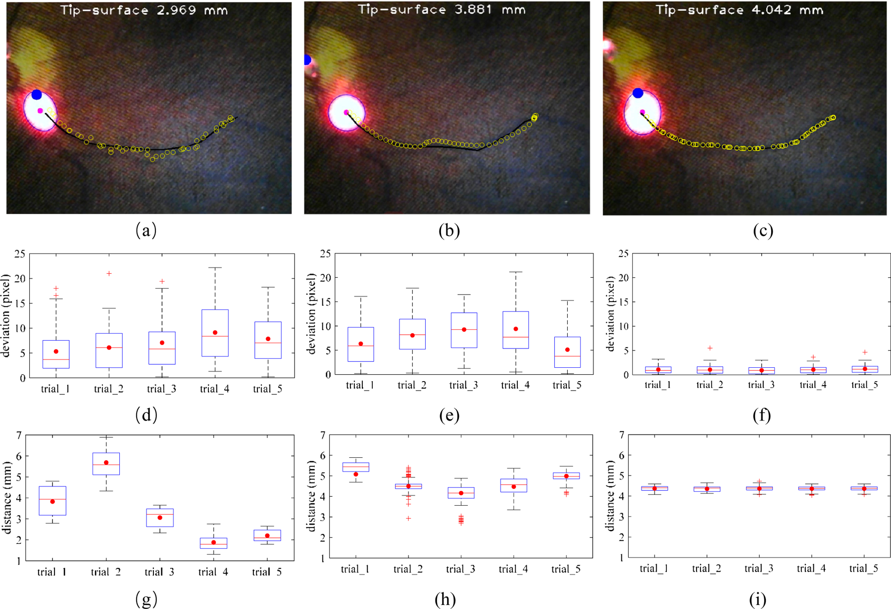
The comparison of three vessel tracking methods on the eye phantom. The manual tracking (a), cooperative control tracking with SHER (b), and spotlight-based automatic tracking with SHER (c). The black line is the vessel line for tracking. The blue circles are the spotlight center trajectories for each tracking trail. The tracking deviation between the target vessel and spotlight center trajectory with 5 times of the manual tracking (c), cooperative control tracking with SHER (d), and spotlight-based automatic tracking with SHER (e). The tip-to-surface distance calculated by the spotlight pattern for 5 times of the manual tracking (f), cooperative control tracking with SHER (g), and spotlight-based automatic tracking with SHER (i). The whiskers show the minimum and maximum recorded change of the recorded value while the first and third quartiles show the start and the end of the box. Band, red dot, and cross represent median, mean, and outliers of the recorded changes, respectively.
With regard to the maintenance of a safety barrier, manual tacking is inherently unsteady at 1.3–6.8 mm due to hand tremor and the need to keep a safe distance, and while simultaneously maintaining the RCM control. The robot-human cooperative tracking method performed better at 3.3–5.8 mm, as the robot arm provides reference without intention movement. The automatic tracking performed best under these conditions at 4.1–4.6 mm which is only 0.1 mm deviation from the target. The improved performance is attributed to the fact that the automatic tracking removed the human physiological tremor and human error from the control loop. The overall results showed that the automatic tracking result can, under the conditions modeled here, surpass both the manual and human-robot cooperative methods. These findings are directly applicable to improve the performance of retinal microsurgery.
V. Conclusion and future work
In this paper, we demonstrate a novel method for 3D guidance of an instrument using the projection of a spotlight in a single microscope image. The spotlight projection mechanism is analyzed and modeled on both a plane and a spherical surface. We then design and apply an algorithm to track and segment the spotlight projection pattern. Here the SHER with the spotlight setup, is used to verify the proposed method. We performed the vessel tracking task in an eye phantom with the RCM constraint. The results are compared to manual tracking, cooperative control tracking with SHER, and a spotlight-based automatic tracking method also with SHER. The experimental results showed that the static performance for end-tip to surface distance can be fitted well in the plane phantom and spherical eyeball phantom. With the designed tracking distance of 4.0–4.5 mm, the manual tracking, robot cooperative tracking, and spotlight-based automatic tracking have the tracking distance of 1.3–6.8 mm, 3.3–5.8 mm, and 4.1–4.6 mm, respectively. The comparisons of the three methods show that the proposed spotlight-based automatic tracking has a much better performance in tracking vessels and maintaining a prescribed safe distance. These results show the clear potential clinical value of the proposed methods in applications such are retinal microsurgery. Future work will focus on the design of a more clinically usable tool and transnational efforts via animal trails. Integration with an OCT image system in order to achieve large-scale tasks and fine localization for shortrange tasks is also interesting to explore.
Supplementary Material
Acknowledgment
The authors would like to acknowledge the Editor-In-Chief, Associate Editor, and anonymous reviewers for their contributions to the improvement of this article. We would like to thank the financial support from the U.S. National Institutes of Health (NIH: grants no. 1R01EB023943–01 and 1R01 EB025883–01A1) and TUM-GS internationalization funding. We also would like to thank the project of Research to Prevent Blindness, New York, New York, USA. The work of J. Wu was supported inpart by the HK RGC under T42–409/18-R and 14202918.
Footnotes
This paper was recommended for publication by Pietro Valdastri upon evaluation of the Associate Editor and Reviewers’ comments.
References
- [1].de Oliveira IF, Barbosa EJ, Peters MCC, Henostroza MAB, Yukuyama N, dos Santos Neto E, Löbenberg R, and Bou-Chacra N, “Cutting-edge advances in therapy for the posterior segment of the eye: Solid lipid nanoparticles and nanostructured lipid carriers,” International Journal of Pharmaceutics, p. 119831, 2020. [DOI] [PubMed]
- [2].Yang G-Z, Cambias J, Cleary K, Daimler E, Drake J, Dupont PE, Hata N, Kazanzides P, Martel S, Patel RV et al. , “Medical robotics-regulatory, ethical, and legal considerations for increasing levels of autonomy,” Sci. Robot, vol. 2, no. 4, p. 8638, 2017. [DOI] [PubMed] [Google Scholar]
- [3].Lu B, Chu HK, Huang K, and Cheng L, “Vision-based surgical suture looping through trajectory planning for wound suturing,” IEEE Transactions on Automation Science and Engineering, vol. 16, no. 2, pp. 542–556, 2018. [Google Scholar]
- [4].Nakano T, Sugita N, Ueta T, Tamaki Y, and Mitsuishi M, “A parallel robot to assist vitreoretinal surgery,” Int. J. Comput. Assist. Radiol. Surg, vol. 4, no. 6, pp. 517–526, 2009. [DOI] [PubMed] [Google Scholar]
- [5].Ang WT, Riviere CN, and Khosla PK, “Design and implementation of active error canceling in hand-held microsurgical instrument,” in Intelligent Robot. Syst. 2001 IEEE/RSJ Int. Conf, 2. IEEE, 2001, pp. 1106–1111. [Google Scholar]
- [6].Wei W, Goldman R, Simaan N, Fine H, and Chang S, “Design and theoretical evaluation of micro-surgical manipulators for orbital manipulation and intraocular dexterity,” in Robot. Autom. 2007 IEEE Int. Conf IEEE, 2007, pp. 3389–3395.
- [7].Taylor R, Jensen P, Whitcomb L, Barnes A, Kumar R, Stoianovici D, Gupta P, Wang Z, Dejuan E, and Kavoussi L, “A steady-hand robotic system for microsurgical augmentation,” Int. J. Rob. Res, vol. 18, no. 12, pp. 1201–1210, 1999. [Google Scholar]
- [8].Ullrich F, Bergeles C, Pokki J, Ergeneman O, Erni S, Chatzipir-piridis G, Pane S, Framme C, and Nelson BJ, “Mobility experiments with microrobots for minimally invasive intraocular SurgeryMicrorobot experiments for intraocular surgery,” Invest. Ophthalmol. Vis. Sci, vol. 54, no. 4, pp. 2853–2863, 2013. [DOI] [PubMed] [Google Scholar]
- [9].Meenink HCM, Rosielle R, Steinbuch M, Nijmeijer H, and De Smet MC, “A master-µslave robot for vitreo-retinal eye surgery,” in Euspen Int. Conf, 2010, pp. 3–6.
- [10].Rahimy E, Wilson J, Tsao TC, Schwartz S, and Hubschman JP, “Robot-assisted intraocular surgery: development of the IRISS and feasibility studies in an animal model,” Eye, vol. 27, no. 8, pp. 972–978, 2013. [DOI] [PMC free article] [PubMed] [Google Scholar]
- [11].Gijbels A, Vander Poorten E, Gorissen B, Devreker A, Stalmans P, and Reynaerts D, “Experimental validation of a robotic comanipulation and telemanipulation system for retinal surgery,” in 2014 5th IEEE RAS EMBS Int. Conf. Biomed. Robot. Biomechatronics IEEE, 2014, pp. 144–150.
- [12].Vander Poorten E, Riviere CN, Abbott JJ, Bergeles C, Nasseri MA, Kang JU, Sznitman R, Faridpooya K, and Iordachita I, “Robotic retinal surgery,” in Handbook of Robotic and Image-Guided Surgery Elsevier, 2020, pp. 627–672. [Google Scholar]
- [13].Kim JW, Zhang P, Gehlbach P, Iordachita I, and Kobilarov M, “Towards autonomous eye surgery by combining deep imitation learning with optimal control,” arXiv preprint arXiv:2011.07778, 2020. [PMC free article] [PubMed]
- [14].Zhou M, Yu Q, Mahov S, Huang K, Eslami A, Maier M, Lohmann CP, Navab N, Zapp D, Knoll A et al. , “Towards robotic-assisted subretinal injection: A hybrid parallel-serial robot system design and preliminary evaluation,” IEEE Transactions on Industrial Electronics, 2019.
- [15].Zhou M, Wu J, Ebrahimi A, Patel N, He C, Gehlbach P, Taylor RH, Knoll A, Nasseri MA, and Iordachita II, “Spotlight-based 3d instrument guidance for retinal surgery, to be appear.” in 2020 International Symposium on Medical Robotics (ISMR), May 2020. [DOI] [PMC free article] [PubMed]
- [16].Ebrahimi A, Alambeigi F, Sefati S, Patel N, He C, Gehlbach PL, and Iordachita I, “Stochastic force-based insertion depth and tip position estimations of flexible fbg-equipped instruments in robotic retinal surgery,” IEEE/ASME Transactions on Mechatronics, 2020. [DOI] [PMC free article] [PubMed]
- [17].Zhou M, Wang X, Weiss J, Eslami A, Huang K, Maier M, Lohmann CP, Navab N, Knoll A, and Nasseri MA, “Needle localization for robot-assisted subretinal injection based on deep learning,” in 2019 International Conference on Robotics and Automation (ICRA) IEEE, 2019, pp. 8727–8732.
- [18].Gerber MJ, Hubschman J-P, and Tsao T-C, “Automated retinal vein cannulation on silicone phantoms using optical coherence tomography-guided robotic manipulations,” IEEE/ASME Transactions on Mechatronics, 2020. [DOI] [PMC free article] [PubMed]
- [19].Yu H, Shen J-H, Joos KM, and Simaan N, “Calibration and integration of b-mode optical coherence tomography for assistive control in robotic microsurgery,” IEEE/ASME Transactions on Mechatronics, vol. 21, no. 6, pp. 2613–2623, 2016. [Google Scholar]
- [20].Song C, Park DY, Gehlbach PL, Park SJ, and Kang JU, “Fiberoptic OCT sensor guided “SMART” micro-forceps for microsurgery,” Biomed. Opt. Express, vol. 4, no. 7, pp. 1045–1050, 2013. [DOI] [PMC free article] [PubMed] [Google Scholar]
- [21].Cheon G-W, Huang Y, and Kang JU, “Active depth-locking handheld micro-injector based on common-path swept source optical coherence tomography,” in SPIE BiOS International Society for Optics and Photonics, 2015, pp. 93 170U–93 170U.
- [22].Weiss J, Rieke N, Nasseri MA, Maier M, Lohmann CP, Navab N, and Eslami A, “Injection assistance via surgical needle guidance using microscope-integrated oct (mi-oct),” Investigative Ophthalmology & Visual Science, vol. 59, no. 9, pp. 287–287, 2018. [Google Scholar]
- [23].Yang S, Martel JN, Lobes LA Jr, and Riviere CN, “Techniques for robot-aided intraocular surgery using monocular vision,” The International journal of robotics research, vol. 37, no. 8, pp. 931–952, 2018. [DOI] [PMC free article] [PubMed] [Google Scholar]
- [24].Routray A, MacLachlan RA, Martel JN, and Riviere CN, “Real-time incremental estimation of retinal surface using laser aiming beam,” in 2019 International Symposium on Medical Robotics (ISMR) IEEE, 2019, pp. 1–5.
- [25].Treuting PM, Wong R, Tu DC, and Phan I, “Special senses: eye,” in Comparative Anatomy and Histology Elsevier, 2012, pp. 395–418. [Google Scholar]
- [26].Zhou Y and Nelson BJ, “Calibration of a parametric model of an optical microscope,” Optical Engineering, vol. 38, 1999. [Google Scholar]
- [27].Ebrahimi A, Urias M, Patel N, He C, Taylor RH, Gehlbach P, and Iordachita I, “Towards securing the sclera against patient involuntary head movement in robotic retinal surgery,” in 2019 28th IEEE International Conference on Robot and Human Interactive Communication (RO-MAN) IEEE, 2019, pp. 1–6. [DOI] [PMC free article] [PubMed]
- [28].Ebrahimi A, Urias M, Patel N, Taylor RH, Gehlbach PL, and Iordachita I, “Adaptive control improves sclera force safety in robot-assisted eye surgery: A clinical study,” IEEE Transactions on Biomedical Engineering, 2021. [DOI] [PMC free article] [PubMed]
Associated Data
This section collects any data citations, data availability statements, or supplementary materials included in this article.


