Abstract
Cleveland Clinic is developing a continuous-flow total artificial heart (CFTAH). This novel design operates without valves and is suspended both axially and radially through the balancing of the magnetic and hydrodynamic forces. A series of long-term animal studies with no anticoagulation demonstrated good biocompatibility, without any thromboemboli or infarctions in the organs. However, we observed varying degrees of thrombus attached to the right impeller blades following device explant. No thrombus was found attached to the left impeller blades. The goals for this study were: 1) to use computational fluid dynamics (CFD) to gain insight into the differences in the flow fields surrounding both impellers, and 2) to leverage that knowledge in identifying an improved next-generation right impeller design that could reduce the potential for thrombus formation. Transient CFD simulations of the CFTAH at a blood flow rate and impeller rotational speed mimicking in vivo conditions revealed significant blade tip-induced flow separation and clustered regions of low wall shear stress near the right impeller that were not present for the left impeller. Numerous right impeller design variations were modeled, including changes to the impeller cone angle, number of blades, blade pattern, blade shape, and inlet housing design. The preferred, next-generation right impeller design incorporated a steeper cone angle, a primary/splitter blade design similar to the left impeller, and an increased blade curvature to better align the incoming flow with the impeller blade tips. The next-generation impeller design reduced both the extent of low shear regions near the right impeller surface and flow separation from the blade leading edges, while maintaining the desired hydraulic performance of the original CFTAH design.
Keywords: Blood pump, total artificial heart, computational fluid dynamics, thrombosis, wall shear stress, pump impeller, biocompatibility
INTRODUCTION
Heart failure (HF) is a critical healthcare issue that affects ~23 million people worldwide and is a primary source of cardiovascular mortality.1,2 In the United States, an estimated 50,000-100,000 patients per year need heart transplantation or mechanical circulatory support, but only ~3,500 transplants are performed. The use of left ventricular assist devices (LVADs) is becoming widely accepted, mainly due to the introduction of continuous-flow blood pumps.3 These pumps have significantly improved in size, simplicity, reliability, durability, and clinical results. However, up to 44% of patients undergoing LVAD implantation also have severe right ventricular (RV) failure.4 The HeartMate II investigators documented a 20% decrease in 1-year survival in patients who developed RV failure, which leads to the justification for total artificial heart (TAH) tCFechnology.5,6
The Cleveland Clinic’s continuous-flow total artificial heart (CFTAH) design introduces an innovative concept in TAH design.7 The current (adult) CFTAH, like the rest of the device portfolio (pediatric and infant) comprises a single, valveless continuous-flow pump with passive inherent hydraulic flow and pressure regulation to take over the function of the native heart.8,9 This “double-pump” concept has a single, continuously rotating, brushless DC motor and pump assembly with a centrifugal pump on both ends. Pump speed is modulated to create pulsatile flow and pressure. The core breakthrough of this pump concept is that the hemodynamic function of balancing systemic and pulmonary flows while minimizing atrial pressure differences is incorporated directly into the pump’s hydromechanical design. This inherent function is automatic, immediate, passive, and requires no electronic intervention.
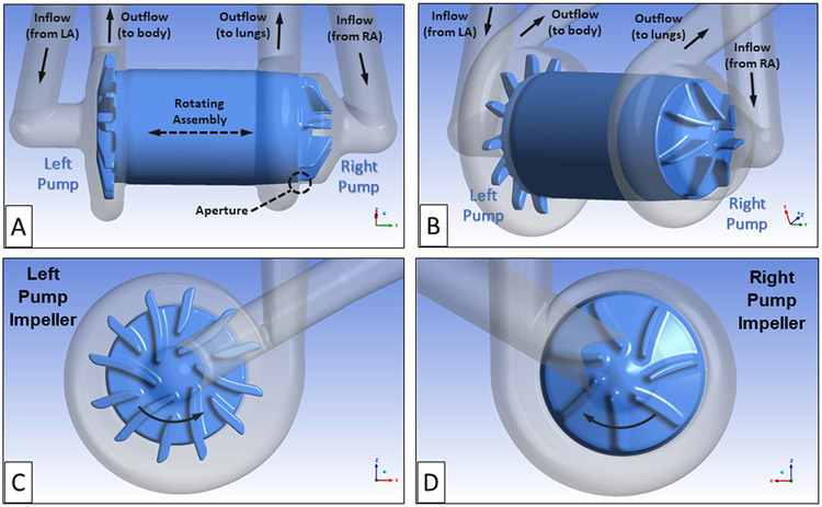
The flow path and geometry for the baseline continuous-flow total artificial heart (CFTAH), model 080 design, are shown in Figures 1A and B. The right pump moves the blood returning from the body, via the right atrium (RA), to the lungs. The left pump receives the blood returning from the lungs, via the left atrium (LA), and pumps that blood throughout the body. For this design, the rotor is free to move both axially and radially until it reaches a magnetic/hydrodynamic force-balanced position. A thin, blood-lubricated journal bearing flow path connects the right and left impeller flow regions.
Figure 1.
The CFTAH080 design showing the rotating assembly with left and right impeller regions, the thin connecting journal bearing blood flow path, and the right pump aperture. The right pump moves the blood returning from the body, via the right atrium (RA), to the lungs. The left pump receives the blood returning from the lungs, via the left atrium (LA), and pumps that blood throughout the body. (A) Side view of rotating assembly and blood flow path. (B) Isometric view of rotating assembly and blood flow path. (C) Left pump impeller with six primary blades and six splitter blades. (D) Right pump impeller with seven primary impeller blades. The direction of rotation is indicated by arrows.
Another unique feature of this pump is that the right pump includes a narrow fluid path, an aperture that connects the impeller region with the volute. This aperture functions as a differential pressure-regulating valve to automatically balance the right and left pump inlet pressures. The differential pressure-regulating feature keeps the right and left blood inlet pressures safely balanced.8
The left pump, composed of six primary impeller blades and six, smaller splitter blades, provides the hydraulic pressure head (60 to 110 mm Hg) to supply the body with oxygenated blood over its operating range (3 to 8 L/min). By comparison, the right pump has seven larger primary impeller blades without splitters. It was designed to supply the lower hydraulic pressure head required (20 to 40 mm Hg) to provide blood flow to and from the lungs.10 Images of the left and right impeller designs are shown in Figures 1 C and D.
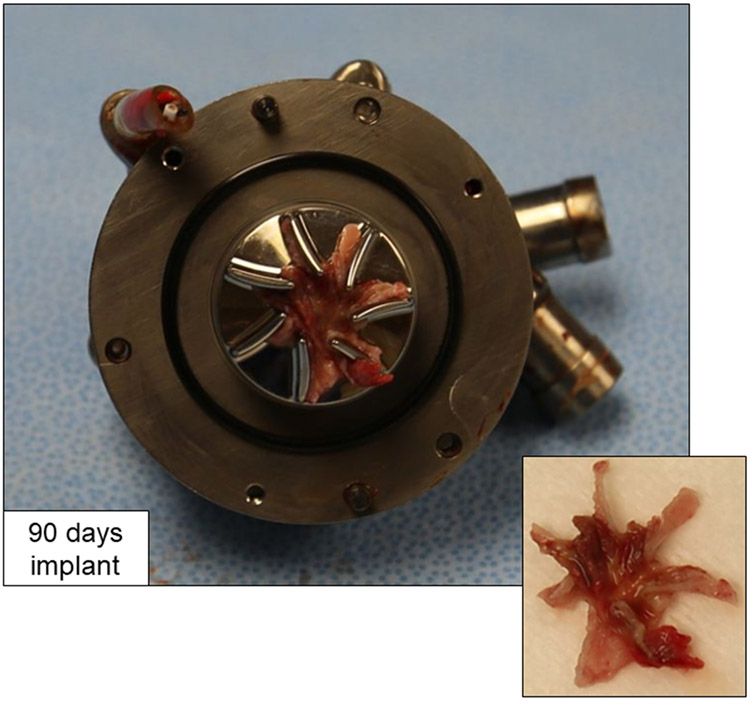
A series of four long-term animal studies was successfully performed with the CFTAH080, without administration of postoperative anticoagulation.11 Upon explant, there were no thromboemboli or infarctions in the organs. The blood flow paths for the pumps were clean, except for varying amounts of thrombus attached to the right pump impeller surfaces. The 14- and 30-day implanted devices showed small, localized thrombi near the impeller outer edges, typically between the impeller blades. One of the longer-duration, 90-day implanted pumps showed a larger, more formed thrombus on the right impeller surfaces. In that final 90-day implant, a star-shaped thrombus formed in between and predominantly along the downstream, suction side of the impeller blades (Figure 2).
Figure 2.
Right impeller surfaces showing attached star-shaped thrombus after explant of CFTAH080 device following intended 90-day duration in calf.
By comparison, the left pump impeller surfaces for all the explants were clean and free of thrombus. The primary goal for the current study was to leverage computational fluid dynamics (CFD) analyses performed at the in vivo flow conditions to identify differences in the flow patterns around the left and right impellers. Such differences could reveal potential reasons for the thrombus formations on the right impeller surfaces. With this insight, numerous right impeller designs were modeled with a goal of identifying an improved, next-generation right impeller design with a reduced likelihood of thrombus formation.
MATERIALS AND METHODS
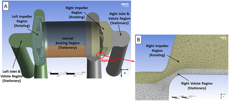
The CFTAH CFD simulations were performed using ANSYS 17.2 software (ANSYS Inc., Canonsburg, PA). The pump fluid volume was extracted from the three-dimensional CFTAH model and separated into rotating and non-rotating flow domains using the ANSYS DesignModeler software. Figure 3A shows a cross-sectional image of the CFTAH model revealing each of the different stationary and rotating fluid regions. To reduce the influence of the applied boundary conditions, inlet and outlet extensions (each six inches long) were added to the pump CFD model. The ANSYS-Meshing software was used to create a hybrid (tetrahedral, prism, hexahedral) mesh of typically near 19 million elements for the flow domains. A body sizing of 0.6 to 0.8 mm and face sizing of 0.04 to 0.60 mm were used to create the tetrahedral volume meshes for the pump regions. Prism or hexahedral boundary layers, eight elements thick, were used on all of the pump’s internal surfaces to capture the flow field and velocity gradients along the walls. A close-up view of the computational mesh through the aperture region of the right impeller is shown in Figure 3B.
Figure 3.
(A) Cross-sectional view of the CFTAH CFD model without the inlet and outlet cannula extensions. This image shows the rotating left and right impeller regions, the stationary left and right pump inlet and volute regions, and the stationary journal bearing region. (B) Cross-sectional view of the computational mesh used near the right pump aperture.
The CFTAH CFD model was previously validated by comparison with rotor torque and in vitro pressure mapping data over the intended range of operating conditions.12 For that study, steady state, frozen rotor CFD solutions were conducted using the ANSYS-CFX software with fluid properties matching the in vitro test conditions (ρ = 1078 kg/m3; μ = 2.63 centipoise). The shear stress transport (SST) k-ω turbulence model was used in these simulations.13 Constant static pressures were applied to both the left and right pump cannula inlets. A mass flow rate boundary condition was set for both the left and right pump cannula outlets. The values for these boundary conditions were determined from the corresponding set of test data.
For each flow condition modeled, the rotating assembly axial position was moved to a location that provided a right pump pressure increase equal to the in vitro test data. This axial rotor position, which as not available experimentally, was important to set accurately as the right pump pressure rise is strongly dependent on the aperture size. The area-averaged mesh y+ values, which is a dimensionless distance from the wall based upon the local wall shear stress, were below 1 for both the left and right pump impeller surfaces. This indicates that the first layer of elements, adjacent to the impeller surfaces, resides within the viscous sublayer and an appropriate level of near-wall mesh refinement to accurately predict the wall shear stress values.14 The CFD simulation results agreed with experimental values to within 5-10% for rotor torque, hydraulic pressure heads, and 10 static pressure taps placed at different locations throughout the pump. More specifically, for the 8 L/min and 3100 rpm flow condition which was used in this new study, the CFD predicted rotor torque was 9.5% higher than the measured value and the right pump static pressure taps within the impeller and volute regions were 3.8% higher and 9.2% lower than their corresponding measure values.
For the current work, the CFTAH CFD model was then used to compare and evaluate the flow fields near the right and left impeller surfaces using blood. A Cross non-Newtonian blood viscosity model15-18 was included to help identify low-shear stress regions. For the design comparison simulations, the blood flow rate was set at 8 L/min and the impeller rotational speed was 3,100 rpm to mimic the in vivo test conditions. For each set of flow conditions, the radial and axial locations of the rotating assembly were fixed at the same positions used in the previous in vitro model validation study. The static pressures were set to 2.9 mmHg and 9.6 mmHg for the right and left inflow cannulas, respectively. These values again matched the values from the previous in vitro model validation study. Mass flow rates of 0.141 kg/sec, corresponding to a volume flow rate 8 L/min, were applied at both pump cannula outlets.
Steady state frozen-rotor simulations were run first as starting solutions for the transient, rotor-stator analyses. For the transient simulations, a 1° rotation per time step was used. A second order backward Euler time stepping scheme was used with an RMS residual convergence criteria of less than 4e-05 per time step. The number of impeller full rotations varied from one to three, depending on the right impeller design studied. The ANSYS-CFD Post software was used to post-process and visualize the CFD results. The CFD simulations were run on a Penguin compute cluster (Penguin Computing, Fremont, CA) using 80 cores.
To extend the earlier validation study using water/glycerin, an updated mesh sensitivity study using blood at the 8 L/min and 3100 rpm rotor speed conditions was conducted. Table 1 summarizes the findings from this study, conducted using steady-state conditions. The largest difference was a 9.3% increase in peak shear stress comparing the coarser and refined mesh results. A much smaller 1.9% difference in right impeller torque and 4.1% increase in right pump pressure rise resulted from increased mesh refinement. When comparing the fine mesh results, relatively small changes were found when changing from water/glycerin to blood. With blood, the right pump’s pressure decreased by 9.4%, the impeller torque increased by 1.2%, and the impeller surfaces with low wall shear stress were very similar. As the right impeller flow field is turbulent, inertial forces should dominant over the viscous forces reducing the impact of blood’s increased viscosity. These findings support the use of the refined mesh model used in the present study.
Table 1.
Summary of the mesh refinement study results using blood at 8 L/min and 3100 rpm impeller speed conditions.
| Mesh Refinement Level |
Number of Elements (millions) |
Peak Wall Shear Stress (dyne/cm2) |
Average Wall Shear Stress (dyne/cm2) |
Impeller Torque (N*m) |
Pressure Rise (mmHg) |
Average Impeller Yplus |
|---|---|---|---|---|---|---|
| Coarser | 9.8 | 8,180 | 905 | 0.00691 | 22.0 | 1.82 |
|
Middle
(%Δ from Coarse Mesh) |
12.7 (30%) |
8,400 (2.7%) |
894 (−1.2%) |
0.00694 (0.4%) |
21.8 (−0.9%) |
1.56 (−14.3%) |
|
Refined
(%Δ from Coarse Mesh) |
19.0 (95%) |
8,940 (9.3%) |
867 (−4.2%) |
0.00704 (1.9%) |
22.9 (4.1%) |
1.33 (−26.9%) |
With a goal of identifying a new right impeller design with the potential to eliminate thrombus formation, numerous design variations were explored. These changes were intended to remove regions with sustained low wall shear stress on the impeller surfaces, where thrombus could form.19-23 In addition to improving the right pump’s flow characteristics, it was important to maintain the hydraulic performance of the baseline right pump design.
To reduce the extent of low wall shear stress regions, three designs with reduced flow area between the impeller blades were modeled. The first concept changed the number of primary impeller blades from seven to six and added six smaller splitter blades in between the primary blades. This configuration, resembling the left impeller design, has increased blade surface area intended to increase the pressure head. Another approach was to use wedge-shaped impeller blades with increased width moving radially outwards. A third design increased the impeller surface cone angle from 15° to 25°.
To evaluate the impact of the inlet design on the flow patterns approaching the impeller blades and within the blade passages, three different right impeller inlet designs were evaluated. These designs included a 5 mm extension between the incoming 90° elbow and the impeller chamber, an expanded inlet diameter, and an inlet nozzle-like design.
Three additional design concepts aimed at improving the alignment between the incoming flow and the impeller blade tips, with a goal of reducing the leading edge-induced flow separation, were also modeled. For the first concept, the blade curvature was increased by reducing the leading-edge blade angle from 50° to 38°, relative to the horizontal, to better align the incoming flow with the impeller blade tips. Two other concepts, a flat center and a steeper cone center, were also explored.
RESULTS
Baseline CFTAH080 Design - Left vs. Right Impeller Flow Fields
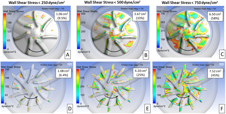
The first step in this study was to identify flow-related differences between the left and right impeller regions that could lead to thrombus deposition. As a starting point, the wall shear stress acting on the impeller surfaces was compared at several lower shear stress levels. The intent was to define a shear stress level that reflects the shape, extent, and location of the thrombus observed. Figure 4 presents the wall shear stress acting on the right (A, B, C) and left (D, E, F) impeller surfaces at three stress levels after 720° of rotation. The surface area and percentage of each impeller’s surface area with stress levels at or below the three levels is shown on each image. These numbers represent average values from 360° to 720° of rotation. The intent was to capture the transient change in the impeller wall shear stress values as the impeller spins. The right impeller exhibits lower absolute values for the surface area below each shear stress threshold. However, the area percentages (low shear area divided by total surface area) are higher for the right impeller (11.1 cm2) which is 50% smaller in area than left impeller (16.8 cm2). In addition, the low shear regions for the right impeller are clustered versus more dispersed for the left impeller.
Figure 4.
Contours showing areas of low wall shear stress on the right and left impeller surfaces. Three levels of wall shear stress are presented 250 (A, B), 500 (C, D), and 750 (E, F) dyne/cm2. The area and percentage of the impeller surface area with wall shear stress below each of these three levels is provided in each image. The direction of rotation is indicated by the arrows.
For the design comparison study, a wall shear stress level of 500 dyne/cm2 was selected to define the extent of the low shear region. This shear level reveals the clusters of low shear values between the impeller blades and near the center region. Both regions are consistent with the locations of thrombus observed from the explanted pump. The 500 dyne/cm2 also provides a mid-level baseline value of the low shear regions where the impact of right impeller design changes would be more quantifiable.
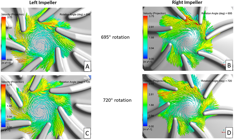
Identifying regions of flow separation near the impeller blades was the other key areas of focus. In-plane velocity vectors, relative to the rotating frame of reference, on planes near the mid-level of the impellers are shown in Figure 5. Figure 5 compares the blade tip velocity vector fields after 695° and 720° of impeller rotation for the left (A, C) and right (B, D) impellers, respectively. Minimal blade leading edge-initiated flow separation was observed for the left impeller design, compared with significant flow separation originating from several (12:00 to 3:00 position) of the right impeller blades. These flow separation regions compare well with the low wall shear and observed thrombus locations for the right impeller shown in Figures 2 and 4.
Figure 5.
In-plane velocity vectors, relative to the rotating frame of reference, for the left and right impellers after 695° (A, B) and 720° (C, D) of rotation. The plane used in these images is near the mid-level for each impeller blade.
Right Impeller Design Changes
To reduce both the extent of low shear stress regions between the impeller blades and the degree of leading-edge blade-induced flow separation, numerous right impeller design variations were explored. The design modifications include changes to the impeller surface cone angle, blade curvature, blade width and pattern, inlet design, and impeller center region. The following sections discuss the findings and observations resulting from these design changes.
Reducing the Flow Area between Impeller Blades
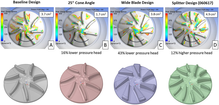
Images showing the extent of the low wall shear stress regions for the baseline and three impeller designs intended to reduce the flow area between the impeller blades, after 360° of rotation, are presented in Figure 6. Increasing the impeller surface cone angle from 15° to 25° significantly reduced the area of low wall shear stress from 3.7 cm2 for the baseline design to 1.7 cm2. The low shear area between the impeller blades was noticeable reduced for this design. The disadvantage with increasing the cone angle was a 16% reduction in the pump pressure rise compared with the baseline design. The wide blade design slightly increased the low shear area, from 3.8 to 3.7 cm2, but reduced the pump pressure head by 43%. With its larger blade surface area, the splitter design increased both the low shear area to 4.9 cm2 and the pump pressure rise by 12%.
Figure 6.
Contours showing areas of wall shear stress below 500 dyne/cm2 on the right impeller surface for the baseline (A) and three other designs (B, C, D), intended to reduce the fluid volume between the impeller blades. The impeller surface area with wall shear below 500 dyne/cm2, averaged over 360° of rotation, and the change in pressure head vs. the baseline design are provided for each design. The direction of rotation is indicated by the arrows.
Assessing Influence of the Inlet Design
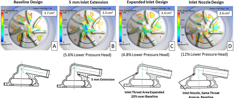
To evaluate the impact of the inlet design on the flow patterns approaching the impeller blades and within the blade passages, three different right impeller inlet configurations were evaluated. Cross-sectional images of the baseline and inlet design variations, with their corresponding plots showing low shear regions, are provided in Figure 7. Each of the design variations showed a small reduction in the area of low wall shear stress, but also resulted in a 5 to 12% reduction in pressure head compared with the baseline design.
Figure 7.
Contours showing areas of wall shear stress below 500 dyne/cm2 on the right impeller surface for the baseline (A) and three alternate inlet designs (B, C, D). The impeller surface area with wall shear below 500 dyne/cm2, averaged over 360° of rotation, and the change in pressure head vs. the baseline design are provided for each design. The direction of rotation is indicated by the arrows.
Evaluating Blade Curvature and Center Region Design
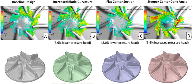
Several design concepts aimed at improving the alignment between the incoming flow and the impeller blade tips, with a goal of reducing the leading edge-induced flow separation, were also modeled. A comparison of in-plane velocity vectors, relative to the rotating frame of reference, on a plane near the mid-level of the impellers for the baseline and three blade/center impeller region design variations is presented in Figure 8. Reducing the leading-edge blade angle and increasing the center cone angle improved the alignment of the incoming flow with the impeller blade tips. This improved flow/blade tip alignment should reduce the extent of flow separation downstream of the blade leading edges. The steeper center cone angle design increased the pressure head by 6%, whereas the other two designs reduced the pressure head by 8% compared with the baseline design.
Figure 8.
In-plane velocity vectors, relative to the rotating frame of reference, for the baseline (A) and three different blade/center impeller region designs (B, C, D) after 360° of rotation. The plane used for these images is near the mid-level for each right impeller blade.
Next-Generation Right Impeller Design
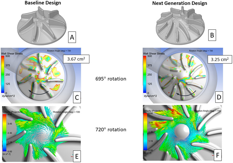
Leveraging the knowledge gained through the CFD results for the design variations modeled, a configuration was selected for the next-generation CFTAH right impeller design. This new design combined several features from the simulated designs, including a 25° impeller surface cone angle, six primary/six splitter blades, and a reduction in the leading-edge blade angle. An additional feature, 2:1 elliptical-shaped leading edges on all the impeller blades, was also included in the new design. This feature was intended to further reduce the extent of blade leading edge-initiated flow separation.24 All the previously modeled designs had spherically shaped, fully rounded impeller blade tips. Figures 9 A and B show the changes made between the baseline and next-generation right impeller designs.
Figure 9.
Isometric images of the baseline (A) and proposed next generation (B) right impeller designs. Contour plots showing areas of wall shear stress below 500 dyne/cm2 on the right impeller surface for the baseline (C) and next generation (D) designs. The impeller surface area with wall shear below 500 dyne/cm2, averaged from 360° to 720°of rotation, is provided in each image. The direction of impeller rotation is indicated by the arrows. In-plane velocity vectors, relative to the rotating frame of reference, for the baseline (E) and next generation (F) right impeller design after 720° of rotation. The plane used in these images is near the mid-level for each right impeller blade.
The changes included in the next-generation right impeller design reduced the impeller surface area with wall shear stress less than 500 dyne/cm2 from 3.67 cm2 for the baseline design to 3.25 cm2, a 11% improvement (Figures 9 C and D). These low shear area values were averaged from 360° to 720° of impeller rotation. In addition, the low shear regions for the new design were more disperse as was also seen for the left impeller. This reduced clustering of low shear regions should be beneficial in reducing the likelihood of thrombus formation.
Significant improvement in the alignment of the incoming flow with the leading edges of the primary impeller blades was also achieved with the next-generation design. In-plane, velocity vectors, relative to the rotating frame of reference, on a plane near the mid-level of the impellers, after 720° of impeller rotation, are shown in Figures 9 E and F. The number of impeller blades with leading edge-induced flow separation is reduced from three (12:00 to 3:00 positions) to one (2:00 position) with the next-generation design. This reduction in the leading edge-induced flow separation should reduce the extent of flow separation along the suction side of the impeller blades. And, as a result, help reduce the likelihood of thrombus formation in between the right impeller blades.
The next-generation right impeller design provided a pressure rise of 27.2 mmHg, compared with a 27.7 mmHg pressure rise for the baseline model at the 8 L/min and 3100 rpm impeller rotational speed condition. These were values averaged over a full impeller rotation from 360° to 720°. Therefore, the next-generation right impeller design should provide the desired pressure rise generated by the current baseline design.
DISCUSSION
Major advances have been achieved in recent years with durable total artificial heart (TAH) designs. Rotary blood pumps have gained increased use as mechanical circulatory assist devices.3 With their smaller size compared with positive displacement pumps, and having only one moving part, rotary pumps have been shown good long term durability post-implant.25 Leveraging the clinical success, mechanical simplicity, and durability of rotary pump LVADs, this technology has been expanded to TAH support.26
The BiVACOR and CFTAH are two examples of continuous-flow TAH pump designs. Both pumps use two impellers, coupled on the same rotating assembly, one providing for pulmonary flow and the other for systemic circulation. The primary differences between these designs is the means of rotor suspension and the method of balancing left/right pump performance. The BiVACOR uses a completely electromagnetic suspension for the rotating assembly and electronically controlled regulation.27 The CFTAH uses passive magnetic forces between the steel laminations in the motor and rotor magnet for rotor stability and a blood lubricated hydrodynamic journal bearing for rotor radial suspension. CFTAH performance regulation is also automatic and passive by balancing pressure forces against magnetic forces to move the rotor and alter relative left/right pump performance to balance atrial pressures.
Another rotary pump currently under development is the Orcorazon TAH.26 This design uses a single moving part that inherently produces physiologically pulsatile flow and consists of a single impeller on a moving rotor that shuttles to alternately pump blood to the pulmonary and systemic circulations, allowing more pulsatile output. The rotor consists of a hollow shaft with centrally located impeller blades and is suspended on blood lubricated hemodynamic bearing. As the Orcorazon TAH has a single impeller for both the left and right circulatory systems, hydraulic performance for both flow paths is very similar, and performance regulation is controlled by adjusting the timing of rotor position.
The CFTAH, with its unique aperture functioning as a differential pressure-regulating valve, automatically balances the right and left inlet pressures without any sensors needed to control the axial movement of the rotor. The additional flow resistance provided by the aperture adjusts right and left pump hydraulic performance needed for pulmonary (lower pressures) and systemic (higher pressures) circulation.
The CFTAH right and left impellers both have additional axial clearance to accommodate the passive axial movement of the rotating assembly. With this additional axial clearance, there are constant recirculation paths along the surfaces of the housing that spiral inwards towards each inlet. This leakage flow towards the inlet is unavoidable and impedes efficiency, but performance is compensated for by increased blade height and increased flow between the impeller blades for a given pump output. These recirculating flow paths are captured in the current CFD results, but not explicitly discussed in this manuscript which focuses instead on quantifying the extent of low shear stress regions on the right impeller surface where thrombus could form.
The initial CFD simulations revealed clusters of low shear stress regions between the impeller blades and flow separation originating near the leading edge of the right impeller blades. By comparison, even though the low shear stress area was larger for the left impeller, the low shear regions were much more sparsely distributed. Flow separation off the leading edges of the impeller blades was not seen for the left pump. Overall, the regions identified through the CFD analyses--the suction side of the right impeller blades--were consistent with the locations of the star-shaped thrombus that formed during the final long-term in vivo study.
Numerous right impeller design variations were modeled, including changes to the impeller surface cone angle, blade width, blade shape, number of blades, housing inlet configuration, and center region design. The intent of the design changes was to reduce the extent of low shear stress between the impeller blades and reduce flow separation that occurred near the blade leading edges. For each design change there was a trade-off between reducing the right impeller surface area with low shear stress and maintaining the desired right pump hydraulic performance.
Building upon the knowledge gained through modeling the design variations, we identified a next-generation right impeller design. This new design incorporated a steeper impeller surface cone angle (from 15° to 25°), a primary/splitter blade design, a reduced leading edge blade angle (from 50° to 35°), and an elliptical leading edge for the impeller blades. These changes reduced the flow separation off the primary impeller blades and reduced the impeller surface area with low shear stress by 11%, compared with the baseline design. The next-generation design also provided a hydraulic pressure head within 2% (27.2 vs. 27.7 mmHg) of the baseline design.
Limitations
A limitation of the current study is the assumption of constant flow/impeller speed conditions and a fixed axial location of the rotating assembly. During the in vivo tests and future clinical use, the axial position of the rotating assembly would be constantly shifting as the impeller speed varied, due to the intended sinusoidal speed modulation and to meet the metabolic needs of the patient. It would be very demanding, computationally, to move the rotating assembly axially into a force-balanced position with each incremental rotation of the impeller. Also, without knowing the pressure pulse wave that the pump is experiencing, the corresponding pressure boundary conditions could not be applied for the simulations. Therefore, the authors decided to perform the comparative study at the nominal high flow/high speed conditions at a constant axial position of the rotating assembly that approximates the conditions observed in the animal in vivo studies.
Another limitation of this study is the change in impeller blood flow patterns resulting from the onset and growth of the thrombus. As the thrombus grew, the local shear stress and flow recirculation zones near the impeller likely changed. However, without knowing how the thrombus growth progressed, the ability to simulate the changing impeller shape and the impact on the local flow field was not practical. Therefore, this study focused on identifying flow conditions near the right impeller surfaces that could initiate thrombus formation consistent with the star-shaped thrombus found after the in vivo testing of the initial CFTAH080 design.
CONCLUSIONS
A CFD study that compared the differences in the low wall shear stress patterns on the left versus right impeller for the Cleveland Clinic’s CFTAH was completed. The goal was to provide insight into the reasons for thrombus formation occurring on the right, but not the left impeller. Then, with that insight, to simulate different right impeller designs and identify a next-generation design with the potential to reduce areas of sustained low-shear stress and flow recirculation that could lead to thrombus formation. Numerous right impeller design variations were modeled under transient flow conditions for this comparison study. The preferred, next-generation right impeller design incorporated several changes that reduced the degree of flow separation and low wall shear stress within the blade passages, while providing the desired hydraulic performance.
The next step for the program is to build and test the CFTAH using the next-generation right impeller design. The upcoming tests include in vitro hydraulic performance testing, in vitro hemolysis testing, and short- and long-term animal studies. The findings from these studies will be compared with the predictions from the CFD simulations to demonstrate the overall performance of the updated design and further support the continued evolution of the CFTAH.
Acknowledgements
This work was supported with federal funding obtained from the National Heart, Lung and Blood Institute, National Institutes of Health (NHLBI), under grant R01 HL096619.
Footnotes
Conflicts of interest
DH and BK are device co-inventors. The technology is owned by Cleveland Clinic. Other authors report no conflicts.
References
- 1.Go AS, Mozaffarian D, Roger VL, et al. : American Heart Association Statistics Committee, and Stroke Statistics Subcommittee. Executive summary: heart disease and stroke statistics--2014 update: a report from the American Heart Association. Circulation 129 (3): 399–410. PMCID: PMC2891613, 2014. doi: 10.1161/01.cir.0000442015.53336.12. [DOI] [PubMed] [Google Scholar]
- 2.McMurray JJ, Petrie MC, Murdoch DR, Davie AP: Clinical epidemiology of heart failure: public and private health burden. European heart journal 19 Suppl P: P9–16, 1998. [PubMed] [Google Scholar]
- 3.Holman WL, Pae WE, Teutenberg JJ, et al. : INTERMACS: interval analysis of registry data. J Am Coll Surg 208 (5): 755–61; discussion 761-2, 2009. doi: S1072-7515(08)01659-1 [pii] 10.1016/j.jamcollsurg.2008.11.016. [DOI] [PubMed] [Google Scholar]
- 4.Drakos SG, Janicki L, Horne BD, et al. : Risk factors predictive of right ventricular failure after left ventricular assist device implantation. Am J Cardiol 105 (7): 1030–5, 2010. doi: 10.1016/j.amjcard.2009.11.026. [DOI] [PubMed] [Google Scholar]
- 5.Kormos RL, Teuteberg JJ, Pagani FD, et al. : HeartMate II Clinical Investigators. Right ventricular failure in patients with the HeartMate II continuous-flow left ventricular assist device: incidence, risk factors, and effect on outcomes. The Journal of thoracic and cardiovascular surgery 139 (5): 1316–24, 2010. doi: 10.1016/j.jtcvs.2009.11.020. [DOI] [PubMed] [Google Scholar]
- 6.Copeland JG 3rd, Smith RG, Arabia FA, et al. : Comparison of the CardioWest total artificial heart, the Novacor left ventricular assist system and the Thoratec ventricular assist system in bridge to transplantation. Ann Thorac Surg 71 (3 Suppl): S92–7; discussion S114-5, 2001. [DOI] [PubMed] [Google Scholar]
- 7.Horvath D, Byram N, Karimov JH, et al. : Mechanism of Self-Regulation and In Vivo Performance of the Cleveland Clinic Continuous-Flow Total Artificial Heart. Artif Organs 41 (5): 411–417, 2017. doi: 10.1111/aor.12780. [DOI] [PubMed] [Google Scholar]
- 8.Karimov JH, Horvath DJ, Fukamachi K: Cleveland Clinic total artificial heart. In Karimov JH, Fukamachi K, Starling RC, ed. Mechanical Support for Heart Failure: Current Solutions and New Technologies. Springer; p. 493–504, 2020. 10.1007/978-3-030-47809-4_30#DOI [DOI] [Google Scholar]
- 9.Fukamachi K, Karimov JH, Miyamoto T: Progress on total artificial heart for pediatric patients. In Karimov JH, Fukamachi K, Starling RC, ed. Mechanical Support for Heart Failure: Current Solutions and New Technologies. Springer; p. 599–608, 2020. 10.1007/978-3-030-47809-4_38#DOI [DOI] [Google Scholar]
- 10.Sunagawa G, Horvath DJ, Karimov JH, Moazami N, Fukamachi K: Future Prospects for the Total Artificial Heart. Expert review of medical devices 13 (2): 191–201, 2016. doi: 10.1586/17434440.2016.1136212. [DOI] [PubMed] [Google Scholar]
- 11.Karimov JH, Horvath DJ, Okano S, et al. : Thrombotic Depositions on Right Impeller of Double-Ended Centrifugal Total Artificial Heart In Vivo. Artif Organs 41 (5): 476–481, 2017. doi: 10.1111/aor.12778. [DOI] [PubMed] [Google Scholar]
- 12.Kobayashi M, Horvath DJ, Mielke N, et al. : Progress on the design and development of the continuous-flow total artificial heart. Artif Organs 36 (8): 705–13. PMCID: PMC3579623, 2012. doi: 10.1111/j.1525-1594.2012.01489.x. [DOI] [PMC free article] [PubMed] [Google Scholar]
- 13.Menter FR: Two-equation eddy-viscosity turbulence models for engineering applications. AIAA J 32(8): 1598–1605, 1994. [Google Scholar]
- 14.ANSYS-CFX Modeling Guide, Chapter 4, Turbulence and Near-Wall Modeling, Modeling Flow near the Wall, Version 2020R1.
- 15.Banerjee RK, Cho YI, Kensey K: Effect of non-Newtonian viscosity of blood on steady and pulsatile flow in stenosed arteries. American Society of Mechanical Engineers, Bioengineering Division (Publication) BED 20: 103–106, 1991. [Google Scholar]
- 16.Cross MM: Rheology on non-Newtonian fluids: a new flow equation for pseudoplastic systems. J Colloid Sci 20: 417–437, 1965. [Google Scholar]
- 17.Cho YI, Kensey KR: Effects of the non-Newtonian viscosity of blood on flows in a diseased arterial vessel. Part 1: Steady flows. Biorheology 28 (3-4): 241–62, 1991. doi: 10.3233/bir-1991-283-415. [DOI] [PubMed] [Google Scholar]
- 18.Hund SJ, Kameneva MV, Antaki JF: A Quasi-Mechanistic Mathematical Representation for Blood Viscosity. Fluids 2017, 2, 10; doi: 10.3390/fluids2010010. [DOI] [Google Scholar]
- 19.Glover CJ, McIntire LV, Leverett LB, Hellums JD, Brown CH, Natelson EA: Effect of shear stress on clot structure formation. Trans Am Soc Artif Intern Organs 20 B: 463–8, 1974. [PubMed] [Google Scholar]
- 20.Hellums JD, Peterson DM, Stathopoulos NA, Moake JL, Giorgio TD: Studies on the Mechanisms of Shear-Induced Platelet Activation. In: Hartmann A, Kuschinsky W (Eds.), Cerebral Ischemia and Hemorheology. Springer, Berlin, Heidelberg, pp. 80–89, 1987. [Google Scholar]
- 21.Bluestein D, Niu L, Schoephoerster RT, Dewanjee MK: Fluid mechanics of arterial stenosis: relationship to the development of mural thrombus. Ann Biomed Eng 25 (2): 344–56, 1997. doi: 10.1007/BF02648048. [DOI] [PubMed] [Google Scholar]
- 22.Einav S, Bluestein D: Dynamics of blood flow and platelet transport in pathological vessels. Ann N Y Acad Sci 1015: 351–66, 2004. doi: 10.1196/annals.1302.031. [DOI] [PubMed] [Google Scholar]
- 23.Chiu WC, Slepian MJ, Bluestein D: Thrombus formation patterns in the HeartMate II ventricular assist device: clinical observations can be predicted by numerical simulations. ASAIO J 60 (2): 237–40, 2014. doi: 10.1097/MAT.0000000000000034. [DOI] [PMC free article] [PubMed] [Google Scholar]
- 24.Davis MR: Design of flat plate leading edges to avoid separation. AIAA J 18(5): 598–600, 1980. [Google Scholar]
- 25.Mehra MR, Goldstein DJ, Uriel N, et al. : Two-Year Outcomes with a Magnetically Levitated Cardiac Pump in Heart Failure. N Engl J Med 378 (15): 1386–1395, 2018. doi: 10.1056/NEJMoa1800866. [DOI] [PubMed] [Google Scholar]
- 26.Glynn J, Wampler R: A novel rotary total artificial heart using a single shuttling impeller In Karimov JH, Fukamachi K, Starling RC, ed. Mechanical Support for Heart Failure: Current Solutions and New Technologies. Springer; p. 545–554, 2020. 10.1007/978-3-030-47809-4_33#DOI [DOI] [Google Scholar]
- 27.Timms DL, Nestler F: BiVACOR Total Artificial Heart. In Karimov JH, Fukamachi K, Starling RC, ed. Mechanical Support for Heart Failure: Current Solutions and New Technologies. Springer; p. 563–575, 2020. 10.1007/978-3-030-47809-4_35#DOI [DOI] [Google Scholar]


