Abstract
Vagus nerve stimulation (VNS) is a method to treat drug-resistant epilepsy and depression, but therapeutic outcomes are often not ideal. Newer electrode designs such as intra-fascicular electrodes offer potential improvements in reducing off-target effects but require a detailed understanding of the fascicular anatomy of the vagus nerve. We have adapted a section-and-image technique, cryo-imaging, with UV excitation to visualize fascicles along the length of the vagus nerve. In addition to offering optical sectioning at the surface via reduced penetration depth, UV illumination also produces sufficient contrast between fascicular structures and connective tissue. Here we demonstrate the utility of this approach in pilot experiments. We imaged fixed, cadaver vagus nerve samples, segmented fascicles, and demonstrated 3D tracking of fascicles. Such data can serve as input for computer models of vagus nerve stimulation.
Keywords: cryo-imaging, nerve anatomy, vagus nerve, fascicles
1. INTRODUCTION
Vagus nerve stimulation (VNS) is a type of neuromodulation that is clinically approved by the FDA to treat drug-resistant epilepsy, depression and obesity and is in clinical trials for other conditions such as hypertension, heart failure and rheumatoid arthritis1. However, treatment efficacy has been found to be limited, e.g., only 50% of patients undergoing VNS for treating drug-resistant epilepsy see a clinically significant reduction in seizure frequency2,3 and nearly the same fraction experience off-target effects such as dyspnea, cough and voice alteration4.
The off-target effects with VNS can be reduced, but a detailed map of the nerve’s fascicular anatomy is required to develop suitable treatment strategies. Traditional neuromodulation devices (e.g., cuff electrodes in VNS) suffer from low selectivity in nerve fiber stimulation, resulting either from incomplete stimulation of the target fibers or from the unwanted activation of motor nerve fibers5. Fewer off-target effects can potentially be achieved by using intra-fascicular electrodes, which are capable of stimulating certain fascicles in the nerve6,7. However, an in-depth understanding of the fascicular anatomy of the vagus nerve and its branches is required to adapt such designs and provide effective stimulation in the context of VNS. Additionally, mapping fascicular anatomy of the vagus nerve will improve the accuracy of computational models developed to better understand the effects of various neuromodulation device designs and stimulation parameters8.
Imaging vagus nerve anatomy at the fascicular level across large distances with its orientation and branching preserved is not possible with currently available imaging methods. Previously, micro-CT has been used to image fascicles in peripheral nerves9,10 but a tradeoff exists between sample size and resolution with this method. This tradeoff creates a limit on the allowable sample size when a certain resolution is required to resolve individual fascicles. For example, to ensure that a fascicle of diameter 50 μm is adequately resolved, an image pixel size of 5 μm could be desirable. If a detector with 1000 pixels is used, this limits the field of view to 5 mm. Additionally, contrast mechanisms in micro-CT are limited and fascicle imaging requires whole mount staining with iodine which is a time consuming step. Light-sheet fluorescence microscopy (LSFM) is an emerging technique to image cleared biological tissue samples, but a similar trade-off between sample size and resolution exists when using a standard Gaussian beam light-sheet system11. Further, the working distance of the objective poses a physical constraint on the sample thickness that can be imaged without physical sectioning. Jung et al.12 employed this technique to image the rat sciatic nerve and demonstrated the ability to image individual nerve fibers with suitable antibody staining. However, contrast for the connective tissue around the fascicles was limited in these datasets, possibly since such structures were not explicitly labeled. Detailed information about the nerve epineurium is required to enable accurate placement of neuromodulation devices in computer models13,14. Histological techniques are considered to be the gold standard for morphological analysis, but are impractical when applied for imaging 3D structures in a serial manner.
To overcome these issues, we have developed a new imaging method, 3D-MUSE-cryo, combining Microscopy with Ultraviolet Surface Excitation (MUSE) and frozen block face section and imaging (cryo-imaging). Briefly, MUSE15 utilizes UV excitation that enables optical sectioning, thereby producing histology-like images of the tissue surface. Cryo-imaging16 involves repeatedly acquiring bright-field and/or fluorescence images of the block-face of a frozen tissue sample followed by sectioning with a cryo-microtome, thereby considerably reducing constraints on lateral resolution and sample size. A variant of this MUSE-based section and imaging method using paraffin embedding has been previously described17. In our work, we have pursued cryo-based sectioning, given the simplicity in preparing frozen tissue blocks. We have been able to observe fascicular anatomy in an ex vivo cadaver vagus nerve with sufficient contrast without staining (using auto-fluorescence arising from the fixative), greatly simplifying the sample preparation process.
In this set of experiments, we imaged fixed, cadaver right vagus nerve samples, extracted either from the neck or the thorax. Our tests have been performed on the nerve samples devoid of surrounding tissue, but we do not anticipate scaling to larger samples to be an issue with our method. Images from two nerve samples are presented: (a) 25 mm long nerve and (b) a nerve with a branching region. Images were processed and analyzed using volume and surface rendering techniques.
2. METHODS
2.1. Sample preparation and imaging
Fixed human vagus nerve samples were procured and processed using a standard tissue freezing protocol18 to prepare for imaging. Briefly, nerves were harvested from disarticulated cadavers provided by the Case Western Reserve University School of Medicine. Segments of the right vagus nerve were extracted either from the cervical or thoracic region. Following extraction, nerves were submerged overnight in 3% glutaraldehyde in sodium phosphate buffer (Electron Microscopy Sciences, cat. no. 16539–45). Samples were subsequently rinsed in 1x PBS three times, with each rinsing step lasting 30 minutes. Next, polystyrene molds were partially filled with Optimum Cutting Temperature (OCT) embedding compound and frozen in isopentane cooled over dry ice. Care was taken to ensure that no air bubbles were present in the OCT compound prior to freezing since they could affect the quality of sectioning. The nerve sample was placed over the frozen block and oriented such that the desired cutting direction was obtained. Subsequently, the mold was completely filled with more OCT compound and frozen using the same process described above.
2.2. 3D-MUSE-cryo imaging system
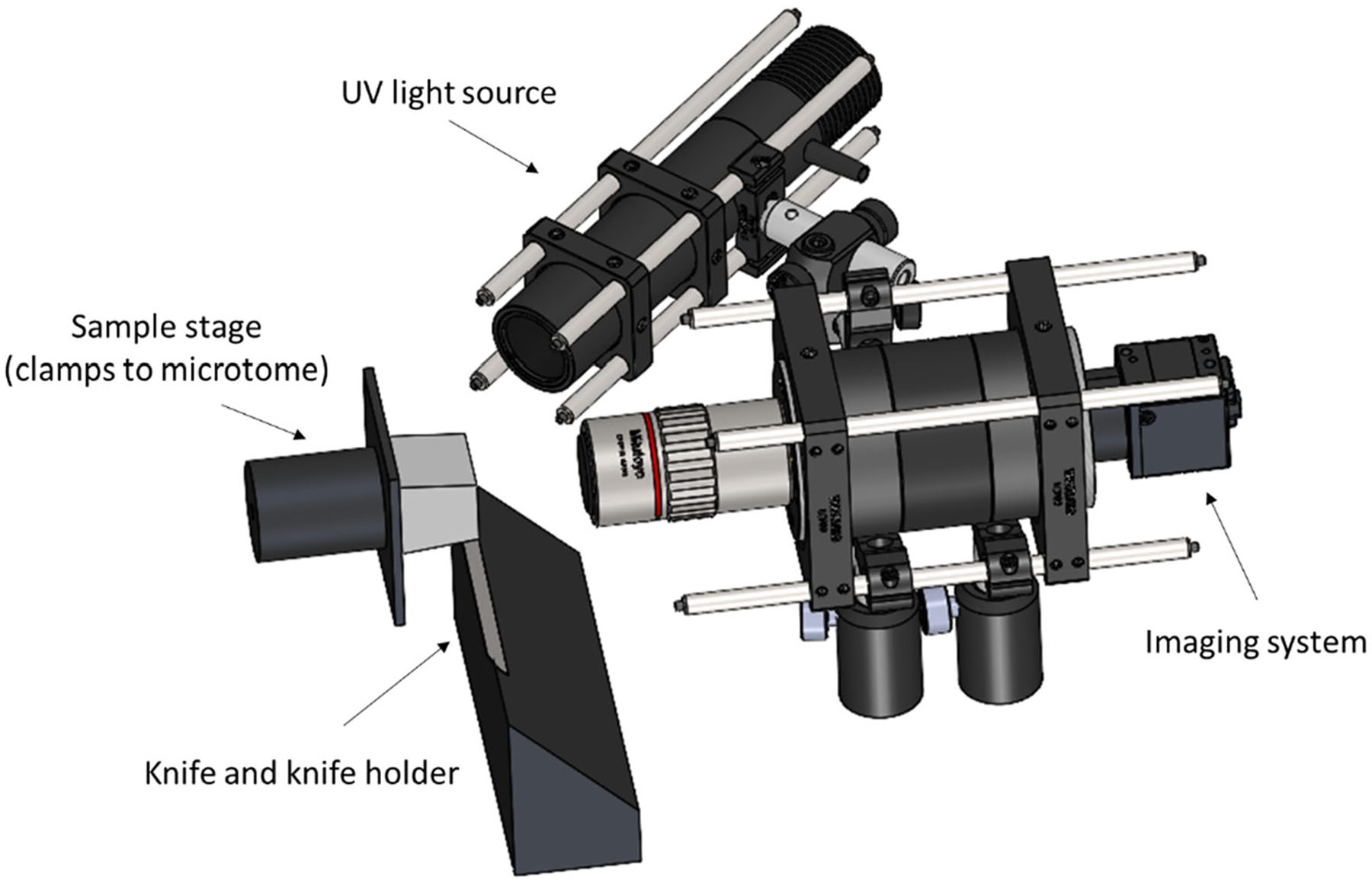
Frozen tissue blocks were sectioned in a modified cryostat unit to permit serial sectioning and imaging. A schematic of our setup is illustrated in Figure 1. A motorized cryostat (Microm HM 550, Thermo Fisher Scientific) capable of producing frozen sections with thickness ranging from 1 to 500 μm was used in our work. Sectioning was performed at 100 μm section thickness with the sample and chamber temperature set to −20 °C. A Hall-effect sensor was incorporated into the cryostat hand-wheel, thereby providing a voltage signal dependent upon the sample’s position in the cutting cycle. Custom software was developed in LabVIEW to monitor this voltage signal continuously and temporarily pause sectioning at the upper reversal point of each cutting cycle. This allowed us to capture an image of the block face after each cut, achieved by sending a trigger signal to the camera. The section and imaging process is completely automated after the user sets the number of section and image cycles to perform.
Figure 1.

Schematic of the 3D-MUSE-cryo imaging system. The frozen sample (illustrated in grey) is attached to the microtome stage and is cut into thin sections by the action of the microtome and the knife cutting edge. We mounted our imaging system along with a UV light source such that the frozen block face can be imaged after each cutting cycle.
Block-face imaging was performed with a 4F imaging system. The imaging system was mounted such that the optical axis was perpendicular to the block surface. The imaging system consists of an infinity corrected, apochromatic objective (Mitutoyo M Plan Apo 2x, 0.05 NA) along with a 100 mm tube lens (Thorlabs TTL100-A), resulting in an effective magnification of 1x. When used with a 1/1.7” CMOS camera (FLIR Blackfly USB3 series), this setup provides a field of view of about 7 × 5 mm in a single tile. As a reference, this field of view is sufficient to cover the entire human vagus nerve, which is commonly around 2–3 mm in diameter. An exposure time of 100 ms was found to be suitable. The objective’s numerical aperture provided sufficient resolution to resolve fascicles which are at least 50 μm in diameter. Depth of field of our imaging system was estimated using the following formula19:
where nbath is the refractive index of the immersion medium (air in our case), λ is the emission wavelength, NA is the numerical aperture of the objective, M is the lateral magnification and e is the pixel size on the camera sensor. Gain ratios for the red and blue color channels (computed w.r.t. the green channel) were held constant during imaging to ensure that the color intensities are uniform over the entire image volume.
2.3. Image processing and visualization
For nerve image datasets, certain image post-processing steps were applied prior to visualization. First, unsharp masking and automatic white balancing operations are applied, as commonly done with conventional MUSE images. Second, images are aligned by an automated stack alignment algorithm in Amira (Thermo Scientific) that uses a least squares quality function in its optimization procedure. Third, a sub-volume consisting of the nerve sample is cropped and fascicles and connective tissue were manually segmented. Labeled volumes were used to create informative surface renderings of fascicle and connective tissues. As an alternative to manual segmentation of the connective tissue, a subset of voxels was selected based on the RGB color information and volume rendered with a custom colormap for direct visualization of the connective tissue and the nerve surface.
3. RESULTS
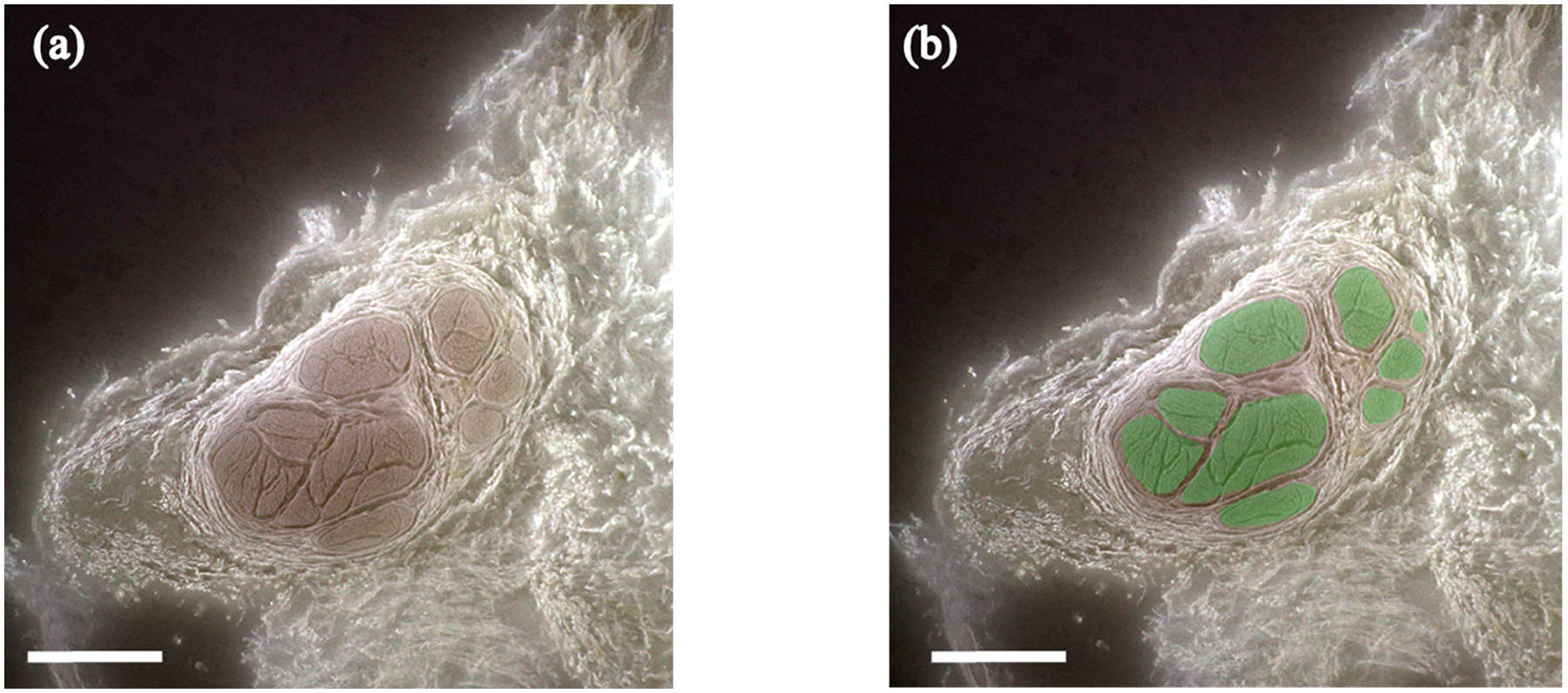
Fixative autofluorescence from UV illumination was found to be sufficient to delineate fascicular structures from surrounding tissue. In this set of experiments, two nerve samples were imaged with 3D-MUSE-cryo to demonstrate feasibility. Depth of focus with our 0.05 NA objective was computed to be around 250 μm using the equation described previously. This value for the depth of focus ensured that the block face remained in focus from one section to the next without significant blurring even in the presence of vibrations from the cryostat compressor. The chosen objective NA offers a theoretical resolution of 6 μm, which was sufficient to identify distinct fascicular regions and reliably perform manual segmentation as shown in Figure 2.
Figure 2.

3D-MUSE-cryo imaging of a fixed cadaver vagus nerve. (a) Frozen block face image, after white balancing and unsharp mask operations are applied. Fascicle structures (brown regions) can be delineated from surrounding tissue in this image. (b) Fascicle regions overlaid in green for the same block face image. Scale bar indicates 1 mm.
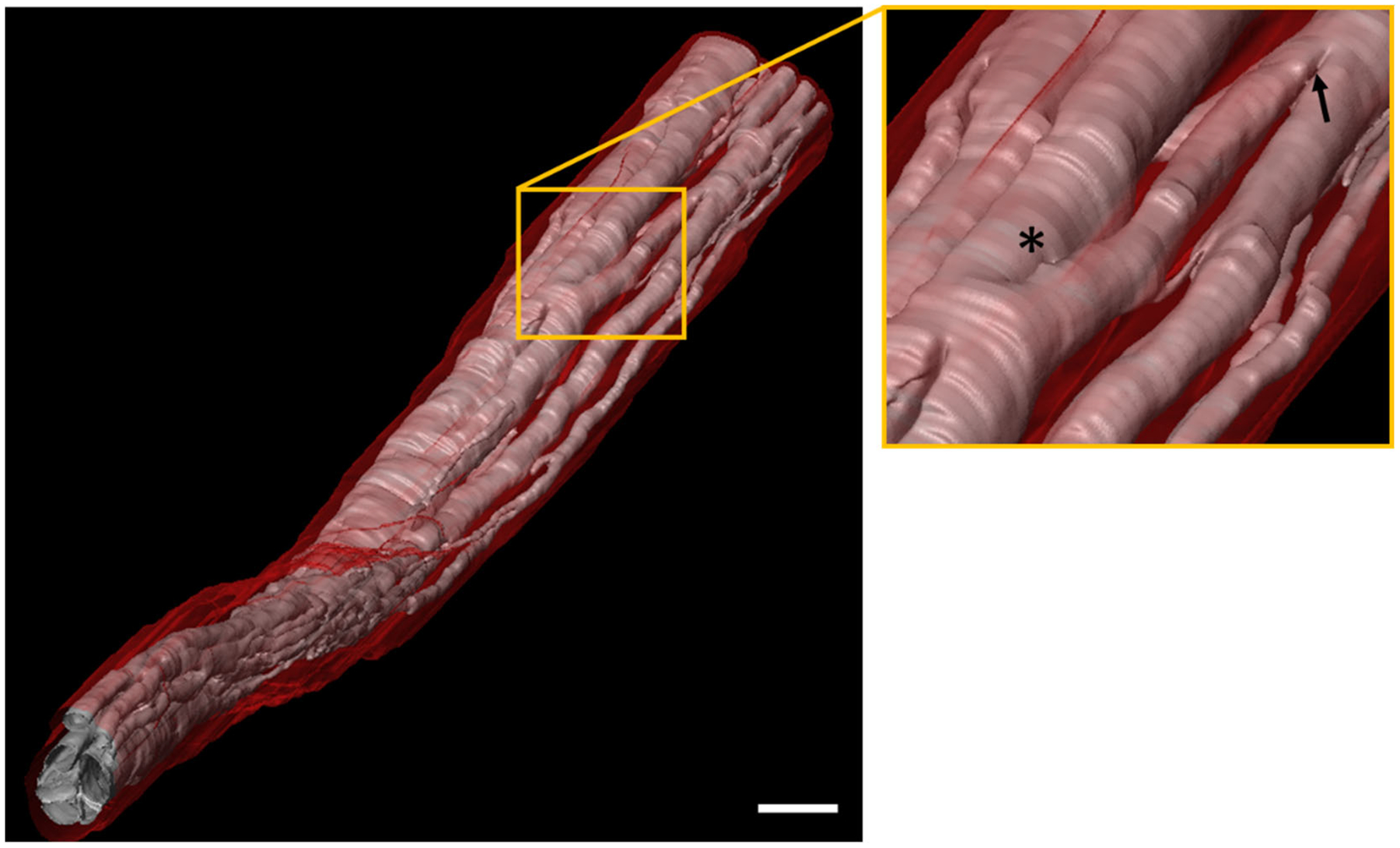
Fascicle branching and merging across the length of the nerve can be readily identified with 3D-MUSE-cryo. In Figure 3, we show 3D surface renderings of fascicles and connective tissue for a 25 mm length vagus nerve sample. The inset illustrates a fascicle split and merge location across the sub-volume. Tracing algorithms can be developed to operate on such labeled volumes to track split and merge events for individual fascicles.
Figure 3.

Surface rendering based visualization of fascicular anatomy of a segment of the human vagus nerve (25 mm in length). Fascicles (pink) are clearly seen along with surrounding connective tissue (red). A close up view of the region in the yellow box is shown on the right. At least one fascicle branching and merging event (indicated by asterisk and arrow respectively) are visible in this region. Scale bar indicates 1 mm.
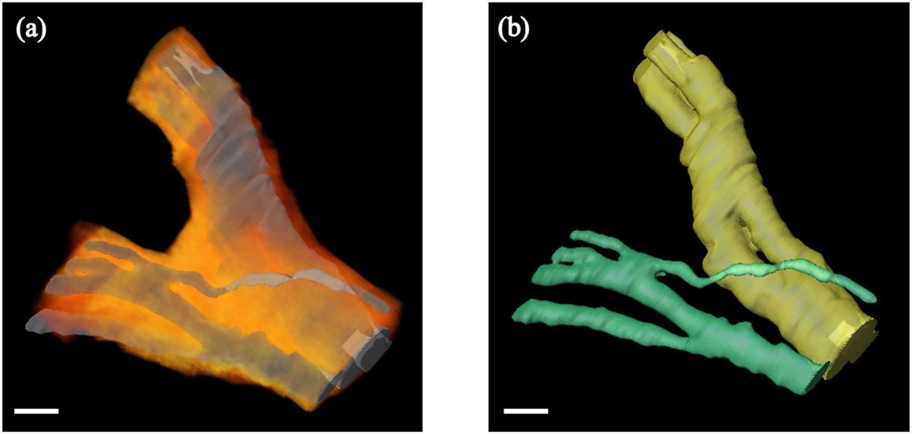
Imaging a nerve sample around a branching region allows us to track fascicles from a branch back to the main trunk. An example of a nerve sample with a branch is shown in Figure 4. After fascicles are identified in both the branch and the main nerve trunk, a 3D connected components algorithm is used to distinguish between the connected fascicle groups.
Figure 4.

3D rendering of the human vagus nerve around a branching point. (a) Fascicle labeled volumes were used to perform surface rendering (shown in gray). We visualize surrounding connective tissue (shown in an orange-red color map) by selecting pixels based on their color channel intensities and performing volume rendering. (b) Fascicles in both the main nerve trunk and the branch can be tracked individually. Fascicle surface rendering from (a) is shown, however, fascicles from the main nerve trunk and the branch are color coded in yellow and green respectively for clarity. Scale bar indicates 1 mm.
4. DISCUSSION
3D-MUSE-cryo is a promising method to image fascicular anatomy of nerve samples, with multiple advantages compared to other common imaging techniques. Since the method relies exclusively on contrast from the fixative, nerve samples can be imaged in situ, without disrupting anatomical orientation and branching. Further, time intensive whole mount tissue staining methods are not necessary, simplifying the sample preparation process. With a section and imaging method such as cryo-imaging, constraints on sample size and resolution present in other imaging methods such as micro-CT and light sheet microscopy are considerably reduced. This allows us to image large volumes of tissue without any gaps in the final volume data. For example, if a research cryostat is employed with our technique, samples as large as 25 × 11 × 5 cm. can be imaged at a time. This is especially important in the context of the vagus nerve, since it is known to be a long, wandering nerve in the human body, extending from the brainstem through the neck down to the thorax and abdomen.
Our preliminary datasets will inform large scale studies of nerve anatomy in the future. Imaging multiple samples from the VNS surgical window can help identify the potential range of variation in fascicle count and branching patterns between individuals. This information can be useful in further elucidating the cause of varied treatment outcomes and off-target effects with VNS therapy. If vagus nerve samples are imaged with their branches intact, such datasets can be used to trace individual fascicles under the electrode and “map” them to effector organs. We will combine our datasets with deep learning based segmentation algorithms in the future, enabling us to automatically create mesh models that will serve as accurate input for computational models of nerve stimulation.
ACKNOWLEDGEMENTS
This work was funded by the National Institutes of Health (NIH)/National Institute of Biomedical Imaging and Bioengineering (NIBIB) #R01EB028635.
REFERENCES
- [1].Yang J, and Phi JH, “The Present and Future of Vagus Nerve Stimulation,” Journal of Korean Neurosurgical Society 62(3), 344–352 (2019). [DOI] [PMC free article] [PubMed] [Google Scholar]
- [2].Handforth A, DeGiorgio CM, Schachter SC, Uthman BM, Naritoku DK, Tecoma ES, Henry TR, Collins SD, Vaughn BV, et al. , “Vagus nerve stimulation therapy for partial-onset seizures: a randomized active-control trial,” Neurology 51(1), 48–55 (1998). [DOI] [PubMed] [Google Scholar]
- [3].“A randomized controlled trial of chronic vagus nerve stimulation for treatment of medically intractable seizures. The Vagus Nerve Stimulation Study Group,” Neurology 45(2), 224–230 (1995). [DOI] [PubMed] [Google Scholar]
- [4].Eljamel S, [Mechanism of Action and Overview of Vagus Nerve Stimulation Technology], in Neurostimulation, John Wiley & Sons, Ltd, 109–120 (2013). [Google Scholar]
- [5].Nicolai EN, Settell ML, Knudsen BE, McConico AL, Gosink BA, Trevathan JK, Baumgart IW, Ross EK, Pelot NA, et al. , “Sources of Off-Target Effects of Vagus Nerve Stimulation Using the Helical Clinical Lead in Domestic Pigs,” bioRxiv2020.01.15.907246 (2020). [DOI] [PMC free article] [PubMed] [Google Scholar]
- [6].Boretius T, Badia J, Pascual-Font A, Schuettler M, Navarro X, Yoshida K, and Stieglitz T, “A transverse intrafascicular multichannel electrode (TIME) to interface with the peripheral nerve,” Biosensors and Bioelectronics 26(1), 62–69 (2010). [DOI] [PubMed] [Google Scholar]
- [7].Larson CE, and Meng E, “A review for the peripheral nerve interface designer,” Journal of Neuroscience Methods 332, 108523 (2020). [DOI] [PubMed] [Google Scholar]
- [8].Musselman ED, Pelot NA, Cariello JE, Goldhagen GB, and Grill WM, “SPARC: Biophysical Modeling of Vagus Nerve Stimulation for Translational Scaling of Stimulation Parameters Across Species,” The FASEB Journal 34(S1), 1–1 (2020). [Google Scholar]
- [9].Thompson N, Ravagli E, Mastitskaya S, Iacoviello F, Aristovich K, Perkins J, Shearing PR, and Holder D, “MicroCT optimisation for imaging fascicular anatomy in peripheral nerves,” Journal of Neuroscience Methods 338, 108652 (2020). [DOI] [PMC free article] [PubMed] [Google Scholar]
- [10].Yan L, Guo Y, Qi J, Zhu Q, Gu L, Zheng C, Lin T, Lu Y, Zeng Z, et al. , “Iodine and freeze-drying enhanced high-resolution MicroCT imaging for reconstructing 3D intraneural topography of human peripheral nerve fascicles,” Journal of Neuroscience Methods 287, 58–67 (2017). [DOI] [PubMed] [Google Scholar]
- [11].Liu A, Xiao W, Li R, Liu L, and Chen L, “Comparison of optical projection tomography and light-sheet fluorescence microscopy,” Journal of Microscopy 275(1), 3–10 (2019). [DOI] [PubMed] [Google Scholar]
- [12].Jung Y, Ng JH, Keating CP, Senthil-Kumar P, Zhao J, Randolph MA, Winograd JM, and Evans CL, “Comprehensive Evaluation of Peripheral Nerve Regeneration in the Acute Healing Phase Using Tissue Clearing and Optical Microscopy in a Rodent Model,” PLoS ONE 9(4), (2014). [DOI] [PMC free article] [PubMed] [Google Scholar]
- [13].Helmers SL, Begnaud J, Cowley A, Corwin HM, Edwards JC, Holder DL, Kostov H, Larsson PG, Levisohn PM, et al. , “Application of a computational model of vagus nerve stimulation,” Acta Neurologica Scandinavica 126(5), 336–343 (2012). [DOI] [PubMed] [Google Scholar]
- [14].Pelot NA, Behrend CE, and Grill WM, “On the parameters used in finite element modeling of compound peripheral nerves,” Journal of Neural Engineering 16(1), 016007 (2019). [DOI] [PMC free article] [PubMed] [Google Scholar]
- [15].Fereidouni F, Harmany ZT, Tian M, Todd A, Kintner JA, McPherson JD, Borowsky AD, Bishop J, Lechpammer M, et al. , “Microscopy with ultraviolet surface excitation for rapid slide-free histology,” Nature Biomedical Engineering 1(12), 957–966 (2017). [DOI] [PMC free article] [PubMed] [Google Scholar]
- [16].Roy D, Steyer GJ, Gargesha M, Stone ME, and Wilson DL, “3D Cryo-Imaging: A Very High-Resolution View of the Whole Mouse,” Anatomical record (Hoboken, N.J. : 2007) 292(3), 342–351 (2009). [DOI] [PMC free article] [PubMed] [Google Scholar]
- [17].Guo J, Artur C, Eriksen JL, and Mayerich D, “Three-Dimensional Microscopy by Milling with Ultraviolet Excitation,” Scientific Reports 9(1), 14578 (2019). [DOI] [PMC free article] [PubMed] [Google Scholar]
- [18].Meng H, Janssen PML, Grange RW, Yang L, Beggs AH, Swanson LC, Cossette SA, Frase A, Childers MK, et al. , “Tissue Triage and Freezing for Models of Skeletal Muscle Disease,” JoVE (Journal of Visualized Experiments)(89), e51586 (2014). [DOI] [PMC free article] [PubMed] [Google Scholar]
- [19].Inoué S, and Spring K, [Video Microscopy: The Fundamentals], 2nd ed., Springer US: (1997). [Google Scholar]


