Abstract
A drive waveform, which needs to be optimized with ink’s fluid properties, is critical to reliable inkjet printing. A generally adopted rule of thumb for its design is mostly dependent on time-consuming and repetitive manual manipulation of its parameters. This work presents a closed-loop machine learning approach to designing an optimal drive waveform for satellite-free inkjet printing at a target velocity. Each of the representative 11 model inks with different fluid properties was ink-jetted with 1100 distinct waveform designs. The high-speed images of their jetting behaviors were acquired and the big datasets of the resulting drop formation and velocity were extracted from the jetting images. Five machine learning models were examined and compared to predict the characteristics of jetting behavior. Among a variety of machine learning models, Multi-layer Perceptron affords the highest prediction accuracy. A closed-loop prediction algorithm that determined the optimal set of waveform parameters for satellite-free drop formation at a target velocity and employed the most superior learning model was established. The proposed method was confirmed through the printing of an unknown model ink with a recommended waveform.
Subject terms: Mechanical engineering, Materials science
Introduction
Drop-on-demand inkjet printing has been widely embraced as a versatile production technology for both small and large formats of graphical and text printing1. As a maskless, non-contact patterning method, this additive manufacturing technology is increasingly being considered a crucial technology for new applications, such as next-generation sensors, circuits, displays, and biological tissues2–6. Unlike other printing processes that produce printed patterns by the transfer of ink from pre-defined master patterns7–9, inkjet printing builds up patterns directly on a substrate by depositing tiny drops of functional inks that contain a wide range of functional components such as metal nanoparticles, conducting polymers, or biological materials. A digitally controlled nozzle produces a series of drops with a diameter of typically 10–100 μm. As the name implies, a piezoelectric inkjet printhead uses a piezoelectric actuator to convert applied electrical energy into mechanical deformation of an ink chamber10. The displacement of the chamber wall controlled by a drive waveform produces the pressure required for a drop to form and eject from the nozzle. Many of the inkjet printing applications necessitate a reliable jetting behavior of functional ink, which is mainly determined by the ink fluid characteristics and drive waveform design11–14.
The ink-jetting process of fluids involves a variety of free surface deformation. Inertia, capillary force, and viscous dissipation are generally used to govern the generation of inkjet drops15. These phenomena can be characterized by dimensionless parametric groups such as Reynolds number (Re), Weber number (We), and Bond number (Bo)
| 1 |
| 2 |
| 3 |
where ρ is the fluid density, η represents the shear viscosity, γ is the surface tension, D is the drop diameter, and v denotes the drop velocity. The Re represents the balance between inertial force and viscous force, and the Weber number represents the ratio of inertial force to capillary force. The effect of gravity is characterized by the Bond number, which can be neglected in most cases for micron-sized drops. The ratio between and 1/2, the inverse of the Ohnesorge number, relates the viscous forces to surface tension forces. Often defined as the Z number, it is used to predict the jetting behavior of drops from Drop-on-Demand (DoD) printhead.
| 4 |
It is widely assumed that Z is required to be in the 1 < Z < 14 range for proper drop formation16,17.
A drive waveform is a set of timed actuator wall movements that generate and propagate acoustic pressure waves within a channel. The drive waveform has a critical role in the operation of the printhead with the ink to be jetted18. Whereas the morphology of a jetted drop is mostly determined by the fluid properties, the incorrect waveform can still lead to unsatisfactory jetting with undesirable satellite formation or even non-jetting. A trapezoidal single-pulse waveform, comprised of the pulse rise, hold, and fall phases, is commonly used to drive the piezoelectric transducer. A widely adopted rule of thumb to optimize a waveform is to scan a range of hold times of the trapezoidal waveform with the predetermined rise and fall times and monitor drop formation19. The optimum is defined here as the highest drop velocity for a given voltage amplitude20–22. New methods have recently been proposed to design customized waveforms for satellite-free jetting. Kwon described a waveform design approach based on monitoring the motion of ink’s meniscus at the nozzle11. His algorithm determined the optimal dwell time by identifying the meniscus location using a charge-coupled device (CCD) camera and strobe LEDs. Xiao et al. designed a unipolar trapezoidal waveform through a combination of laser Doppler vibration testing and numerical simulation23. They first determined rise and fall times by the step response time of the piezoelectric actuated vibration plate and then optimized a dwell time by simulating the velocity wave induced by a rising or falling voltage pulse. The design of a multipulse waveform has recently been presented as a means of reducing the length of ligament or satellite drops24. Hur’s team utilized the lumped element model of a recirculating piezoelectric inkjet printhead to improve bipolar waveforms, demonstrating that a bipolar waveform with a second pulse voltage of 1/3 than that of the first could suppress residual vibrations within the printhead channel25. Despite the development in waveform design methodologies, the knowledge of wave propagation and drop formation is limited, and waveform optimization still requires time-consuming and repetitive waveform parameter modifications, while monitoring obtained jetting images. In addition, the previous experimental studies on the design of an optimal waveform were conducted with one or more limited number of inks for a given printhead26, but it is difficult to apply the proposed waveforms to other ink systems with diverse fluid characteristics.
Meanwhile, smart manufacturing technology has incorporated artificial intelligence (AI) into many different areas of the production process, such as optimization, control, and troubleshooting27–29. Machine learning methods are now being applied in the inkjet printing process. Wu and Xu utilized ensemble learning techniques to design data-driven models to predict drop velocity and volume30. Ogunsany et al. presented a vision-based approach for in-situ monitoring of drop formation31. They classified the state of the jetting behavior from analyzed captured image data using a back-propagation artificial neural network method. Huang and his colleagues proposed an unsupervised learning framework for video data of jetting process to better understand the drop flow pattern and its underlying mechanism32. They demonstrated that a deep recurrent neural network could learn the drop motion at the nozzle and anticipate drop evolution behavior. However, no framework has been devised by any AI approach to recommend drive waveforms in high-quality inkjet printing of a wide range of printable inks.
This study proposes a closed-loop machine learning algorithm for designing an optimal drive waveform for reliable satellite-free inkjet printing. Representative 11 model inks whose Z numbers are between 1 and 50 were ink-jetted to collect the drop formation and velocity dataset. For each ink, 1100 distinct designs of waveforms were applied to a printhead, and its jetting images were obtained using a high-speed imaging technique. Five machine learning models were utilized to predict the characteristics of the jetting behavior, and their performances were compared to determine the most suitable. Following the development of a predicted model, we established a closed-loop algorithm for recognizing the optimal set of waveform parameters for a satellite-free drop formation. Finally, our proposed method was validated by printing an unknown ink with a recommended waveform at a target velocity.
Materials and methods
Inkjet printing system and process
A home-built inkjet apparatus was employed for this experiment. The system comprised a piezoelectric inkjet nozzle with a diameter of 40 μm (MJ-ATP-01-040 DLC, MicroFab Technologies), a waveform driver (JetDrive, MicroFab Technologies), a nano-pulsed flashlight source (NP-1A, SUGAWARA Laboratories Inc), a CCD camera (avA1000-100gm, Basler) with a high magnification zoom lens (Zoom 6000 Lens System, Navitar), and the 5 × objective lenses (Infinity Corrected Long Working Distance Objective, Mitutoyo). The inkjet nozzle belongs to a squeeze-mode design where a piezo transducer wrapped the outside of a glass capillary tube. The inkjet nozzle pushes out the liquid when receiving the trigger pulse at a jetting frequency of 10 Hz. Based on single-flash high-speed imaging, all jetting images were obtained by the ultra-short pulse flashlight and the CCD camera. The drop watcher system employs a stroboscopic principle to capture the jetting image. The strobe trigger delay time can be adjusted in 1 μs increments. The very short flashlight with a duration of 180 ns avoided significant motion blurring. These components were electrically synchronized and controlled by an embedded controller (cRIO-9035 and NI-9401, National Instruments).
Model inks
Deionized water, ethylene glycol, glycerol, and their different mixtures were used as model inks. Information on the fluid properties of those inks is presented in Table 1. Their shear viscosities were measured using a cone-plate viscometer (DV2T, Brookfield) at shear rates of 100–1000 s−1. All inks were Newtonian fluids since the viscosity remained constant in the measured range. Equilibrium surface tension was evaluated with a bubble pressure tensiometer (Proline t15, SITA Lab Solution). Each ink sample was filtered with a 0.45 μm hydrophilic nylon membrane before jetting.
Table 1.
Summary of fluid properties for each ink, together with dimensionless number Z.
| Ink No | Composition (volume fraction) | Density (kg m−3) | Viscosity (mPa s) | Surface tension (mNm−1) | Z | Training | ||
|---|---|---|---|---|---|---|---|---|
| Deionized water | Ethylene glycol | Glycerol | ||||||
| 1 | 100 | 0 | 0 | 998.4 | 1.000 | 71.6 | 53.6 | Used |
| 2 | 90 | 0 | 10 | 1037.0 | 1.613 | 69.3 | 33.2 | Used |
| 3 | 80 | 0 | 20 | 1066.5 | 1.843 | 68.4 | 29.3 | Used |
| 4 | 70 | 0 | 30 | 1093.2 | 2.773 | 67.3 | 19.5 | Used |
| 5 | 60 | 0 | 40 | 1126.3 | 4.140 | 66.5 | 13.2 | Used |
| 6 | 90 | 10 | 0 | 1036.7 | 1.223 | 67.0 | 43.1 | Used |
| 7 | 70 | 30 | 0 | 1043.3 | 1.990 | 61.3 | 25.4 | Used |
| 8 | 40 | 60 | 0 | 1046.7 | 4.520 | 52.3 | 10.5 | Used |
| 9 | 30 | 70 | 0 | 1094.4 | 5.940 | 50.1 | 7.88 | Used |
| 10 | 20 | 80 | 0 | 1106.8 | 8.883 | 49.3 | 5.26 | Used |
| 11 | 0 | 100 | 0 | 1113.5 | 16.38 | 45.3 | 2.74 | Used |
| 12 | 50 | 50 | 0 | 1071.1 | 3.450 | 56.4 | 14.3 | Unused |
Jetting data collection
Each ink was printed with 1100 different shapes of drive waveforms whose parameters such as voltage, rise, dwell and fall time were randomly selected in the range in Table 2, and their jet formation data were produced. The waveform is a trapezoidal pulse comprising driving voltage as well as rise, dwell, and fall times. A LabVIEW™ program was written to repeat the waveform setting–jetting–imaging sequence with increasing flash delay times to capture a series of drop formation images automatically. The delay times were adjusted from 40 to 400 μs with a 5 μs interval. A total of 883,000 jetting images were acquired and stored for the application of the machine learning models. The NI Vision Development Module was used to improve image quality, identify jets and drops, and extract quantitative information, including the number of the produced drops and their velocities. The drops were obtained by counting the main and satellite drops during travelling. The positions of the main drop at different trigger times were recorded and used to calculate the drop velocity.
Table 2.
Ranges of each parameter in waveform.
| Parameters of waveform | Low level | High level |
|---|---|---|
| Voltage (V) | 10 | 80 |
| Rise time (μs) | 2 | 40 |
| Dwell time (μs) | 2 | 60 |
| Fall time (μs) | 2 | 40 |
Machine learning models
Five machine learning algorithms, such as Support Vector Machine (SVM)33, k-Nearest Neighbor (kNN)34, Random Forests (RFs)35, Extreme Gradient Boosting (XGBoost)36, and Multi-layer Perceptron (MLP)37, were implemented to predict drop velocity and formation in this work. All models were programmed using the python scikit-learn package with XGBoost library. We employed the receiver operating characteristic (ROC) curve38 and precision-recall (PR) curve39 to evaluate the predictive ability of the learning models. When evaluating the performance of a machine learning model, the ROC curve demonstrates diagnostic ability, and the PR curve summarizes the trade-off between the true positive rate and the positive predictive value for the learning model from diverse probability thresholds for classification.
Results
Overall workflow of the machine learning
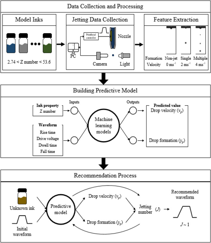
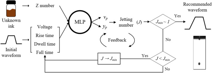
Figure 1 shows the machine learning process for the recommendation of a waveform for satellites-free jetting behavior. The process is comprised of collecting jetting images, building a predictive model, and finding an optimal waveform for reliable single drop jetting. Initially, we collected high-speed jetting images on various fluid properties of inks with different shapes of actuation waveforms, which were employed to extract jetting morphologies and velocity. We categorized jetting morphologies into three regimes of non-jetting (designated as class 0), satellite-free single drop formation (class 1), and multiple drop formation (class 2). The drop formation of jetting behavior and velocity of jets under given conditions were examined from the obtained high-speed images. We then employed five distinct machine learning models, such as Support Vector Machine (SVM), k-Nearest Neighbor (kNN), Random Forests (RFs), Multi-layer Perceptron (MLP), and Extreme Gradient Boosting (XGBoost), and compared their performances to determine the outstanding model for this study. After constructing a predictive model, we established a closed-loop algorithm, which identifies an optimal waveform based on the predictive model. We confirmed that the recommendation stage successfully obtained the optimal waveform of an unknown ink by using the predictive model. Finally, we verified the model using an unknown ink.
Figure 1.
Schematic representation of the working flow for designing an optimized inkjet drive waveform using machine learning models.
Jetting data collection for various inks and waveforms
To collect jetting data and determine how modifying fluid properties of ink and a design of a drive waveform affected jetting behavior, we inkjet-printed 11 different model inks with a different Z number ranging from 2 to 53 by blending deionized water, ethylene glycol, and glycerol. Each ink was ejected with our home-built inkjet system integrated with a high-speed imaging apparatus considering rapid single-flash photography. The rise/fall, dwell time and peak drive voltage of the analog trapezoidal driving pulse were adjusted between 2 and 40 μs, 2 and 60 μs, and 10 and 80 V, respectively. Consequently, each ink was ejected with a total of 1100 distinctly designed jetting waveforms, and their jetting behaviors were recorded with 73 high-speed images for each waveform. The images were used to extract jetting regime and velocity for machine learning.
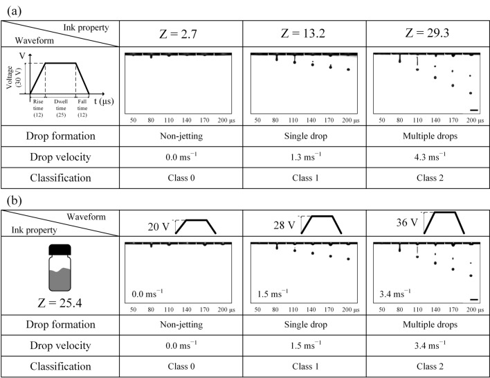
Images of jetting morphologies depending on Z numbers and waveform design are shown in Fig. 2. The increase in Z numbers resulted in various jetting morphologies. For example, Fig. 2a indicates that no drops were generated at a Z number of 2.7, and the single drop formation was achieved by increasing the Z number to 13.2. Further alteration in fluid properties for a higher Z number of 29.3 led to the formation of the main drop accompanied by an unwanted satellite. The waveform remained the same during the experiments. We then examined the influence of the waveform design on jetting behavior for a given ink with a Z value of 25.4. As seen in Fig. 2b, 20 V amplitude of a trapezoidal waveform did not drive an ink drop out of the nozzle; however, an increase to 28 V with rise/fall and dwell times unchanged led to a desirable single main drop. However, satellites were formed for further increased drive voltage.
Figure 2.
The influence of waveform design and ink property on drop formation and drop velocity. (a) Ink property changes with a waveform unchanged. (b) Amplitude of a waveform increased for a model ink. Scale bar: 100 μm.
Predictive model by machine learning
After the collected vision data and their analyses were established, we first identified a total of 5 inputs that influence drop formation and velocity. The drop formation was categorized into three classes based on the number of drops. Class “0” indicates no drop formation, class “1” single drop formation, and class “2” satellites formation. The inputs indicate the ink properties represented by the Z number and the waveform consisted of voltage amplitude, rise, dwell, and fall times. A set of five supervised learning models, including SVM, kNN, RFs, MLP, and XGBoost, were trained by the datasets. To validate the models and decrease the risk of overfitting, the dataset was divided into a training set (60%), a validation set (20%), and a test set (20%).
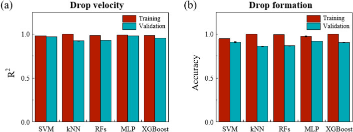
The hyper-parameters of the learning model are summarized in Table 3; the values are tunned based on the performance on the validation set. We evaluated their performance in terms of drop velocity and drop formation. The coefficient of determination (R2) for regression models was examined to predict drop velocity. Fig. 3a illustrates that all of the five machine learning models can be predicted with a high R2 of > 90%. The overall classification performances of SVM, kNN, RFs, MLP, and XGBoost were evaluated by the accuracy as displayed in Fig. 3b. The accuracy values were 0.92, 0.91, 0.86, 0.91, and 0.87 for MLP, SVM, kNN, XGBoost, and RFs, respectively. Among these models, the MLP, SVM, and XGBoost models outperform kNN and RFs, with high prediction accuracy and no significant overfitting in both outcomes.
Table 3.
Summary of important hyper-parameters of machine learning models.
| Learning model | Hyper-parameters | |
|---|---|---|
| Regression | Classification | |
| SVM | C = 10, gamma = 0.3 | C = 10, gamma = 0.5 |
| kNN | k = 10 | k = 20 |
| RFs | Max_depth = 20 | Max_depth = 20 |
| MLP |
1st layer size = 200 2nd layer size = 100 |
1st layer size = 100 2nd layer size = 100 |
| XGBoost | Max_depth = 5 |
Subsample = 0.7 Min_child_weight = 20 |
Figure 3.
Performance evaluation of 5 machine learning models in predicting drop velocity and drop formation. (a) coefficient of determination of predicting drop velocity (b) accuracy of predicting drop formation. SVM, Support Vector Machine; kNN, k-nearest neighbors; RFs, random forests; MLP, Multi-layer Perceptron; XGBoost, extreme gradient boosting.
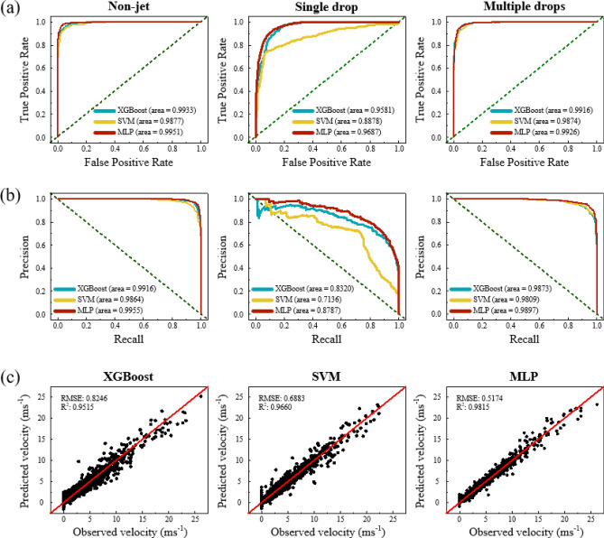
Three preferable models, such as SVM, XGBoost, and the MLP were further compared in detail. During the classification challenge, we constructed receiver operating characteristic (ROC) curves to evaluate the prediction performance of the models. The ROC curve displays the trade-off between the true positive rate and the false positive rate as shown in Fig. 4a. It took the uncertainty of each prediction into account. The deviation of the curve toward the upper left corner from the random guess baseline that is displayed to the green dash line in Fig. 4a indicated higher prediction accuracy. MLP demonstrates the highest deviated ROC curve compared with those of SVM and XGBoost of each class. MLP also reveals the highest value of the area under the ROC curve (AUC), which is equivalent to the probability that the classifier will rank as a randomly chosen positive instance higher than a randomly chosen negative instance in comparison with SVM and XGBoost. The AUC value of MLP was particularly significantly higher than other learning models in class “1.” The overall classification performance of MLP, SVM, and XGBoost was evaluated through the precision-recall (PR) curves as an additional indicator. In contrast to the ROC curve, the more the deviation of a PR curve toward the top right corner from the randomly guessing baseline indicates that a machine learning model achieves higher prediction accuracy. MLP also delivered high predictive performance, as presented in Fig. 4b. MLP obtained a precision of 0.84 at the recall of 0.73 in class “1,” which is substantially higher than those of SVM and XGBoost. In the regression problem, most algorithms showed useful agreement between the observed and predicted velocities as shown in Fig. 4c. MLP also provided the highest R2 of 0.9815 and the lowest root mean square error of 0.5174. We discovered a strong predictive model, which suggests that the MLP model would be most suitable for predicting drop velocities and drop formation.
Figure 4.
(a) Receiver operating characteristic curve and (b) precision-recall curve of predicting drop formation applying the test set in SVM, XGBoost, and MLP models. (c) Comparison of observed and predicted drop velocity using XGBoost, SVM, and MLP in the test set. The green dash line indicates the randomly guessing baseline.
A closed-loop AI algorithm for identifying the optimal waveform
Having evaluated the performances of representative machine learning models, we chose the MLP model to build an optimization algorithm for identifying the optimal waveform. The MLP model deployed initially cannot provide any opportunity for improvement. Therefore, we have built a closed-loop AI algorithm, the waveform design generated by which can be continuously optimized as machine learning improves with data and experience. The algorithm corresponding to the closed-loop waveform optimization is outlined in Fig. 5. The algorithm is performed in two phases. In the first phase, the input layer of the MLP receives the input data for an ink property (Z number) and an initial drive waveform (voltage, rise/dwell/fall times) to be processed. The required task on the prediction of drop velocity (vp) and drop formation (yp) is performed by its output layer. A double hidden layer that is placed in between the input and output layer is the actual computational engine of the model. The second phase is used to actively update the MLP by taking feedback from the outputs.
Figure 5.
Schematic diagram of a waveform recommendation process.
To form a closed-loop for determining an optimal waveform, we define the jetting number (J) as follow:
| 5 |
where vp and vt are MLP-predicted and target drop velocity, respectively, and yp represents the class of drop formation predicted by MLP, and δ denotes a minimal value to avoid divergence. The jetting number consists of the sum of terms reducing the error of drop velocity and formation. The former term is the squared prediction error for target drop velocity, which encourages a predicted drop velocity to reach target velocity. The latter term aims to search for a class of single drop formation. The algorithm iterates until the calculated value of J is close to 1, recommending an optimal set of waveform parameters for satellite-free drop formation at a target velocity.
Verification
To verify the proposed method, we prepared an ink with Z = 14.25 that had not been used for training. The target velocity was set to 1.5 ms−1 to calculate the jetting number. In Fig. 6a, the double drops were ejected at the initial waveform (peak voltage = 70 V, rising time = 31 μs, dwell time = 26 μs and falling time = 11 μs). The velocity of the main drop was 2.54 ms−1. After using the proposed method, the waveform factors were adjusted for voltage, rise/dwell/fall times as 66 V, 29 μs, 24 μs, and 13 μs, respectively. In Fig. 6b, double drops were formed, yet the second drop merged with the main drop at 1.62 ms−1 after an elapsed time of 220 μs. The fall time was increased by 2 μs and the voltage, rise time, and dwell time were reduced by 4 V, 2 μs, and 2 μs, respectively. The parameters of the waveform change according to iteration as displayed in Fig. 7. The change of the waveform occurs, causing the drop velocity to decrease. These findings suggest that MLP recognizes the need to reduce voltage and pulse width to reduce drop velocity.
Figure 6.
(a) Sequence images of drop formation at an initial waveform and (b) an optimized waveform from the proposed method. Scare bar: 100 μm.
Figure 7.
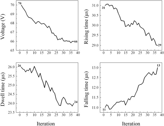
Change of waveform parameters for iteration.
Conclusion
In this study, we introduced a closed-loop machine learning process to recommend the optimal design of a drive waveform for satellite-free inkjet printing. We created and collected the big datasets of drop formation and velocity with 11 representative inks with different fluid properties and 1100 distinct waveform designs. We concluded that MLP achieved the best prediction of drop formation and drop velocity among the five representative machine learning models tested. We developed the closed-loop algorithm to recommend the optimal waveform with the Jetting number. The model was verified with an unknown ink for target drop velocity of 1.5 ms−1 and single drop formation. We anticipate that our approach can be applied to a wide range of Newtonian inks and industrial printheads. Future work will establish an advanced machine learning process with non-Newtonian inks and bipolar waveform designs.
Acknowledgements
This work was supported by the Korea Innovation Foundation (INNOPOLIS) grant (2020-DD-UP-0278) and by the Technology Innovation Program (No. 20010464) funded by the Ministry of Trade, Industry & Energy (MOTIE, Korea). SK thanks Dr. Jimin Kwon for useful discussion.
Author contributions
S.K. and S.J. conceived the project. S.K. performed all the experiments and analyzed the data. M.C. contributed to design and analyze machine learning models. All authors discussed and wrote the manuscript.
Competing interests
The authors declare no competing interests.
Footnotes
Publisher's note
Springer Nature remains neutral with regard to jurisdictional claims in published maps and institutional affiliations.
Contributor Information
Minsu Cho, Email: mscho@postech.ac.kr.
Sungjune Jung, Email: sjjung@postech.ac.kr.
References
- 1.Singh M, Haverinen HM, Dhagat P, Jabbour GE. Inkjet printing-process and its applications. Adv. Mater. 2010;22:673–685. doi: 10.1002/adma.200901141. [DOI] [PubMed] [Google Scholar]
- 2.Kwon J, et al. Three-dimensional monolithic integration in flexible printed organic transistors. Nat. Commun. 2019;10:54. doi: 10.1038/s41467-018-07904-5. [DOI] [PMC free article] [PubMed] [Google Scholar]
- 3.Park JA, Lee H, Park S, Jung S. Self-organization of fibroblast-laden 3D collagen microstructures from inkjet-printed cell patterns. Adv. Biosyst. 2020;4:1900280. doi: 10.1002/adbi.201900280. [DOI] [PubMed] [Google Scholar]
- 4.Baek S, Bae GY, Kwon J, Cho K, Jung S. Flexible pressure-sensitive contact transistors operating in the subthreshold regime. ACS Appl. Mater. Interfaces. 2019;11:31111–31118. doi: 10.1021/acsami.9b09636. [DOI] [PubMed] [Google Scholar]
- 5.Kwon J, Matsui H, Kim W, Tokito S, Jung S. Static and dynamic response comparison of printed, single- and dual-gate 3-D complementary organic TFT inverters. IEEE Electron Device Lett. 2019;40:1277–1280. doi: 10.1109/LED.2019.2922296. [DOI] [Google Scholar]
- 6.Kang D, et al. All-inkjet-printed 3D alveolar barrier model with physiologically relevant microarchitecture. Adv. Sci. 2021;8:2004990. doi: 10.1002/advs.202004990. [DOI] [PMC free article] [PubMed] [Google Scholar]
- 7.Meitl MA, et al. Transfer printing by kinetic control of adhesion to an elastomeric stamp. Nat. Mater. 2006;5:33–38. doi: 10.1038/nmat1532. [DOI] [Google Scholar]
- 8.Li M, Li Y-T, Li D-W, Long Y-T. Recent developments and applications of screen-printed electrodes in environmental assays—A review. Anal. Chim. Acta. 2012;734:31–44. doi: 10.1016/j.aca.2012.05.018. [DOI] [PubMed] [Google Scholar]
- 9.Kim W, et al. Flexible and printed organic nonvolatile memory transistor with bilayer polymer dielectrics. Adv. Mater. Technol. 2021;6:2100141. doi: 10.1002/admt.202100141. [DOI] [Google Scholar]
- 10.Wijshoff H. The dynamics of the piezo inkjet printhead operation. Phys. Rep. 2010;491:77–177. doi: 10.1016/j.physrep.2010.03.003. [DOI] [Google Scholar]
- 11.Kwon Kye-Si. Waveform design methods for piezo inkjet dispensers based on measured meniscus motion. J. Microelectromech. Syst. 2009;18:1118–1125. doi: 10.1109/JMEMS.2009.2026465. [DOI] [Google Scholar]
- 12.Kwon K-S, Kim W. A waveform design method for high-speed inkjet printing based on self-sensing measurement. Sens. Actuators A Phys. 2007;140:75–83. doi: 10.1016/j.sna.2007.06.010. [DOI] [Google Scholar]
- 13.Jung S, Hoath SD, Hutchings IM. The role of viscoelasticity in drop impact and spreading for inkjet printing of polymer solution on a wettable surface. Microfluid. Nanofluidics. 2013;14:163–169. doi: 10.1007/s10404-012-1034-3. [DOI] [Google Scholar]
- 14.Vadillo DC, et al. Evaluation of the inkjet fluid’s performance using the “Cambridge Trimaster” filament stretch and break-up device. J. Rheol. (N. Y. N. Y.) 2010;54:261–282. doi: 10.1122/1.3302451. [DOI] [Google Scholar]
- 15.Nayak L, Mohanty S, Nayak SK, Ramadoss A. A review on inkjet printing of nanoparticle inks for flexible electronics. J. Mater. Chem. C. 2019;7:8771–8795. doi: 10.1039/C9TC01630A. [DOI] [Google Scholar]
- 16.Derby B. Inkjet printing of functional and structural materials: fluid property requirements, feature stability, and resolution. Annu. Rev. Mater. Res. 2010;40:395–414. doi: 10.1146/annurev-matsci-070909-104502. [DOI] [Google Scholar]
- 17.Jang D, Kim D, Moon J. Influence of fluid physical properties on ink-jet printability. Langmuir. 2009;25:2629–2635. doi: 10.1021/la900059m. [DOI] [PubMed] [Google Scholar]
- 18.Shin P, Sung J, Lee MH. Control of droplet formation for low viscosity fluid by double waveforms applied to a piezoelectric inkjet nozzle. Microelectron. Reliab. 2011;51:797–804. doi: 10.1016/j.microrel.2010.11.017. [DOI] [Google Scholar]
- 19.Kwon K-S, et al. Review of digital printing technologies for electronic materials. Flex. Print. Electron. 2020;5:043003. [Google Scholar]
- 20.Kwon K-S. Experimental analysis of waveform effects on satellite and ligament behavior via in situ measurement of the drop-on-demand drop formation curve and the instantaneous jetting speed curve. J. Micromech. Microeng. 2010;20:115005. doi: 10.1088/0960-1317/20/11/115005. [DOI] [Google Scholar]
- 21.Chang J, Liu Y, Huang B. Effects of dwell time of excitation waveform on meniscus movements for a tubular piezoelectric print-head: experiments and model. J. Micromech. Microeng. 2017;27:075023. doi: 10.1088/1361-6439/aa7040. [DOI] [Google Scholar]
- 22.Shin WJ, Jeong YS, Choi K, Shin WG. The effect of inkjet operating parameters on the size control of aerosol particles. Aerosol. Sci. Technol. 2015;49:1256–1262. doi: 10.1080/02786826.2015.1115465. [DOI] [Google Scholar]
- 23.Xiao X, et al. A waveform design method for piezoelectric inkjet printhead with Doppler vibration test and numerical simulation. Microelectron. Eng. 2018;196:13–19. doi: 10.1016/j.mee.2018.04.018. [DOI] [Google Scholar]
- 24.Oktavianty O, Kyotani T, Haruyama S, Kaminishi K. New actuation waveform design of DoD inkjet printer for single and multi-drop ejection method. Addit. Manuf. 2019;25:522–531. [Google Scholar]
- 25.Shah MA, et al. Actuating voltage waveform optimization of piezoelectric inkjet printhead for suppression of residual vibrations. Micromachines. 2020;11:900. doi: 10.3390/mi11100900. [DOI] [PMC free article] [PubMed] [Google Scholar]
- 26.Hamad AH, Salman MI, Mian A. Effect of driving waveform on size and velocity of generated droplets of nanosilver ink (Smartink) Manuf. Lett. 2020;24:14–18. doi: 10.1016/j.mfglet.2020.03.001. [DOI] [Google Scholar]
- 27.Jiang, J., Xiong, Y., Zhang, Z. & Rosen, D. W. Machine learning integrated design for additive manufacturing. J. Intell. Manuf., 1-14 (2020).
- 28.Wang J, Ma Y, Zhang L, Gao RX, Wu D. Deep learning for smart manufacturing: Methods and applications. J. Manuf. Syst. 2018;48:144–156. doi: 10.1016/j.jmsy.2018.01.003. [DOI] [Google Scholar]
- 29.Cus F, Balic J. Optimization of cutting process by GA approach. Robot. Comput. Integr. Manuf. 2003;19:113–121. doi: 10.1016/S0736-5845(02)00068-6. [DOI] [Google Scholar]
- 30.Wu D, Xu C. Predictive modeling of droplet formation processes in inkjet-based bioprinting. J. Manuf. Sci. Eng. 2018;140:101007. doi: 10.1115/1.4040619. [DOI] [Google Scholar]
- 31.Ogunsanya M, Isichei J, Parupelli SK, Desai S, Cai Y. In-situ droplet monitoring of inkjet 3D printing process using image analysis and machine learning models. Procedia Manuf. 2021;53:427–434. doi: 10.1016/j.promfg.2021.06.045. [DOI] [Google Scholar]
- 32.Huang J, et al. Unsupervised learning for the droplet evolution prediction and process dynamics understanding in inkjet printing. Addit. Manuf. 2020;35:101197. [Google Scholar]
- 33.Burges CJC. A tutorial on support vector machines for pattern recognition. Data Min. Knowl. Discov. 1998;2:121–167. doi: 10.1023/A:1009715923555. [DOI] [Google Scholar]
- 34.Zhang Z. Introduction to machine learning: k-nearest neighbors. Ann. Transl. Med. 2016;4:218–218. doi: 10.21037/atm.2016.03.37. [DOI] [PMC free article] [PubMed] [Google Scholar]
- 35.Breiman, L. Random Forests. Mach. Learn.45, 5-32 (2001).
- 36.Chen, T. & Guestrin, C. XGBoost: A Scalable Tree Boosting System. In Proceedings of the 22nd ACM SIGKDD International Conference on Knowledge Discovery and Data Mining 785–794 (2016).
- 37.Jain AK, Mao J, Mohiuddin KM. Artificial neural networks: a tutorial. Computer (Long. Beach. Calif.) 1996;29:31–44. [Google Scholar]
- 38.Fawcett T. An introduction to ROC analysis. Pattern Recognit. Lett. 2006;27:861–874. doi: 10.1016/j.patrec.2005.10.010. [DOI] [Google Scholar]
- 39.Davis, J. & Goadrich, M. The relationship between Precision-Recall and ROC curves. In Proceedings of the 23rd international conference on Machine learning 233–240 (2006).


