

Abstract

In this work, using electrochemical active Fe as an ion-exchange element (attack side) and the NaxMnFe(CN)6 slurry with a high solid content (MnHCF) as a template (defensive side), a series of binary hexacyanoferrates are prepared via a simple Mn/Fe ion-exchange process, in which NaxFeFe(CN)6 (FeHCF) and solid solution Nax(FeMn)Fe(CN)6 are concentrated on the shell and the core, respectively. The proportions of the two structures are mainly controlled by the competition between the ion-exchange rate in the bulk material and dissolution-reprecipitation rate. Slowing down the attacking rate, such as the use of a chelating agent complexed with the attacker Fe, is advantageous to form a thermodynamically metastable state with homogeneous distribution of elements since the diffusion of Fe2+ in the solid MnHCF is relatively fast. The shell FeHCF could be adjusted by the dissolution-reprecipitation rate, which is driven by the solubility difference. Adding the chelating agent in the defensive side will promote the dissolution of MnHCF and reprecipitation of FeHCF on the surface. Meanwhile, with the increase of Fe sources, the thickness of the shell FeHCF increases, and correspondingly the content of solid solution decreased due to FeHCF is more stable than solid solutions in thermodynamics. Finally, such a design principle in this case study could also be generalized to other ion-exchange processes. Considering the difference of two components in solubility, the larger difference can make the core/shell structure more clear due to the enhancement of dissolution–reprecipitation route.
1. Introduction
Prussian blue and its analogues (PBAs) with a unique three-dimensional (3D) open framework are promising multifunctional materials in many fields, such as energy storage,1 gas storage,2 stimuli-dependent magnetic,3 and metal-ion immobilization.4 Generally, these materials have a general formula of AxMyFe(CN)6·nH2O, abbreviated as MHCF (A is the alkali cation and M is a divalent or trivalent transition metal), in which 6-fold C coordinated Fe and 6-fold N-coordinated M are connected by CN ligands, forming Fe–CN–M linked open frameworks.
In recent years, the functionalization of PBAs has been more focused on the regulation of transition-metal sites M. First, the kinds of M determine the structure-performance relationship on the whole. When A = Na and M = Mn, Fe, there were two redox sites, contributing capacity as high as 170 mAh/g, different from other cases with only one redox site responsible for sodium extraction and insertion.1 As for hydrogen gas storage, the sorption capacity of hydrogen gas mostly depends on the metal ion.2 Second, for those PBAs sharing the same M lattice site by two or three transition metals, the distribution of M might bring a great variance on the performance. For example, gadolinium ions embedded in Prussian blue nanoparticles with a concentration gradient were demonstrated to facilitate proton relaxivity and magnetic resonance imaging contrast.5 Similarly, a core of (Rb0.5Co[Fe(CN)6]0.8·H2O, RbCoFe) and a shell of (Rb0.2Ni[Cr(CN)6]0.7·H2O, RbNiCr) were successfully designed as photostrictive/piezo-magnetic heterostructures due to confinement effects.6 In addition, the concentration gradient or core/shell structure was usually proposed to inhibit the mechanical degradation of core materials and improve the electrochemical cyclability of cathodes.7 For example, NaxNiyMn1–yFe(CN)6·nH2O particles with concentration gradient, in which the Ni content gradually increased from the interior to the particle surface, were synthesized to retard the mechanical degradation and improve the electrochemical cyclability.8 Therefore, rational design and precise construction of PBAs, in terms of transition metals composition and distribution, is quite necessary to enable specific properties.
To this end, various preparation methods have been explored, of which the commonly used one was the gradient control of the concentrations of the mother solution of MA and MB. In detail, MA solution feedstock was continuously introduced into the MB solution to form a time-dependent MA concentration in the mother solution, thus achieving the MA concentration-gradient crystal growth.8−10 Besides, the one-pot coprecipitation reaction was also a common method to construct high-entropy structures.11−13 For example, the MnHCF coated with a thin epitaxial surface layer of nickel-based Prussian blue was successfully constructed due to unequal affinity for Mn2+ and Ni2+ with sodium citrate.12 However, for these cases, it meets a challenge in practice due to a complicated feeding system or poor productivity. Alternatively, the ion-exchange process is a simple and exclusive method for PBAs to construct structures based on different solubilities of the involved candidates.14−16 For example, a core–shell sodium manganese hexacyanoferrate coated by sodium nickel hexacyanoferrate (PBM@PBN) PBAs was synthesized via a simple solution precipitation and subsequent in situ ion exchange.16 Zhao et al. investigated the Cu/Mn ion-exchange based on MnHCF and found that the ion exchange in a media with low concentrations of Na+ caused a significant loss of Na from the NaMnHCF, while employing a high concentration of Cu2+ can result in an overexchange of Cu for Mn.15 Although these ion-exchange processes seem to work to some extent, there is still a lack of systematic research on the flexible regulation of crystal structures and the general strategy capable for ion exchange process design.
In this case study, Prussian white (NaxMnFe(CN)6, a promising cathode in SIB with high capacity but poor stability) was chosen as a template requiring structure reconstruction essentially;17−19 Fe was chosen as an ion-exchange element since it is electrochemical active and could be a good indicator to reflect the structural composite through charge–discharge curves. We found that the final product of ion-exchange generally tended to form a core–shell structure, where the shell and the core were enriched with NaxFeFe(CN)6 (FeHCF) and Nax(FeMn)Fe(CN)6, respectively. The influence factors of ion-exchange processes were systematically investigated based on the characterizations of the composition and structure by EDS line scan, ICP-MS, and initial charge–discharge curve, revealing the mechanism that determined the product evolution in composition by the competition between ion-exchange and dissolution–reprecipitation proceeding simultaneously. Furthermore, the rational strategy toward the Mn/Ni ion exchange was verified, presenting the potential of the mechanism as guidance.
2. Experimental Section
2.1. Chemicals and Materials
Sodium chloride (NaCl, AR) was purchased from the Sinopharm Chemical Reagent Co., Ltd. Manganese(II) chloride and tetrahydrate (MnCl2·4H2O, ≥98%) were purchased from Sigma-Aldrich. Sodium ferrocyanide (Na4Fe(CN)6, ≥98%) and ethylenediaminetetraacetic acid disodium salt dihydrate (EDTA·2Na, ≥99%) were purchased from Beijing Innochem Co., Ltd. Iron chloride tetrahydrate (FeCl2·4H2O, ≥98%) was purchased from Acros. Trisodium citrate, anhydrous (C6H5Na3O7, ≥99%), and sodium gluconate (C6H11NaO7, ≥99%) were purchased from Tokyo Chemical Industry Co., Ltd. All the chemicals were used without purification.
2.2. Ion-Exchange Process
For the ion-exchange process, the MnHCF slurry was chosen as a template that was prepared via a previous bottom-up approach,19 which contained 1.3 M NaCl that could ensure a sufficient sodium content in the lattice. The pH of the slurry was 6.40. As shown in Figure 1, the ion-exchange process was carried out at 140 °C under 600 rpm stirring and nitrogen atmosphere in a HEL PolyBLOCK reactor system. A 40 mL of MnHCF slurry, denoted as the defensive side, was fed into the reactor directly in advance. The 20 mL of solution containing transition-metal salt, denoted as the attack side, was continuously fed into the reactor at 1 mL/min during experiments. The duration of ion-exchange experiments was 2 h with feeding time included. Then, the powders were collected by centrifugation, washed with deionized (DI) water and ethanol several times, and dried at 80 °C for 24 h. Before electrochemical characterization, the powders were calcinated at 200 °C for 4 h to remove the interstitial water.
Figure 1.

Experimental setup of the ion-exchange process.
2.3. Characterization of Materials
The morphology of the products was observed via transmission electron microscopy (TEM; JEM-2010, 120 kV) and scanning electron microscopy (SEM; HITACHI-SU8010, 15 kV). The X-ray powder diffraction patterns were collected on an X-ray powder diffractometer (D8-Advance) operating at 40 kV and 40 mA using Cu Ka radiation at a scanning rate of 5°/min. The elemental composition of the samples (referring to Na/Mn/Fe) was determined by inductively coupled plasma-optical emission spectroscopy (ICP-OES). In detail, Prussian white was totally dissolved in the hot acid mixture (HCl/HNO3, 3:1) and then diluted 10 times before ICP-OES measurements. Thermogravimetric analysis was performed using a Simultaneous Thermal Analyzer (NETZSCH STA 409 PC/PG) under N2 atmosphere. Fourier transform infrared (FTIR) spectra were measured using a FTIR spectrometer (TENSOR 27, Bruker). The Raman spectra were collected using a HORIBA LabRAM HR Evolution Raman spectrometer, with a 0.325 mW/cm2 helium/neon laser at 532 nm excitation in the range of 1500–2200 cm–1. To compare the Ksp of different transition metals, in situ conductivity measurement (Mettler Toledo, InLab 720) was carried out after the 0.001 mol/L MnCl2, FeCl2, CuCl2, and NiCl2 were rapidly mixed with 0.001 mol/L Na4Fe(CN)6, respectively.
As for the electrochemical analysis, CR2032 coin-type cells were assembled in an argon-filled glovebox using sodium foil and a Whatman GF/D glass fiber as the counter electrode and the separator, respectively. To prepare the working electrodes, the active material powder, super P, Ketjen black, and poly(vinylidene fluoride) binder were mixed at a mass ratio of 70:10:10:10 in N-methyl-2-pyrrolidone solvent. The mass loading of active materials NaFeHCF in the electrode was 1–1.2 mg·cm–2. The electrolyte was 1 M NaPF6 in a mixed solvent of ethylene carbonate (EC)/propylene carbonate (PC) at the volume ratio of 1:1 with 5% vol FEC as additive.
3. Results and Discussion
3.1. Product Characteristics
First of all, we systematically characterized the product after ion-exchange in the Mn/Fe ion-exchange system. As a reference of the ion-exchange process, the attack side contained 0.09 mol/L Fe2+ and 0.18 mol/L Cit-Na, and the defensive side contained strong chelating agent EDTA which was half of Fe2+ in the molar content. The XRD pattern treated by the Rietveld method showed that the product exhibited a monoclinic structure with a = 10.5378 Å, b = 7.4911 Å, c = 7.2817 Å, β = 92.453°, and V = 574.284 Å3 (Figure S1). Compared with the pristine MnHCF, the unit cell volume slightly shrank due to the decrease of parameters a, b, and c. The ICP-OES measurement showed that the overall element ratio of Mn/Fe was 0.31, far lower than that of the pristine MnHCF, 1.03, indicating the Mn was successfully substituted by Fe. The EDS linear scanning was employed to analyze the local composition and distribution of transition metals,9 which also showed the content of Fe was significantly higher than Mn (Figure 2a). As for the distribution of elements, Fe and Mn were homogeneously distributed at the center of particles; within a depth of tens of nanometers from the surface, the ratio of Fe to Mn seemed to be high comparatively. The charge–discharge measurements at the first cycle under 1 C rate were conducted to recognize the structure from electrochemical performance. Figure 2b showed the charging process could be divided into three stages. Stage I was located between 2 and 3.2 V, corresponding to the redox couple of the high-spin Fe2+/3+ coordinated with N. Stage II showed a slope charge curve between 3.4 and 3.8 V, which could be inferred as a solid-solution mechanism during the extraction/insertion of Na ion, that is, Fe and Mn shared the same M position where Fe atoms partially replace the nitrogen-coordinated Mn atoms in the framework.11,20 Stage III was at 4.0–4.2 V, assigned to the redox couple of low-spin Fe2+/3+ coordinated with C. Stages I and III could be both attributed to the formation of FeHCF,21 which contributed half of the total capacity. Noteworthy, the structure after ion exchange exhibited a high capacity of 150 mAh/g at 1 C, almost the same with the MnHCF.19,22 In summary, we inferred that the Fe concentrated on the edge probably existed as the FeHCF, while the homogeneous distribution of Fe and Mn may be the solid solution Nax(MnFe)[Fe(CN)6]y.
Figure 2.

(a) EDS line scans of the particles. (b) Charge–discharge curve of the sample after ion-exchange process.
3.2. Composition Regulation
Since the FeHCF and solid solution Nax(MnFe)[Fe(CN)6]y were two of the main compositions after the ion-exchange process, how to regulate the proportion of them in the final product becomes key to construct various composite structures. In this regard, the attack side and defensive side were investigated separately.
3.2.1. Effect of the Attack Side
First, the concentration of Fe2+ was fixed at 0.06 mol/L in the attack side solution, and a set of various molar ratios of Fe2+ to sodium citrate were selected (1:0, a-1; 1:2, a-2; 1:4, a-3). The pH values in the attack side were 3.40, 5.95, and 6.39 for a-1, a-2, and a-3, respectively. EDS measurements indicated Fe and Mn in the pristine MnHCF were almost consistent along the scanning line (Figure 3a), and for the ion-exchanged samples, the content of Fe was significantly higher than the content of Mn (Figures 3b–d). The difference of various ion-exchange samples was that without the chelating agent, Fe concentration increased more rapidly than Mn concentration at the edge (Figure 3b); instead, with the addition of chelating agent, Fe and Mn were homogeneously distributed thoroughly. Understandably, when Fe2+ was complexed with sodium citrate, the ion-exchange process proceeded at a fairly slow rate and the a-2 and a-3 inclined to form thermodynamically metastable structure, thus resulting in homogeneous distribution of Fe and Mn. The architecture with the enrichment of Fe at the edge could be seen as the kinetic product due to the fast ion-exchange rate. For the overall Fe and Mn content of three ion-exchange samples, ICP measurement was used to analyze the degree of substitution of Mn by Fe. As shown in Figure 4a, with the increase of the molar ratio of sodium citrate to Fe2+ in the attack side, the total Mn/Fe also increased, indicating the substitution of Mn2+ by Fe2+ gradually decreased as the attack rate slowed down. Meanwhile, the Na/(Mn + Fe) still remained around 1, the theoretical value without Na loss. Raman spectra were collected to determine the states of transition-metal ions bonded to CN–. As shown in Figure S2, compared with pristine MnHCF, the main peaks located at about 2130 and 2080 cm–1 shifted to higher wavenumbers with the substitution of Fe, which was in accord with the red shift previously reported.20 Finally, galvanostatic charge/discharge tests at 120 mA/g were performed to recognize the composition quantitatively from the capacity contribution. As shown in Figure 5a, total discharge capacity of a-1 was far behind that of a-2 and a-3. Moreover, for a-1, there were two distinct plateaus between 3.4 and 3.7 V (solid solution reaction) and 3.7 and 3.8 V (high spin Mn3+/Mn2+ redox potential) in stage II and a longer charge plateau over 4.0 V corresponding to the low-spin Fe3+/Fe2+ redox potential of the FeHCF; for a-2 and a-3, there was far less capacity contribution over 4.0 V and showed a voltage slope between 3.4 and 3.8 V. These results indicated that the a-1 sample contained more FeHCF and separate MnHCF (unsubstituted) and a-2 and a-3 samples were dominated by the solid solution because the superior Fe2+ diffusion rate in the solid MnHCF over ion-exchange inhibited by complexation facilitated the formation of the metastable state.
Figure 3.

EDS line scans of the particles prepared with the attack side containing different Cit-Na addition: (a) MnHCF without treatment; (b) Fe2+ (a-1); (c) Fe2+:Cit-Na = 1:2 (a-2); and (d) Fe2+:Cit-Na = 1:4 (a-3).
Figure 4.

(a) (Mn/Fe) and Na/(Mn + Fe) content obtained from ICP-MS. The attack side was Fe2+ complexed with different concentration Cit-Na. (b) (Mn/Fe) content obtained from ICP-MS. The attack side contained different Fe2+ concentration that complexed with Cit-Na at a molar ratio of 1:2.
Figure 5.

Charge–discharge curves of the samples after ion-exchange. (a) The attack side was Fe2+ complexed with different concentration Cit-Na. (b) The attack side contained different Fe2+ concentration.
Next, we fixed the molar ratio of Fe2+ to sodium citrate at 1:2 on the attack side and changed the concentration of Fe2+ and sodium citrate simultaneously. Correspondingly, the samples were denoted as a-4 (0.03 mol/L Fe2+), a-5 (0.06 mol/L Fe2+), a-6 (0.09 mol/L Fe2+), and a-7 (0.12 mol/L Fe2+), respectively. As we could see, with the increase of Fe sources, the overall Mn/Fe content was decreased as expected (Figure 4b). From the EDS linear scanning results (Figure S3), on the edge, the difference between Fe and Mn was gradually increased. This could be attributed to the formation of more FeHCF as the capacity contribution of stages I and III was increased (Figure 5b). However, the content of solid solution Nax(MnFe)[Fe(CN)6]y was correspondingly decreased as the Fe sources increased (Figure 5b). An explanation was that with sufficient Fe2+ sources, FeHCF tended to form on the surface, and the diffusion of Fe2+ into MnHCF may be restricted by the FeHCF to some extent.
3.2.2. Effect of the Defensive Side
For the defensive side, the effect of chelating agent was investigated. In this section, we fixed the attack side at 0.06 mol/L Fe2+ and 1:2 of Fe2+ to sodium citrate in molar ratio. A different chelating agent, Cit-Na, Glu-Na, and EDTA, was dissolved in the defensive side, respectively. The products were denoted as d-1, d-2, and d-3 correspondingly. The complex stability of chelating agent with the transition-metal Fe2+ or Mn2+ was Cit-Na < Glu-Na ≪ EDTA. The addition of EDTA was half of Fe2+ to prevent Fe2+ from totally complexing with EDTA. The additions of Cit-Na and Glu-Na were twice that of Fe2+. Thus, the pH values in the defensive side were 6.47, 6.39, and 2.23 for d-1, d-2, and d-3, respectively. As shown in Figure 6, with the increase of complex stability of chelating agent with transition metal, the composition difference between core and shell was obviously enhanced. Correspondingly, the overall Mn/Fe in the samples decreased according to ICP results (Figure 7), indicating the degree of substitution was increased. From the charge–discharge curves (Figure 8), strong complex stability in the defensive side corresponded to higher capacity contribution of FeHCF. In general, we inferred that the chelating agent on the defensive side could promote the dissolution of MnHCF,17 NaxMn[Fe(CN)6] → xNa+ + Mn2+ + Fe(CN)64–, and then the attack side Fe2+ reacted with the remaining Fe(CN)64– and reprecipitated on the surface of MnHCF due to a lower Ksp of FeHCF, resulting in Fe-rich on the shell.
Figure 6.

EDS line scans of the particles prepared with the defensive side containing different chelating agents: (a) no chelating agent; (b) Cit-Na (d-1); (c) Glu-Na (d-2); and (d) EDTA (d-3).
Figure 7.
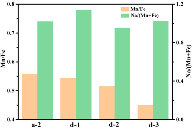
(Mn/Fe) and Na/(Mn + Fe) content of the products prepared with the defensive side containing different chelating agents.
Figure 8.

Charge–discharge curves of the samples prepared with the defective side containing different chelating agents.
3.3. Design Principles of Binary Hexacyanoferrate
Finally, we tried to summarize the design principles to achieve flexible regulation of the structures as we expected. In our opinion, there were two routes to substitute Mn during the ion-exchange process. As shown in Figure 9, one route was that the ion exchange took place in the bulk structure, substituting Mn to form Nax(MnFe)[Fe(CN)6]y, which was a result of the solid solution reaction during sodiation and desodiation. The solid solution with a homogeneous distribution of Fe and Mn in the core was due to the fast diffusion of Fe2+ in the solid MnHCF to achieve the thermodynamic metastable state. However, on the premise of the formation of solid solution, the ion-exchange rate should be controlled as low as possible, such as lowering the Fe2+ concentration in the attack side through introducing the chelating agent. Otherwise, a high ion-exchange rate tended to form the kinetic product, where Fe was more concentrated on the surface. The process corresponded to the other route that the Fe2+ reacted with Fe(CN)64– dissociated from MnHCF and reprecipitated on the MnHCF particles to form core–shell structures. This route was driven by the difference between the Ksp of FeHCF and MnHCF. Of course, the chelating agent on the defensive side would greatly promote the dissolution of MnHCF and a thicker shell of FeHCF would also be obtained. However, these two routes did not work alone but proceeded simultaneously, and the final product depended on the competition between the dissolution–reprecipitation to form FeHCF and the ion-exchange to form Nax(MnFe)[Fe(CN)6]y. Thus, the final structure could be reasonably described as a core/shell structure, shown in Figure 9, where the core was enriched with solid solution Nax(MnFe)[Fe(CN)6]y and the shell was enriched with FeHCF.
Figure 9.

Schematic diagram of the proposed ion-exchange process toward the binary PBAs synthesis.
In following, we attempted to test our proposed mechanism by case design. For the ion-exchange process based on MnHCF, the relative solubility of PBAs of different transition metals should be first figured out. Herein, a method based on the change of conductivity was used to judge the relative magnitude of Ksp. As shown in Figure S4, taking the second minute after mixing as the starting point, the order of conductivity attenuation was CuHCF < NiHCF < FeHCF < MnHCF, corresponding to the order of growth rate after nucleation. Furthermore, it could be inferred that the nucleation rate during precipitation process, dependent on supersaturation,23 was CuHCF, NiHCF, FeHCF, and MnHCF from high to low. Herein, we chose the Mn/Ni ion exchange to see what happened different from Mn/Fe ion exchange. The attack side and defensive side were the same as d-1 group except for the replacement of Fe2+ with Ni2+. As shown in Figure S5a, compared with d-1 group, the Ni was more concentrated at the edge of particles. This might result from the solubility difference between AHCF (A = Fe or Ni) and MnHCF. A larger solubility difference between NiHCF and MnHCF would greatly promote the dissolution of MnHCF and the newly formed NiHCF would reprecipitate on the surface. Thus, the Mn/Ni ion exchange was more inclined to form a core/shell structure after ion-exchange, which was also confirmed by previous work.16 We could also design another ion-exchange process to prepare the solid solution with homogeneous distribution of Ni. A common strategy was to decrease both the feeding of Ni in the attack side and the extraction of Mn in the defensive side, which can be achieved by using a stronger chelating agent like sodium gluconate in the attack side, slowing its feeding rate to 0.5 mL/min and removing chelating agent from the defensive side. As shown in Figure S5b, Ni was homogeneously distributed along the scanning line, which could be attributed to the lower ion-exchange rate with a stronger chelating agent and the dramatic decrease of dissolution-reprecipitation rate due to absence of chelating agent in the defensive side.
4. Conclusion
In this work, to figure out the rules of composition regulation during the ion-exchange process, we conducted a case study that chose the electrochemically active Fe as a ion-exchange element (attack side) and the Prussian white slurry with high solid content (MnHCF) as a template (defensive side). We systematically studied the effect of two sides on the final structure characterized by the EDS line scan, ICP-MS, and initial charge–discharge curve. It was found that the final product generally tended to form a core/shell structure as a whole, where the shell was NaxFeFe(CN)6 (FeHCF) and the core was solid solution Nax(FeMn)Fe(CN)6. The proportions of two structures were mainly controlled by the competition between the ion-exchange rate in the bulk material and the dissolution-reprecipitation rate. Slowing down the attacking rate, such as use of chelating agent complexed with the attacker Fe, was advantageous to form the thermodynamically metastable state with homogeneous distribution of Fe and Mn due to the fast diffusion of Fe2+ in the MnHCF. The FeHCF could be adjusted by the dissolution-reprecipitation rate, which was driven by the solubility difference. Adding the chelating agent in the defensive side would promote the dissolution of MnHCF and reprecipitation of FeHCF on the surface. Meanwhile, with the increase of Fe sources, the thickness of shell FeHCF increased and correspondingly the content of solid solution decreased because FeHCF was more stable than the solid solution in thermodynamics. Finally, such a design principle in this case study could also be generalized to other ion-exchange processes. The larger difference between template and newly generated MHCF inclined to form core/shell structures due to the enhancement of dissolution–reprecipitation route. In summary, using the simple ion-exchange process capable of processing a high solid content, we could achieve flexible regulation of core–shell structures, which is fundamental to study the structure–performance relationship in the future.
Acknowledgments
This work was supported by the National Natural Science Foundation of China under grants 21422603, U1662120, and 21978152.
Supporting Information Available
The Supporting Information is available free of charge at https://pubs.acs.org/doi/10.1021/acsomega.1c07106.
XRD refinement (Figure S1), Raman spectra (Figure S2), EDS line scans (Figure S3 and S5) of the particles, and comparison of the change in conductance vs time during particle growth of the Ni/Fe/Mn/Cu hexacyanoferrate (Figure S4) (PDF)
The authors declare no competing financial interest.
Supplementary Material
References
- Hurlbutt K.; Wheeler S.; Capone I.; Pasta M. Prussian Blue Analogs as Battery Materials. Joule 2018, 2 (10), 1950–1960. 10.1016/j.joule.2018.07.017. [DOI] [Google Scholar]
- Chapman K. W.; Southon P. D.; Weeks C. L.; Kepert C. J. Reversible hydrogen gas uptake in nanoporous Prussian Blue analogues. Chem. Commun. 2005, (26), 3322–4. 10.1039/b502850g. [DOI] [PubMed] [Google Scholar]
- Simonov A.; De Baerdemaeker T.; Bostrom H. L. B.; Rios Gomez M. L.; Gray H. J.; Chernyshov D.; Bosak A.; Burgi H. B.; Goodwin A. L. Hidden diversity of vacancy networks in Prussian blue analogues. Nature 2020, 578 (7794), 256–260. 10.1038/s41586-020-1980-y. [DOI] [PMC free article] [PubMed] [Google Scholar]
- Chen G.-R.; Chang Y.-R.; Liu X.; Kawamoto T.; Tanaka H.; Kitajima A.; Parajuli D.; Takasaki M.; Yoshino K.; Chen M.-L.; Lo Y.-K.; Lei Z.; Lee D.-J. Prussian blue (PB) granules for cesium (Cs) removal from drinking water. Sep. Purif. Technol. 2015, 143, 146–151. 10.1016/j.seppur.2015.01.040. [DOI] [Google Scholar]
- Li Y.; Li C. H.; Talham D. R. One-step synthesis of gradient gadolinium ironhexacyanoferrate nanoparticles: a new particle design easily combining MRI contrast and photothermal therapy. Nanoscale 2015, 7 (12), 5209–5216. 10.1039/C4NR06481J. [DOI] [PubMed] [Google Scholar]
- Presle M.; Maurin I.; Maroun F.; Cortès R.; Lu L.; Sayed Hassan R.; Larquet E.; Guigner J.-M.; Rivière E.; Wright J. P.; Boilot J.-P.; Gacoin T. Photostrictive/Piezomagnetic Core–Shell Particles Based on Prussian Blue Analogues: Evidence for Confinement Effects?. J. Phys. Chem. C 2014, 118 (24), 13186–13195. 10.1021/jp501758b. [DOI] [Google Scholar]
- Hou P.; Zhang H.; Zi Z.; Zhang L.; Xu X. Core–shell and concentration-gradient cathodes prepared via co-precipitation reaction for advanced lithium-ion batteries. J. Mater. Chem. A 2017, 5 (9), 4254–4279. 10.1039/C6TA10297B. [DOI] [Google Scholar]
- Hu P.; Peng W.; Wang B.; Xiao D.; Ahuja U.; Réthoré J.; Aifantis K. E. Concentration-Gradient Prussian Blue Cathodes for Na-Ion Batteries. ACS Energy Lett. 2020, 5 (1), 100–108. 10.1021/acsenergylett.9b02410. [DOI] [Google Scholar]
- Jeon S.; Li C. H.; Talham D. R. Design and Synthesis of Concentration Gradient Prussian Blue Analogues. Cryst. Growth Des. 2021, 21 (2), 916–925. 10.1021/acs.cgd.0c01271. [DOI] [Google Scholar]
- Wang B.; Han Y.; Chen Y.; Xu Y.; Pan H.; Sun W.; Liu S.; Yan M.; Jiang Y. Gradient substitution: an intrinsic strategy towards high performance sodium storage in Prussian blue-based cathodes. J. Mater. Chem. A 2018, 6 (19), 8947–8954. 10.1039/C8TA02291G. [DOI] [Google Scholar]
- Ma Y.; Ma Y.; Dreyer S. L.; Wang Q.; Wang K.; Goonetilleke D.; Omar A.; Mikhailova D.; Hahn H.; Breitung B.; Brezesinski T. High-Entropy Metal-Organic Frameworks for Highly Reversible Sodium Storage. Adv. Mater. 2021, 33 (34), 2101342. 10.1002/adma.202101342. [DOI] [PMC free article] [PubMed] [Google Scholar]
- Gebert F.; Cortie D. L.; Bouwer J. C.; Wang W.; Yan Z.; Dou S. X.; Chou S. L. Epitaxial Nickel Ferrocyanide Stabilizes Jahn-Teller Distortions of Manganese Ferrocyanide for Sodium-Ion Batteries. Angew. Chem., Int. Ed. Engl. 2021, 60 (34), 18519–18526. 10.1002/anie.202106240. [DOI] [PubMed] [Google Scholar]
- Xie B.; Zuo P.; Wang L.; Wang J.; Huo H.; He M.; Shu J.; Li H.; Lou S.; Yin G. Achieving long-life Prussian blue analogue cathode for Na-ion batteries via triple-cation lattice substitution and coordinated water capture. Nano Energy 2019, 61, 201–210. 10.1016/j.nanoen.2019.04.059. [DOI] [Google Scholar]
- Sun J.; Ye H.; Oh J. A. S.; Sun Y.; Plewa A.; Wang Y.; Wu T.; Zeng K.; Lu L. Alleviating mechanical degradation of hexacyanoferrate via strain locking during Na+ insertion/extraction for full sodium ion battery. Nano Res. 2022, 15, 2123. 10.1007/s12274-021-3844-7. [DOI] [Google Scholar]
- Zhao Q.; Wang W.; Li Y.-t.; Wu N.; Guo Y.-d.; Cheng W.-j.; Sun W.-w.; Li J.-z.; Zhou A.-j. Ion-exchange surface modification enhances cycling stability and kinetics of sodium manganese hexacyanoferrate cathode in sodium-ion batteries. Electrochim. Acta 2021, 390, 138842. 10.1016/j.electacta.2021.138842. [DOI] [Google Scholar]
- Feng F.; Chen S.; Zhao S.; Zhang W.; Miao Y.; Che H.; Liao X.-Z.; Ma Z.-F. Enhanced electrochemical performance of MnFe@NiFe Prussian blue analogue benefited from the inhibition of Mn ions dissolution for sodium-ion batteries. Chem. Eng. J. 2021, 411, 128518. 10.1016/j.cej.2021.128518. [DOI] [Google Scholar]
- Shang Y.; Li X.; Song J.; Huang S.; Yang Z.; Xu Z. J.; Yang H. Y. Unconventional Mn Vacancies in Mn–Fe Prussian Blue Analogs: Suppressing Jahn-Teller Distortion for Ultrastable Sodium Storage. Chem. 2020, 6 (7), 1804–1818. 10.1016/j.chempr.2020.05.004. [DOI] [Google Scholar]
- Gao H.; Xin S.; Xue L.; Goodenough J. B. Stabilizing a High-Energy-Density Rechargeable Sodium Battery with a Solid Electrolyte. Chem. 2018, 4 (4), 833–844. 10.1016/j.chempr.2018.01.007. [DOI] [Google Scholar]
- Xi Y.; Lu Y. Rapid synthesis of sodium-rich Prussian white for Sodium-ion battery via a bottom-up approach. Chem. Eng. J. 2021, 405, 126688. 10.1016/j.cej.2020.126688. [DOI] [Google Scholar]
- Li W.; Han C.; Wang W.; Xia Q.; Chou S.; Gu Q.; Johannessen B.; Liu H.; Dou S. Stress Distortion Restraint to Boost the Sodium Ion Storage Performance of a Novel Binary Hexacyanoferrate. Adv. Energy Mater. 2020, 10 (4), 1903006. 10.1002/aenm.201903006. [DOI] [Google Scholar]
- Xi Y.; Lu Y. Facile synthesis and cycling performance maintenance of iron hexacyanoferrate cathode for sodium-ion battery. J. Power Sources 2021, 513, 230554. 10.1016/j.jpowsour.2021.230554. [DOI] [Google Scholar]
- Song J.; Wang L.; Lu Y.; Liu J.; Guo B.; Xiao P.; Lee J. J.; Yang X. Q.; Henkelman G.; Goodenough J. B. Removal of interstitial H2O in hexacyanometallates for a superior cathode of a sodium-ion battery. J. Am. Chem. Soc. 2015, 137 (7), 2658–2664. 10.1021/ja512383b. [DOI] [PubMed] [Google Scholar]
- Devos C.; Van Gerven T.; Kuhn S. Nucleation kinetics for primary, secondary and ultrasound-induced paracetamol crystallization. CrystEngComm 2021, 23 (30), 5164–5175. 10.1039/D1CE00676B. [DOI] [Google Scholar]
Associated Data
This section collects any data citations, data availability statements, or supplementary materials included in this article.