Abstract
Introducing CO2 electrochemical conversion technology to the iron-making blast furnace not only reduces CO2 emissions, but also produces H2 as a byproduct that can be used as an auxiliary reductant to further decrease carbon consumption and emissions. With adequate H2 supply to the blast furnace, the injection of H2 is limited because of the disadvantageous thermodynamic characteristics of the H2 reduction reaction in the blast furnace. This paper presents thermodynamic analysis of H2 behaviour at different stages with the thermal requirement consideration of an iron-making blast furnace. The effect of injecting CO2 lean top gas and CO2 conversion products H2–CO gas through the raceway and/or shaft tuyeres are investigated under different operating conditions. H2 utilisation efficiency and corresponding injection volume are studied by considering different reduction stages. The relationship between H2 injection and coke rate is established. Injecting 7.9–10.9 m3/tHM of H2 saved 1 kg/tHM coke rate, depending on injection position. Compared with the traditional blast furnace, injecting 80 m3/tHM of H2 with a medium oxygen enrichment rate (9%) and integrating CO2 capture and conversion reduces CO2 emissions from 534 to 278 m3/tHM. However, increasing the hydrogen injection amount causes this iron-making process to consume more energy than a traditional blast furnace does.
Keywords: blast furnace, hydrogen injection, gas utilisation efficiency, energy consumption, CO2 emission
1. Introduction
Traditional blast furnace (BF) iron making relies on carbon and contributes to over 70% of CO2 emissions in the iron and steel industry [1]. In a blast furnace, coke is converted into a high-temperature CO gas and performs an exothermic reaction with iron ores, resulting in a large amount of CO and CO2 leaving the furnace with top gas. Typically, every tonne of hot metal (tHM) produced from a traditional BF requires about 500 kg/tHM carbon and generates around 1.2 tonnes of CO2 emissions [2,3]. Hence, there were various attempts for a clean iron-making process to reduce CO2 emissions [4,5,6,7]. One of the approaches is using alternative reductants produced from renewable energies to replace carbon. BF operation with hydrogen as an auxiliary reducing agent was extensively investigated because of its specific advantages over CO [8,9,10,11,12]. Compared to CO reduction that generates CO2, reducing iron ores by hydrogen only forms water vapor. Kinetically, hydrogen enables a higher gas flow rate, and a faster reduction in iron ores and productivity than only CO does [13,14]. The higher thermal conductivity of hydrogen helps in heat transfer efficiency between solid and gas phases [15]. In addition, the hydrogen reduction in iron ores suppresses the strong endothermic direct reduction in iron ores. However, hydrogen reduction is thermally more disadvantageous than CO reduction. Due to this endothermic reduction in iron ores by hydrogen, hydrogen addition changes the energy supply of the BF, and it is only useful to a certain extent [16,17,18].
Few previous experiments and mathematical models have investigated the maximal or optimal hydrogen injection to the BF, and results are controversial and need further investigation. A thermogravimetric experiment showed the efficiency of hydrogen on reduction rate is neglected when its content is lower than 5%, and H2 content should be 5% to 15% at reduction temperatures between 700 and 1000 °C [13,19]. Wang et al. performed a pulverisation experiment at 900 °C with 70% N2 and found that the reduction degree of burdens was more than 90% when H2 content was higher than 20% [20]. On the basis of reduction experiments, Lyu et al. reported that the appropriate H2 content lies between 5% to 10% in terms of the reduction rate, gas utilisation, and reasonable distribution of the energy in the BF in the CO and H2 mixture [17]. Nogami et al. used a multiphase fluid dynamic model to simulate the effect of hydrogen injection with 2.5% oxygen enrichment [8]. They demonstrated that the coke rate decreases linearly, and the maximal hydrogen injection can reach 43.7%.
The application of hydrogen in large-scale BF iron-making processes is limited due to its supply in terms of cost, availability, storage, and transportation [21,22]. The traditional BF contains a low level of hydrogen content because it only generates from the blast air moisture and the volatiles of pulverised coal. One opportunity for BF hydrogen enrichment is injecting hydrogen-rich (so-called H2-rich) gas or hydrogen-bearing materials from external sources, including natural gas, fuel oil, coke oven gas (COG), reformed gas, and waste plastics (CnHm) [23,24,25,26]. Previous studies adopted photocatalysis to produce CO and H2 from CO2. However, the productivity of photocatalysis is less than 1000 µmol CO/gCO2 and 19 µmol H2/gCO2 [27,28]. It is challenging for photocatalysis to meet the large-scale CO2 conversion requirement in the iron-making process. Electrochemical CO2 conversion is one option that can recycle carbon into blast furnace gas (BFG) as CO [29]. The high energy demand is considered to be a major difficulty for electrochemical reduction in CO2 [30]. However, it provides an added opportunity for a BF because hydrogen is coproduced in the electrolyser, which can be used for iron-ore reduction. In low-temperature electrolysis cells, CO2 reduction is carried out in aqueous solutions, and different levels of current density can be used to produce hydrogen at various concentrations [31,32,33]. As an additional benefit, a pure oxygen stream is generated as another byproduct during electrolysis, which can be used directly for oxygen enrichment to the BF [34]. In this study, we use CO2 capture and utilisation (CCU) technology to provide a reliable on-site H2-rich gas for the BF iron-making process while avoiding CO2 emissions. Renewable energy can be coupled to CO2 electrolysis to achieve further emission reduction.
This study aims to use a modelling method to predict hydrogen involvement in the BF and determine the CO2 emission reduction potential. An alternative method to determine the hydrogen utilisation efficiency is developed. First, thermodynamic and thermal balance models are introduced; then, hydrogen injection is quantitatively studied to determine the optimal injection position and volume by considering key BF performance indices. Lastly, the effect of hydrogen injection on coke consumption, gas utilisation efficiency, and the energy consumption of the iron-making system are investigated.
2. Materials and Methods
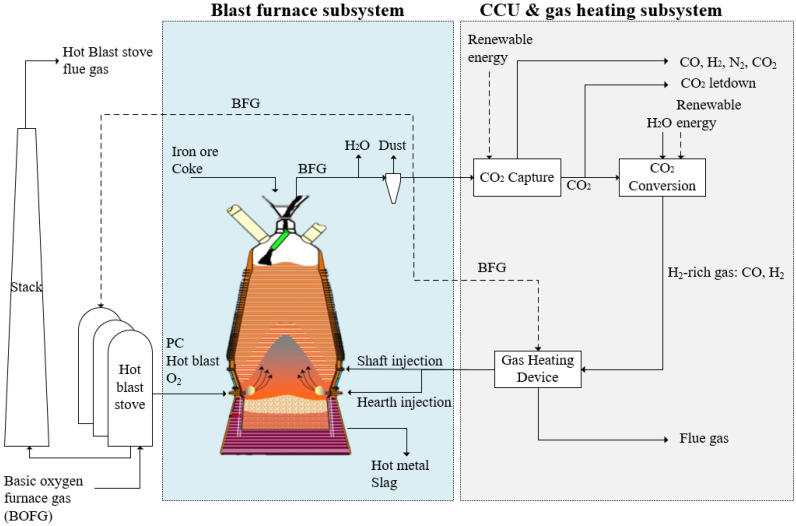
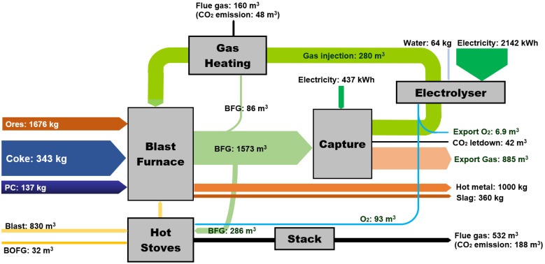
Here, we studied the effect of H2-rich gas injection through BF tuyeres at the raceway position and/or shaft tuyeres, as shown in Figure 1. The BF is studied as the main subsystem when changing the hydrogen injection condition. The CCU and gas heating subsystem is used as a black box to provide necessary input information to BF. The BFG composition and flow rate from BF are the input for the CCU unit, and the CCU unit provides H2-rich reducing gas as the input to the BF. The operating conditions for this BF to produce 1 tonne hot metal (1 tHM) are listed in Table 1 and were kept constant throughout simulations. The overall CO content in the gas injectant was maintained at 200 m3/tHM. The productivity of this BF is 238 tHM per hour.
Figure 1.
Blast furnace process with CO2 capture, conversion, and H2-rich gas injection.
Table 1.
Operating conditions of the simulation.
| Operating Parameters | |
|---|---|
| PCI rate (kg/tHM) | 137 |
| Blast temperature, °C | 1052 |
| Humidity of hot blast, g/m3 | 12.93 |
| Top gas temperature, °C | 161 |
| Hearth injection temperature, °C | 1250 |
| Shaft injection temperature, °C | 900 |
As shown in Figure 1, hot oxygen-enriched blast and pulverised coal is injected through the tuyeres. The upper limit of oxygen enrichment rate for the blast was set at 14% to maintain the stable operation of the large-scale BFs. After drying and dust removal, some BFG is combusted in the hot blast stoves to heat cold blast, and in the gas heating device to provide high-temperature gas injectants. The rest of BFG enters the amine absorption CO2 capture unit to provide a CO2-rich stream that is processed in an electrochemical CO2 conversion unit to produce a CO and H2 stream containing, for example, 30% vol. H2 and 70% vol. CO. The CO2-lean stream from the top of the CO2 capture unit contained a mix of CO, H2, and N2 that is exported to other processes in the integrated steel mill. We did not in this study consider additional separation of CO and H2 from the N2 in this stream for recycling back to the BF. Oxygen enrichment is required with H2-rich gas injection to provide heat to the BF and enrich BFG for CO2 capture [35]. The BF can take another advantage from the CCU unit, as the electrolyser produces pure oxygen in another effluent stream. Besides BFG, a small amount of the basic oxygen furnace gas (i.e., BOFG) from steel making is usually combusted as fuel to a hot blast stove. Following assumptions of the BF, CCU unit, gas heating device and hot stove are made in this study:
Degree of indirect reduction depends on the reducing gas concentration of BF bosh gas, which is estimated by an empirical equation, as shown in Equation (1) [36]:
| (1) |
where is the proportion of H2 and CO in the total amount of gas entering the bosh and shaft.
For the amine absorption CO2 capture unit: 30% monoethanolamine (MEA) concentration was used for CO2 capture in this study. The capture unit recovered 90% CO2 in BFG, and the CO2 purity was >99%; the general thermal energy requirement for capture was assumed to be around 1000 kWh/tCO2 (3.6 GJ/ tCO2) [37,38,39]. Any additional CO2 captured and not converted was assumed to be released as per current operation or could be sent to CO2 storage routes, shown as CO2 letdown in Figure 1.
The electrochemical CO2 conversion unit was treated in the model as a simplified input–output model. Assumptions for the material and energy balance in the CO2 conversion unit were based on laboratory demonstration data with additional inputs from literature sources. Briefly, the model was based on multiple two-cell vapour fed electrolyser stacks with the capacity to treat 50 tCO2 per day; further details can be found in our other report [33]. The current density of the electrolyser was altered from 2.68 V at 0 A/m2 to 3.59 V at 1862 A/m2 to produce the H2-rich gas with different H2/CO compositions.
The electricity consumption for CO2 conversion is proportional to the H2 generation, which can be estimated as in Equation (2) [33]:
| (2) |
where is the power required for the CO2 conversion unit, kWh/tHM; is the amount of H2 generated by the conversion unit, m3/tHM;
efficiency of the gas heating device was 85%;
The hot blast stove system uses two stoves on-gas and one stove on-blast, and the efficiency of the hot blast stoves was 75%.
As indicated in Figure 1, CO2 capture and conversion units use renewable energy to avoid their own CO2 emissions. The type of renewable power used by the industry depends on availability and cost, such as solar power [40,41]. Besides solar power, industries can use thermal–electrical materials to recover a large amount of waste heat in an integrated steel mill to provide electricity for CCU units [42]. In addition, using the lower heating value energy to generate electricity in the steel mill and the on-site power plant can help to minimise the renewable power periodic availability problem.
To achieve the objectives of this study, two mathematical models were developed. As a reducing agent, H2-rich gas needs to fulfil the thermodynamic requirement of the reduction reaction to capture oxygen in iron ores. H2-rich gas also needs to provide enough heat in the shaft for keeping an effective reduction process. First, hydrogen behaviour in different parts of the BF was analysed. A thermodynamic model for hydrogen reduction was built to determine hydrogen utilisation efficiency. This model provides a guideline of the proper hydrogen injection concentration. Then, a thermal balance model was used to limit the hydrogen injection temperature and volume.
The optimal hydrogen injection amount and position were determined by increasing the reduction potential in the coke consumption and CO2 emissions, increasing gas utilisation efficiency and lowering the energy consumption. A static mass balance model of the BF was used to calculate the above parameters.
2.1. Thermodynamic Calculations of H2-Rich Gas Injection BF
The reduction behaviours of injected gas are discussed in different parts of the BF to determine the reducing gas utilisation.
2.1.1. Raceway
In the BF raceway, the main reactions considered in this study were carbon combustion, coke solution loss reaction between coke and CO2, water–gas reaction between coke and moisture in the hot blast, which can be described as shown in Equations (3)–(5):
| (3) |
| (4) |
| (5) |
With excess coke existing in the BF bottom, it could be assumed that CO and H2 combustion was negligible. This could be justified by the assumption that, if a small amount of H2 reacts with O2 to form water in the raceway, the generated water vapour reacts with coke and turn back to H2. Therefore, this process can be simplified as heating the hearth gas injectant, as shown in Equation (6):
| (6) |
where is hearth gas injection temperature, °C; denotes specific heat capacity of the gas injected to BF, kJ/m3°C; is hearth injection volume, m3/tHM; and is the sensible heat carried by the gas injected to BF, kJ/tHM.
2.1.2. Dripping, Cohesive, and High-Temperature Zones over 1000 °C
The primary reaction in the dripping zone is a direct reaction between coke and FeO. Hot gas containing H2 and CO that passes through the cohesive zone reacts with molten FeO or semi-molten FeO to form H2O and CO2. As the temperature was over 1350 °C in the dripping zone, the amount of CO2 was negligible due to the solution loss reaction. At the high-temperature zone over 1000 °C, some reduced FeO and Fe3O4 were still in the solid state, and H2 could pass through their surface. Almost all the H2O produced by H2 reduction rapidly participates in water–gas reaction at the presence of coke to form CO and H2 over 1273 K (1000 °C). Therefore, the reduction reaction in this section was essentially the direct reduction in iron by coke. H2 injected through the tuyeres at the raceway mainly catalyses direct reduction and heats the molten or semi-molten burden.
2.1.3. Shaft Zone Temperature between 800 and 1000 °C
According to the thermodynamics of iron oxide reduction and dynamics studies, H2 has better reducing capability than that of CO above 800 °C [43,44]. At the same time, the extent of coke solution loss reaction and the water–gas reaction was less than that in the higher temperature zone. In this temperature zone, H2 reacts with various iron oxides to generate H2O, and the formed H2O is not gasified into H2 by carbon completely. Therefore, it is the primary zone to improve H2 utilisation efficiency.
The H2-rich reducing gas utilisation rate and volume requirement vary in different ferric oxides reduction stages. The iron oxides reduction reactions are at a nonequilibrium state in the BF. When the temperature is above 570 °C, the reduction in ferric oxides by CO and H2 in the BF occurs in the following sequences: 1/2 Fe2O3 1/3 Fe3O4 (Stage I) → FeO (Stage II) → Fe (Stage III) [45]. The gas produced by the reduction in the latter stage is the reducing gas for the previous stage. Heat is gradually transferred to solid materials during the gas ascending. At the same time, part of reducing gas reacts with iron oxides and converts into CO2 and H2O, and finally forms top gas at around 150 to 250 °C when leaving the BF. There are 25% of the total oxygen elements removed during the reduction of Fe3O4 into FeO, and the remaining 75% of oxygen elements were removed in reducing FeO to Fe. Therefore, the reduction process from FeO to Fe is the key step. The required reducing gas amount is kmol for CO, and kmol for H2 to produce 1 kmol iron. The value of and is the excess coefficient. The reduction reactions and thermodynamic parameters in Stage III for CO and H2 are expressed as in Equations (7)–(12), and Equations (13)–(17), respectively [46]:
| (7) |
| (8) |
| (9) |
| (10) |
where K is the reaction equilibrium constant; φ denotes the fraction of gas component.
The minimal CO required for Stage III is described in Equation (11):
| (11) |
The utilisation efficiency of CO in Stage III, , is described in Equation (12):
| (12) |
| (13) |
| (14) |
| (15) |
The minimal H2 required for Stage III is calculated as in Equation (16):
| (16) |
The utilisation efficiency of H2 in Stage III, is described in Equation (17):
| (17) |
According to the theoretical thermochemical calculations, 50% of H2 and CO participates in the water–gas shift reaction Equation (18) between 600 and 1400 °C [47]. Therefore, the heat consumed by the water–gas shift reaction at temperatures above 820 °C is balanced by the heat generated at the temperature below 820 °C, as calculated by Equation (19). However, H2 promotes iron ore reduction by CO via the water gas shift reaction when the temperature is over 820 °C [48]. The CO2 generated reacts with H2 to reform CO, which participates in FeO reduction reaction again and improve the utilisation efficiency of CO.
| (18) |
| (19) |
The heat effect of FeO reduction by H2 and CO gas is calculated by Equation (20):
| (20) |
where is the proportion of CO or H2 in the reducing gas entering the BF shaft.
The gas produced by the reduction in Stage III is the reducing gas for Stage II. The reduction reactions and thermodynamic parameters in Stage II for CO and H2 are expressed in Equations (21)–(28):
| (21) |
| (22) |
| (23) |
| (24) |
| (25) |
| (26) |
| (27) |
| (28) |
The minimal CO and H2 volume required for Stage II is calculated as shown in Equations (29) and (30), respectively:
| (29) |
| (30) |
The utilisation efficiency of CO and H2 in Stage II is calculated as shown in Equations (31) and (32), respectively:
| (31) |
| (32) |
In the first stage of iron ores reduction, the transformation of Fe2O3 to Fe3O4 is very rapid due to the very high equilibrium constant of Fe2O3 reduction above 600 K, as shown in Equations (33) and (35):
| (33) |
| (34) |
| (35) |
| (36) |
The gas produced by the reduction in Stage II provides the reducing gas for Stage I. These reactions only require a low concentration of reducing gas to proceed. The minimal CO and H2 volume required for Stage I is shown in Equations (37) and (38), respectively. With utilisation efficiency close to 100%, Fe2O3 reduction is an irreversible reaction.
| (37) |
| (38) |
The utilisation efficiency of CO and H2 in Stage I is described by Equations (39) and (40), respectively:
| (39) |
| (40) |
The overall gas utilisation efficiency for H2-rich reducing gas in the BF is calculated as in Equation (41) below:
| (41) |
Assuming the water generated in the Fe2O3 reduction is reacted with CO, in which H2 performs only as a catalyst of CO reduction of Fe2O3. The water in top gas is determined by H2 utilisation efficiency in FeO and Fe3O4, which was calculated as in Equation (42):
| (42) |
Since FeO reduction is the key step, the theoretical overall H2 utilisation efficiency was calculated as shown in Equation (43). The highest theoretical H2 utilisation efficiency can be obtained with the minimal H2 requirement value on the basis of the thermodynamic requirement in Stage III, and this highest value is determined by temperature. Due to thermal restrictions and excess H2 injected, the actual gas utilisation efficiency can only approach this theoretical value. The actual thermodynamic utilisation efficiency of H2 is a function of the amount of H2 introduced to the BF, as shown in Equation (43):
| (43) |
As the FeO reduction is the key step in the indirect reduction process, the thermodynamic requirement of gas entering the BF shaft to produce 1 tHM is calculated as in Equations (44) and (45):
| (44) |
| (45) |
where is the amount of gas raised from BF bosh after direct reduction and the gas injected through the shaft tuyeres, m3/tHM; is the proportion of iron content in hot metal; is the degree of direct reduction.
2.2. Thermal Calculations of H2-Rich Gas Injection BF
As the heat carrier, the H2-rich gas injected through raceway tuyeres needs to compensate for the required energy in the lower furnace and maintain the theoretical combustion temperature at a reasonable range. The gas injected through the shaft also needs to satisfy the heat requirement in the upper furnace. The energy of H2-rich gas includes the oxidation heat release from the iron ore reduction and sensible heat. The oxidation heat release depends on gas utilisation efficiency and gas composition. The injection temperature determines the sensible heat. Thermal calculations for determining the amount of H2-rich gas were developed by a static mass and energy model of the iron-making process.
The thermal balance for this iron-making process is developed in the lower and upper furnaces, divided by the shaft gas injection position. In this work, the lower furnace included BF raceway, dripping zone, and cohesive zone. The thermal balance of the lower furnace is shown in Equation (46) below:
| (46) |
where the heat income in the lower furnace includes: = combustion heat of coke and pulverised coal in front of tuyeres, kJ/tHM; = sensible heat of the hot blast, kJ/tHM; = sensible heat of H2-rich gas injection to the hearth, kJ/tHM; = heat of the coke brings to the lower part of BF, kJ/tHM; = sensible heat of the iron ores into the lower part of the BF, kJ/tHM; and the heat expenditure includes: = heat consumption of solution loss reaction due to the possible CO2 in the hearth injection gas, kJ/tHM; = heat consumption of water decomposition in front of tuyeres, kJ/tHM; = heat consumption of pulverised coal decomposition in front of tuyeres, kJ/tHM; = heat brought to the shaft by bosh gas, kJ/tHM; = heat consumption by direct reduction of alloy element, kJ/tHM; = heat consumption by direct reduction of FeO, kJ/tHM; = heat consumption by desulphurisation, kJ/tHM; = sensible heat of hot metal, kJ/tHM; = sensible heat of slag, kJ/tHM; and = heat loss in the lower furnace, kJ/tHM.
With H2-rich gas injection to BF hearth, the raceway adiabatic flame temperature (RAFT) is calculated as in Equation (47):
| (47) |
where is the heat brought to the raceway by coke, kJ/tHM; is the gas volumes of H2, CO and N2 in the raceway, m3/tHM, respectively.
The energy input and output of the BF shaft can be expressed as in Equations (48) and (49), respectively:
| (48) |
| (49) |
where is the heat carried by H2-rich gas injected into the shaft, kJ/tHM; is the heat generation by iron oxides reduction by H2 and CO, kJ/tHM; is the sensible heat carried by iron ores entering the BF top, kJ/tHM; , kJ/tHM is heat loss in the shaft, kJ/tHM.
The heats provided by the reduction reactions from Fe2O3 to Fe3O4, Fe3O4 to FeO, and FeO to Fe by CO and H2 are calculated as from Equations (50)–(52), respectively:
| (50) |
| (51) |
| (52) |
where and are the degree of indirect reduction by CO and H2, as shown in Equations (53) and (54), respectively:
| (53) |
| (54) |
3. Results and Discussion
3.1. Results of the Thermodynamic Model
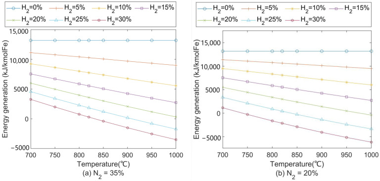
At a medium oxygen enrichment rate (9%), the nitrogen content in the BF shaft is calculated at around 35%. Figure 2a shows the heat effect results based on Equation (20). The FeO reduction reaction transforms from an exothermic into an endothermic process when H2 content increases to 25% around 900 °C. A similar phenomenon shows up when the H2 reaches 20% around 1000 °C. With more H2 participating in the reduction at high temperatures, it causes a severe negative effect on the thermal energy supply to the BF. Therefore, the shaft gas injection temperature should not be too high to reduce its endothermic heat effect and require less preheating in the gas preheating device. The higher oxygen enrichment (less N2 content) enables higher H2 content in the BF, as shown in Figure 2b. It is suggested that with 20% N2 entering the BF shaft, the H2 content should be lower than 25% to avoid too much heat consumption by its reduction reaction.
Figure 2.
Heat effect of FeO reduction in H2–CO–N2 gas mixture at (a) 35% N2 and (b) 20% N2. H2 content entering blast furnace shaft is indicated by different colours.
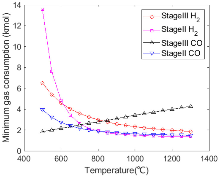
According to Equations (11), (16), (29) and (30), the theoretical minimal H2 and CO requirement with temperature are shown in Figure 3. From this figure, Stage III for iron ores reduction requires more H2 when the temperature is over 625 °C. Stage III requires more CO over 650 °C. In this study, since the gas injection temperature is kept above 820 °C to ensure the high reducing capability of H2, the thermodynamic key step for iron ores reduction is Stage III, and the other stages are proceeded with excess reducing gas. Compared with Fe3O4, FeO reduction requires more reducing gas to proceed, which determines the minimal amount of gaseous mixture. Fe3O4 and Fe2O3 reductions are carried out with excess reducing gas. In addition, the amount of H2 required for FeO reduction at high temperatures is less than the amount of CO required in the reaction. Thermodynamically, injecting H2 content to replace some amount of CO would reduce the total amount of gas mixture and reduce the fuel requirement for the gas preheating. However, CO content in the BF should be enough to meet its thermal condition.
Figure 3.
Variation in minimal gas consumption for iron ores reduction in pure H2 or CO with temperature.
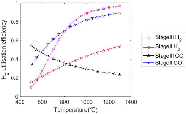
According to Figure 4, gas utilisation efficiency for H2 and CO was similar in Stage II when the temperature was above 820 °C, but H2 utilisation efficiency was much higher than that for CO in Stage III. Although the utilisation efficiency of CO decreases as temperature increases, the FeO reduction reaction would still be promoted with increasing H2 content due to the effect of the water–gas shift reaction.
Figure 4.
Variation in gas utilisation efficiency for iron ores reduction in pure H2 or CO with temperature.
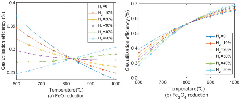
On the basis of the calculation from Equation (41), gas utilisation efficiency at different H2 contents in the reducing gas for FeO and Fe3O4 reduction is shown in Figure 5.
Figure 5.
Gas utilisation efficiency at different H2/CO ratio with temperature in (a) FeO and (b) Fe3O4 reductions.
Figure 5a presents the gas utilisation efficiency of FeO reduction. Due to the endothermic reaction of the H2 reduction, utilisation efficiency of H2-rich reducing gas at 1000 °C for the FeO reduction increased from 23% with no H2 to around 30% with 50% H2 by the equal interval. When H2 content was less than 30% in reducing gas, gas utilisation efficiency in FeO reduction decreased with the increase in temperature. In contrast, gas utilisation efficiency rose with temperature when H2 content is more than 40% in reducing gas. Hence, H2 content in the reducing gas should not be too low to hinder improvement in the gas utilisation efficiency. As shown in Figure 5b, since Fe3O4 reductions by CO and H2 are endothermic, gas utilisation efficiency increases with temperature. The effect of increases in H2 content for Fe3O4 reduction is less than FeO reduction in terms of gas utilisation efficiency. At 1000 °C, gas utilisation efficiency increases by less than 4% when H2 content increases from 0% to 50%. The shaft gas injection temperature should be higher than 820 °C to promote gas utilisation in FeO and Fe3O4 reduction, especially focusing on FeO reduction.
3.2. BF Simulation Conditions and Validation
Without gas injection, the model developed in this work can be used for a traditional BF. The measured data collected from a 2500 m3 BF were used to validate this proposed model. The comparison of the industrial data and the model predictions is summarised in Table 2. The coke rate and top gas components were compared because they are essential measurable parameters that indicate the overall performance of an iron-making BF. The chemical composition of raw material data is shown in Table 3, Table 4 and Table 5. In general, results in this simulation show a similar trend as in practice, and the model was capable of estimating the overall iron-making process. The slight difference in top gas composition is because industrial data contain a slight amount of O2 and CH4 in top gas, which does not exist in this model.
Table 2.
Quantitative validation of the model.
| Parameter | Prediction | Industrial | Top Gas | Prediction | Industrial |
|---|---|---|---|---|---|
| Coke rate, kg/tHM | 386 | 386 | CO, % | 25.1 | 24.9 |
| Blast, Nm3/tHM | 1060 | 1089 | CO2, % | 21.1 | 20.0 |
| Slag rate, kg/tHM | 364 | 373 | H2, % | 1.2 | 0.8 |
| Burden input, kg/tHM | 1676 | 1676 | N2, % | 50.0 | 53 |
| RAFT, °C | 2205 | 2195 | Rd | 0.46 | - |
Table 3.
Chemical composition of raw material and dust, w/w%.
| Composition | Tfe | FeO | SiO2 | CaO | MgO | TiO2 | S | Al2O3 |
|---|---|---|---|---|---|---|---|---|
| Sinter 1 | 55.85 | 9.59 | 5.25 | 10.35 | 2.19 | 0.17 | 0.03 | 2.5 |
| Sinter 2 | 55.85 | 9.2 | 5.26 | 10.27 | 2.2 | 0.27 | - | 2.5 |
| Pellet | 61.92 | 1.46 | 5.31 | 1.45 | - | 1.58 | - | 0.98 |
| Ti ore | 40.27 | - | 9.07 | 2.05 | - | 10.78 | - | 1.69 |
| Dust | 39.80 | 2.58 | 4.05 | 2.04 | 0.83 | 0 | - | 1.31 |
Table 4.
Chemical composition of coke and pulverised coal, w/w%.
| Composition | Fixed C | H2O | FeO | CaO | SiO2 | Al2O3 | MgO | N | O | H | S |
|---|---|---|---|---|---|---|---|---|---|---|---|
| Coke | 86.06 | 4.50 | 1.6 | 0.39 | 4.49 | 3.69 | 0.35 | 0.30 | 0.21 | 0.33 | 1.80 |
| PCI | 71.15 | 0 | 0.03 | 1.98 | 8.4 | 7.93 | 0.18 | 0.34 | 3.16 | 2.10 | 0.30 |
Table 5.
Chemical composition of hot metal, w/w%.
| Composition | Fe | C | Si | Mn | P | S | Ti |
|---|---|---|---|---|---|---|---|
| Hot metal | 95.14 | 4.12 | 0.34 | 0.32 | 0.136 | 0.023 | 0.129 |
3.3. Effect of H2 Injection on Coke Consumption Rate
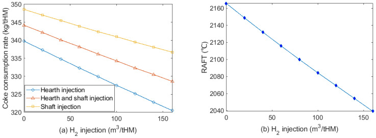
The effect of injecting H2-rich gas to hearth and/or shaft on coke rate is shown in Figure 6. The highest H2 injection rate is limited to 160 m3/tHM to ensure a balanced energy distribution in the BF shaft. Injecting H2 to the BF hearth shows less coke consumption than injecting it to the shaft. This is because it provides more sensible heat to the lower part of the furnace to compensate the heat supplied by coke combustion. The relationship between H2 injection and coke consumption rate at 9% oxygen enrichment rate is given as in Equation (55). Injecting 7.9~10.9 m3/tHM H2 can reduce the coke consumption rate by 1 kg/tHM, depending on the injection position.
| (55) |
where and are the proportion of H2-rich gas injected to the shaft and hearth, respectively; and is the total H2 injection volume to the BF, m3/tHM.
Figure 6.
(a) Coke consumption rate at different H2 injection volumes at different injection positions; (b) effect of H2 injection to hearth on RAFT at 9% oxygen enrichment rate.
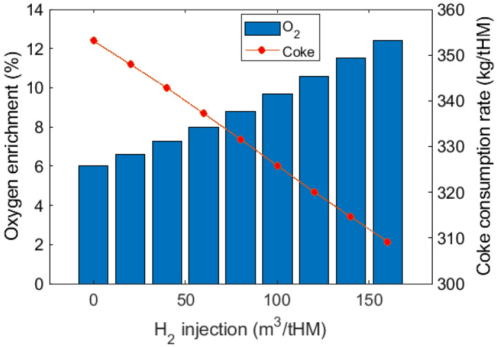
The effect of H2 injection on RAFT at a constant oxygen enrichment rate is shown in Figure 6b. Injecting 20 m3/tHM H2 can reduce RAFT by around 16 °C. Increasing oxygen enrichment can achieve thermal compensation to maintain a stable RAFT and reduce coke consumption, as shown in Figure 7. Compared to the cases without thermal compensation, further reduction in coke consumption is obtained at 309 kg/tHM with 12.4% oxygen enrichment at 160 m3/tHM H2 injection.
Figure 7.
Coke consumption rate at different H2 injection volumes at different oxygen enrichment rates for thermal compensation. RAFT was maintained at 2096 °C in this test.
3.4. Effect on H2 Utilisation Efficiency
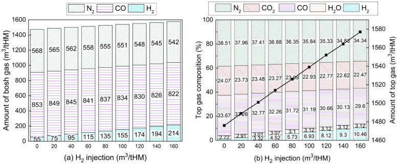
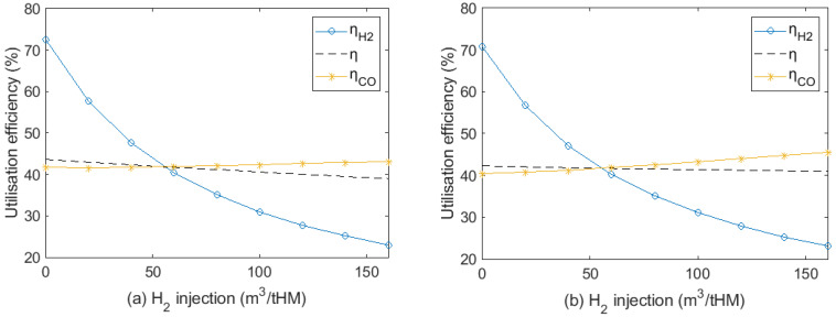
In the case of injecting H2 to hearth, bosh gas composition is shown in Figure 8a. As the H2 injection rate increased from 0 to 160 m3/tHM at a constant CO injection rate, CO content in bosh gas drops due to less coke consumption. N2 content also decreased since less hot blast is required for carbon combustion. There was no H2O in the bosh gas because H2O that formed from the iron oxide reduction by H2 reacted with coke to generate H2 again at high temperature. The amount of top gas and its composition is described in Figure 8b. With more H2 injection, the moisture content in the top gas increases slightly from 2.72% to 3.12% when the H2 injection rate reaches from 0 to 100 m3/tHM. This is because H2 utilisation efficiency significantly dropped from 72.6% to 22.9%, as shown in Figure 9a. CO content in top gas decreased because of less CO in the bosh gas and increased CO utilisation efficiency. CO2 concentration was reduced by less than 2% because there was a significant drop of CO in the bosh gas and increase in CO utilisation efficiency is very limited. The H2 injection promotes CO utilisation with the presence of the water–gas shift reaction. However, the overall effect of the water–gas shift reaction was very limited across the whole BF. The comprehensive gas utilisation efficiency gradually decreased from 43.6% to 39.0% when H2 injection reached 160 m3/tHM.
Figure 8.
Variations of (a) bosh gas and (b) top gas composition with hydrogen injection. (H2 injection at 0 m3/tHM indicates the operating condition of a traditional BF with oxygen enrichment rate at 9%).
Figure 9.
Variations in gas utilisation efficiency with hydrogen injection (a) before and (b) after thermal compensation.
H2 and CO utilisation efficiency after thermal compensation is shown in Figure 9b. Results in this simulation reflect a similar trend as in the literature results [8,49]. Oxygen enrichment increased, and the nitrogen composition in the blast decreased with H2 injection. Hence, there was more increase in reducing gas concentration than that in Figure 9a. With less N2 dilution and stronger indirect reduction, CO utilisation with thermal compensation was enhanced by 5% with H2 injection from 0 to 160 m3/tHM.
By H2 increasing in the BF, CO utilisation increased, and H2 utilisation efficiency decreased. One reason is that water–gas shift reaction Equation (18) would tend to proceed to the right-hand side, and both H2 and CO2 are generated in the upper furnace below 1000 °C. With the regeneration of H2, FeO reduction in Equation (7) can be considered to be proceeding in two successive stages, as shown in Equations (13) and (18):
Due to the smaller size and high diffusivity of H2, the reaction in Equation (13) has an advantage over the reaction in Equation (7). Thus, FeO reduction by CO was promoted by increased H2 content.
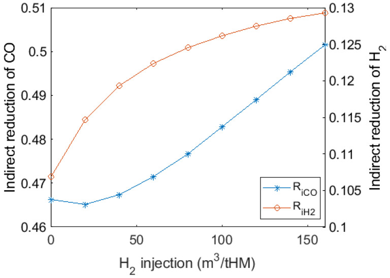
As depicted in Figure 10, with H2 injection and thermal compensation, the degree of indirect reduction increased because H2 reduction replaced part of the direct reduction and oxygen enrichment enhanced reducing gas atmosphere. Since the direct reduction was a huge endothermic reaction process in the lower furnace, less direct reduction reduces coke consumption. Compared to the higher H2 injection volume, injecting 0 to 80 m3/tHM H2 generates more effect on the degree of indirect reduction, from 0.107 to 0.125. Further, the injection of more than 50 m3/tHM H2 significantly increased the indirect reduction of CO. Considering gas utilisation efficiency, H2 injection should be around 50–80 m3/tHM to maintain smooth BF operation and avoid too much excess H2 in top gas.
Figure 10.
Variations in degree of indirect reduction by CO and H2 with H2 injection and thermal compensation.
3.5. Effects on CO2 Emissions and Energy Consumption
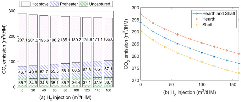
In this work, the CO injected into the BF comes from the CO2 captured in top gas, which reduces CO2 emission compared to a traditional BF process. The emission from CCU can be negligible because it applies renewable electricity. The total emission of this iron-making process includes uncaptured CO2, flue gases from BFG combusted in the preheater and the hot blast stoves, which is shown in Figure 11a. The main CO2 emission reduction comes from the hot stoves. Compared with the traditional BF iron-making system that lacks CCU and gas injection, CO2 emission dropped from 534 to around 272 m3/tHM with 160 m3/tHM H2 injection in this system. When increasing H2 content from 0 to 80 m3/tHM, CO2 emission only decreased by 20 m3/tHM because more BFG was consumed to preheat the injection gas. Additionally, injecting H2-rich gas into the shaft showed more CO2 emission reduction capability than injecting H2 into a hearth or both tuyeres, as shown in Figure 11b.
Figure 11.
CO2 emissions of iron-making process with H2 injection (a) with different CO2 emission sources for shaft injection case; (b) at different injection positions (injection temperature for shaft and hearth was 900 and 1250 °C, respectively).
The energy consumption of the process described in Figure 1 was calculated on the basis of static mass and energy balance, using Equation (56). The standard coal coefficient for each substance in a kilogram of coal equivalent per ton of hot metal (kgce/tHM) is used in this analysis [50].
| (56) |
where is the net energy consumption of the process; is the energy input by coke; is the energy input by pulverised coal; is the energy input by BOFG to the hot blast stoves; is the energy carried by the blast to hot blast stoves; is the electricity required for CO2 capture unit; is the electricity required for CO2 electrolyser, as calculated by Equation (2); is the energy carried by the make-up water required at the humidifier for H2 generation in the electrolsyer; is the energy carried by the BFG that is exported to other processes in the integrated steel mill; and is the energy carried by the oxygen that is generated in the electrolyser and exported to other processes in the integrated steel mill.
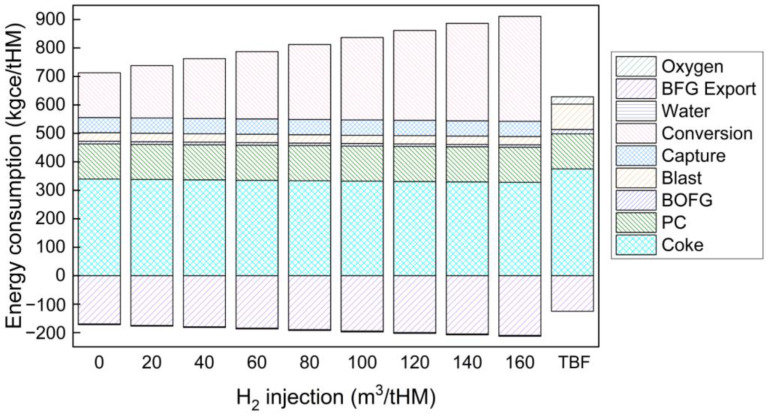
Energy consumption results are shown in Figure 12. In a traditional BF, carbon resources from coke and pulverised coal injection provide the primary energy input, which accounts for 80% in total. When hydrogen is injected into the BF from 0 to 160 m3/tHM, carbon only accounts for 65% to 50% of the total energy consumption. With H2-rich gas injection from 0 to 160 m3/tHM, net energy consumption increased from 541 to 698 kgce/tHM, which is higher than that of the traditional BF (504 kgce/tHM) because electricity required for CO2 conversion to generate H2 kept increasing from 158 to 369 kgce/tHM.
Figure 12.
Energy consumption for H2-rich gas injection BF and traditional BF process (energy carried by the make-up water needed for the CO2 conversion and by BOFG was less than 1% of total energy consumption and thus not indicated in this figure).
In summary, increasing hydrogen injection volume can reduce coke consumption and CO2 emissions. For coke consumption and CO2 emission reduction, the hydrogen injection amount should be as much as possible, as long as it satisfies the energy balance in the BF. In this case, the hydrogen injection amount should be 160 m3/tHM. However, injecting too much H2 significantly reduces its utilisation efficiency and increases the net energy consumption of this process. Further study is recommended to develop a multiobjective optimisation model to balance these effects of hydrogen injection. In general, injecting H2 at around 80 m3/tHM may consume less energy and suppress CO2 emissions under the simulation conditions.
Energy consumption to produce 1 tonne of hot metal in the case of injecting 80 m3/tHM H2 with 200 m3/tHM CO is indicated in Figure 13. Compared to the traditional BF as indicated by Table 2, coke consumption decreased by 43 kg/tHM. CO2 emission dropped from 534 m3/tHM for a traditional BF to 278 m3/tHM in this case (including gas heating flue gas, capture unit CO2 letdown, and stack flue gas). However, electricity consumption in the CO2 capture unit and electrolyser is one of the largest energy inputs. The economic impact of this CCU technology as an auxiliary system to the BF is highly recommended for future investigation.
Figure 13.
Energy and material consumption of the process with 80 m3/tHM hydrogen injection. Relative flow size estimated by energy and demonstrated as bar width.
4. Conclusions
In this study, a thermodynamic model was used to determine the utilisation efficiency of H2-rich gas by considering H2 behaviour at different reduction stages. A static mass and energy balance model of the BF was adopted with this thermodynamic model. The effect of injecting H2-rich gas on BF performance was determined in terms of its coke consumption, CO2 emissions, and energy consumption. Under these simulation conditions, the major findings of this study were:
The desired shaft gas injection temperature should not exceed 1000 °C to suppress the endothermic FeO reduction reaction by H2-rich gas.
Injecting H2 to BF hearth has a better effect on coke rate reduction than that of injection to the shaft. The lowest H2 consumption to save 1 kg of coke was estimated to be 7.9 m3/tHM.
H2 utilisation efficiency dropped significantly with increasing H2 content, and the increase in CO utilisation efficiency was limited. Further research should focus on improving H2 utilisation efficiency with a high H2 injection rate.
Considering H2 utilisation efficiency and the degree of indirect reduction by H2 and CO, the proper H2 injection rate should be from around 50 to 80 m3/tHM.
Introducing H2-rich gas injection can reduce CO2 emissions of the iron-making process by up to 262 m3/tHM compared with a traditional BF. However, injecting too much H2 would hinder CO2 emission reduction due to its requirement of preheating outside the BF.
The energy consumption of this proposed process was higher than that of the traditional BF. Although coke consumption was reduced by 43 kg/tHM more than that of the traditional BF, net energy consumption increased with the amount of injected hydrogen due to the high electricity consumption in the CO2 capture and electrolyser. Developing a CO2 conversion unit with higher efficiency but less energy consumption is strongly recommended.
Acknowledgments
The authors gratefully acknowledge HBIS Group Company Limited for funding support and the scholarship support from the University of Queensland.
Nomenclature
| Abbreviations | |
| BF | Blast furnace |
| PCI | Pulverised coal injection |
| CCU | CO2 capture and conversion unit |
| RAFT | Raceway adiabatic flame temperature |
| tHM | Tonne of hot metal |
| Roman and Greek symbols | |
| Energy, kWh/tHM or kgce/tHM | |
| Volume of gas, m3/tHM | |
| T | Temperature, °C |
| Specific heat capacity, kJ/m3°C | |
| Reaction equilibrium constant of reduction stage i; i = I, II, III | |
| G | Gibbs free energy, kJ/mol |
| Volume fraction of gas component | |
| Utilisation efficiency of CO in stage i, i = 1, 2, 3 | |
| Utilisation efficiency of H2 in stage i, i = 1, 2, 3 | |
| Minimal CO required for iron ores reduction, mol | |
| Minimal H2 required for iron ores reduction, mol | |
| Volume reaction of CO or H2 in reducing gas entering the BF shaft | |
| Overall gas utilisation efficiency for H2-rich reducing gas in the BF | |
| Proportion of H2 and CO in the total amount of gas entering the bosh and shaft. | |
| Sensible heat of material, kJ/tHM | |
| Enthalpy of material, kJ/tHM | |
| Degree of direct reduction | |
| Degree of indirect reduction | |
| Iron content in hot metal | |
| Enthalpy of reaction, kJ/tHM | |
| Weight fraction of solid material | |
| Total H2 injection volume to the BF, m3/tHM | |
Author Contributions
Conceptualization, Y.H., T.E.R., V.R. and G.W.; methodology, Y.H. and G.W.; software, Y.H.; validation, Y.H. and L.H.; formal analysis, Y.H.; investigation, Y.H., Y.Q., J.C. and L.H. resources, L.H.; data curation, Y.H.; writing—original draft preparation, Y.H.; writing—review and editing, Y.H., Y.Q., J.C., L.H., T.E.R. and G.W.; visualization, Y.H.; supervision, T.E.R., V.R. and G.W.; project administration, G.W. and L.H.; funding acquisition, L.H. All authors have read and agreed to the published version of the manuscript.
Funding
This research was funded by HBIS (China) grant number ICSS2017-04.
Institutional Review Board Statement
Not applicable.
Informed Consent Statement
Not applicable.
Data Availability Statement
Data sharing not applicable. No new data were created or analysed in this study. Data sharing is not applicable to this article.
Conflicts of Interest
The authors declare no conflict of interest.
Footnotes
Publisher’s Note: MDPI stays neutral with regard to jurisdictional claims in published maps and institutional affiliations.
References
- 1.Xu K. Low carbon economy and iron and steel industry. Iron Steel. 2010;45:1–12. [Google Scholar]
- 2.Pardo N., Moya J.A. Prospective scenarios on energy efficiency and CO2 emissions in the European Iron & Steel industry. Energy. 2013;54:113–128. doi: 10.1016/j.energy.2013.03.015. [DOI] [Google Scholar]
- 3.Babich A., Senk D. New Trends in Coal Conversion: Combustion, Gasification, Emissions, and Coking. Woodhead Publishing; Sawson, UK: 2019. pp. 367–404. [Google Scholar]
- 4.Danloy G., Berthelemot A., Grant M., Borlée J., Sert D., Van Der Stel J., Jak H., Dimastromatteo V., Hallin M., Eklund N., et al. ULCOS-Pilot testing of the Low-CO2 Blast Furnace process at the experimental BF in Luleå. Rev. Métall.-Int. J. Metall. 2009;106:1–8. doi: 10.1051/metal/2009008. [DOI] [Google Scholar]
- 5.Knop K., Hallin M., Burstrom E. ULCORED SP 12 Concept for minimized CO2 emission. Metall. Res. Technol. 2009;106:419–421. doi: 10.1051/metal/2009073. [DOI] [Google Scholar]
- 6.Material Economics. Industrial Transformation 2050: Pathways to Net-Zero Emisisons from EU Heavy Industry. 2019. [(accessed on 8 January 2022)]. Available online: https://materialeconomics.com/publications/industrial-transformation-2050.
- 7.Chisalita D.-A., Petrescu L., Cobden P., van Dijk H.E., Cormos A.-M., Cormos C.-C. Assessing the environmental impact of an integrated steel mill with post-combustion CO2 capture and storage using the LCA methodology. J. Clean. Prod. 2019;211:1015–1025. doi: 10.1016/j.jclepro.2018.11.256. [DOI] [Google Scholar]
- 8.Nogami H., Kashiwaya Y., Yamada D. Simulation of Blast Furnace Operation with Intensive Hydrogen Injection. ISIJ Int. 2012;52:1523–1527. doi: 10.2355/isijinternational.52.1523. [DOI] [Google Scholar]
- 9.Usui T., Kawabata H., Ono-Nakazato H., Kurosaka A. Fundamental Experiments on the H2 Gas Injection into the Lower Part of a Blast Furnace Shaft. ISIJ Int. 2002;42:S14–S18. doi: 10.2355/isijinternational.42.Suppl_S14. [DOI] [Google Scholar]
- 10.Pinegar H.K., Moats M.S., Sohn H.Y. Process Simulation and Economic Feasibility Analysis for a Hydrogen-Based Novel Suspension Ironmaking Technology. Steel Res. Int. 2011;82:951–963. doi: 10.1002/srin.201000288. [DOI] [Google Scholar]
- 11.Wagner D., Devisme O., Patisson F., Ablitzer D. A laboratory study of the reduction of iron oxides by hydrogen. arXiv. 200808032831 [Google Scholar]
- 12.Spreitzer D., Schenk J. Reduction of Iron Oxides with Hydrogen—A Review. Steel Res. Int. 2019;90:1900108. doi: 10.1002/srin.201900108. [DOI] [Google Scholar]
- 13.Qie Y., Lyu Q., Li J., Lan C., Liu X. Effect of Hydrogen Addition on Reduction Kinetics of Iron Oxides in Gas-injection BF. ISIJ Int. 2017;57:404–412. doi: 10.2355/isijinternational.ISIJINT-2016-356. [DOI] [Google Scholar]
- 14.Zuo H.-b., Wang C., Dong J.-j., Jiao K.-x., Xu R.-s. Reduction kinetics of iron oxide pellets with H2 and CO mixtures. Int. J. Miner. Metall. Mater. 2015;22:688–696. doi: 10.1007/s12613-015-1123-x. [DOI] [Google Scholar]
- 15.Chu M., Nogami H., Yagi J.-I. Numerical Analysis on Injection of Hydrogen Bearing Materials into Blast Furnace. ISIJ Int. 2004;44:801–808. doi: 10.2355/isijinternational.44.801. [DOI] [Google Scholar]
- 16.Yilmaz C., Wendelstorf J., Turek T. Modeling and simulation of hydrogen injection into a blast furnace to reduce carbon dioxide emissions. J. Clean. Prod. 2017;154:488–501. doi: 10.1016/j.jclepro.2017.03.162. [DOI] [Google Scholar]
- 17.Lyu Q., Qie Y., Liu X., Lan C., Li J., Liu S. Effect of hydrogen addition on reduction behavior of iron oxides in gas-injection blast furnace. Thermochim. Acta. 2017;648:79–90. doi: 10.1016/j.tca.2016.12.009. [DOI] [Google Scholar]
- 18.Watakabe S., Miyagawa K., Matsuzaki S., Inada T., Tomita Y., Saito K., Osame M., Sikström P., Ökvist L.S., Wikstrom J.-O. Operation Trial of Hydrogenous Gas Injection of COURSE50 Project at an Experimental Blast Furnace. ISIJ Int. 2013;53:2065–2071. doi: 10.2355/isijinternational.53.2065. [DOI] [Google Scholar]
- 19.Qie Y., Lyu Q., Liu X., Li J., Lan C., Zhang S., Yan C. Effect of Hydrogen Addition on Softening and Melting Reduction Behaviors of Ferrous Burden in Gas-Injection Blast Furnace. Met. Mater. Trans. A. 2018;49:2622–2632. doi: 10.1007/s11663-018-1299-3. [DOI] [Google Scholar]
- 20.Wang Y., He Z.-J., Zhang W.-l., Zhu H.-b., Zhang J.-h., Pang Q.-h. Reduction behavior of iron-bearing burdens in hydrogen-rich stream. Iron Steel. 2020;55:34–40. [Google Scholar]
- 21.Andersson J., Grönkvist S. A comparison of two hydrogen storages in a fossil-free direct reduced iron process. Int. J. Hydrog. Energy. 2021;46:28657–28674. doi: 10.1016/j.ijhydene.2021.06.092. [DOI] [Google Scholar]
- 22.Hydrogen Council Path to Hydrogen Competitiveness: A Cost Perspective. 2020. [(accessed on 8 January 2022)]. Available online: https://hydrogencouncil.com/en/path-to-hydrogen-competitiveness-a-cost-perspective/
- 23.Uribe-Soto W., Portha J.-F., Commenge J.-M., Falk L. A review of thermochemical processes and technologies to use steelworks off-gases. Renew. Sustain. Energy Rev. 2017;74:809–823. doi: 10.1016/j.rser.2017.03.008. [DOI] [Google Scholar]
- 24.Da Rocha E.P., Guilherme V.S., de Castro J.A., Sazaki Y., Yagi J.-I. Analysis of synthetic natural gas injection into charcoal blast furnace. J. Mater. Res. Technol. 2013;2:255–262. doi: 10.1016/j.jmrt.2013.02.015. [DOI] [Google Scholar]
- 25.Halim K.S.A. Theoretical Approach to Change Blast Furnace Regime with Natural Gas Injection. J. Iron Steel Res. Int. 2013;20:40–46. doi: 10.1016/S1006-706X(13)60154-5. [DOI] [Google Scholar]
- 26.Trinkel V., Kieberger N., Bürgler T., Rechberger H., Fellner J. Influence of waste plastic utilisation in blast furnace on heavy metal emissions. J. Clean. Prod. 2015;94:312–320. doi: 10.1016/j.jclepro.2015.02.018. [DOI] [Google Scholar]
- 27.Domingo-Tafalla B., Martínez-Ferrero E., Franco F., Palomares-Gil E. Applications of Carbon Dots for the Photocatalytic and Electrocatalytic Reduction of CO2. Molecules. 2022;27:1081. doi: 10.3390/molecules27031081. [DOI] [PMC free article] [PubMed] [Google Scholar]
- 28.Zhong H., Sa R., Lv H., Yang S., Yuan D., Wang X., Wang R. Covalent organic framework hosting metalloporphyrin-based carbon dots for visible-light-driven selective CO2 reduction. Adv. Funct. Mater. 2020;30:2002654. doi: 10.1002/adfm.202002654. [DOI] [Google Scholar]
- 29.Küngas R. Review—Electrochemical CO2 Reduction for CO Production: Comparison of Low- and High-Temperature Electrolysis Technologies. J. Electrochem. Soc. 2020;167:044508. doi: 10.1149/1945-7111/ab7099. [DOI] [Google Scholar]
- 30.Parvanian A.M., Sadeghi N., Rafiee A., Shearer C.J., Jafarian M. Application of porous materials for CO2 reutilization: A Review. Energies. 2022;15:63. doi: 10.3390/en15010063. [DOI] [Google Scholar]
- 31.Delacourt C., Ridgway P., Kerr J., Newman J. Design of an Electrochemical Cell Making Syngas (CO + H2) from CO2 and H2O reduction at Room Temperature. J. Electrochem. Soc. 2007;155:B42. doi: 10.1149/1.2801871. [DOI] [Google Scholar]
- 32.Lu Q., Jiao F. Electrochemical CO2 reduction: Electrocatalyst, reaction mechanism, and process engineering. Nano Energy. 2016;29:439–456. doi: 10.1016/j.nanoen.2016.04.009. [DOI] [Google Scholar]
- 33.Garg S., Li M., Idros M.N., Wu Y., Wang G., Rufford T.E. Is Maximising Current Density Always the Optimum Strategy in Electrolyser Design for Electrochemical CO2 Conversion to Chemicals? 2021. [(accessed on 8 January 2022)]. Available online: https://chemrxiv.org/engage/chemrxiv/article-details/61a7235f7848050092a110b4.
- 34.De Ras K., Van de Vijver R., Galvita V.V., Marin G.B., Van Geem K.M. Carbon capture and utilization in the steel industry: Challenges and opportunities for chemical engineering. Curr. Opin. Chem. Eng. 2019;26:81–87. doi: 10.1016/j.coche.2019.09.001. [DOI] [Google Scholar]
- 35.De Castro J.A., Takano C., Yagi J.-i. A theoretical study using the multiphase numerical simulation technique for effective use of H2 as blast furnaces fuel. J. Mater. Res. Technol. 2017;6:258–270. doi: 10.1016/j.jmrt.2017.05.007. [DOI] [Google Scholar]
- 36.Zhang W. Doctoral Dissertation. Northeastern University; Shenyang, China: 2015. Fundamental Study and Process Optimization of the Oxygen Blast Furnace Ironmaking. [Google Scholar]
- 37.Kwak N.-S., Lee J.H., Lee I.Y., Jang K.R., Shim J.-G. A study of the CO2 capture pilot plant by amine absorption. Energy. 2012;47:41–46. doi: 10.1016/j.energy.2012.07.016. [DOI] [Google Scholar]
- 38.Bui M., Adjiman C.S., Bardow A., Anthony E.J., Boston A., Brown S., Fennell P.S., Fuss S., Galindo A., Hackett L.A., et al. Carbon capture and storage (CCS): The way forward. Energy Environ. Sci. 2018;11:1062–1176. doi: 10.1039/C7EE02342A. [DOI] [Google Scholar]
- 39.Choi J., Cho H., Yun S., Jang M.-G., Oh S.-Y., Binns M., Kim J.-K. Process design and optimization of MEA-based CO2 capture processes for non-power industries. Energy. 2019;185:971–980. doi: 10.1016/j.energy.2019.07.092. [DOI] [Google Scholar]
- 40.Hari S.R., Balaji C.P., Karunamurthy K. Carbon Capture and Storage Using Renewable Energy Sources: A Review. IOP Conf. Ser. Earth Environ. Sci. 2020;573:12004. doi: 10.1088/1755-1315/573/1/012004. [DOI] [Google Scholar]
- 41.Aresta M., Dibenedetto A., Angelini A. The use of solar energy can enhance the conversion of carbon dioxide into energy-rich products: Stepping towards artificial photosynthesis. Philos. Trans. R. Soc. London. Ser. A Math. Phys. Eng. Sci. 2013;371:20120111. doi: 10.1098/rsta.2012.0111. [DOI] [PubMed] [Google Scholar]
- 42.McBrien M., Serrenho A.C., Allwood J. Potential for energy savings by heat recovery in an integrated steel supply chain. Appl. Therm. Eng. 2016;103:592–606. doi: 10.1016/j.applthermaleng.2016.04.099. [DOI] [Google Scholar]
- 43.Mazanek E., Jasienska S., Brachucy A., Bryk C. The influence of hydrogen in the gas mixture of hydrogen and CO on the dynamics of the reduction process. Metal. Odlew. 1982;8:53–70. [Google Scholar]
- 44.Piotrowski K., Mondal K., Lorethova H., Stonawski L., Szymanski T., Wiltowski T. Effect of gas composition on the kinetics of iron oxide reduction in a hydrogen production process. Int. J. Hydrog. Energy. 2005;30:1543–1554. doi: 10.1016/j.ijhydene.2004.10.013. [DOI] [Google Scholar]
- 45.Jozwiak W., Kaczmarek E., Maniecki T., Ignaczak W., Maniukiewicz W. Reduction behavior of iron oxides in hydrogen and carbon monoxide atmospheres. Appl. Catal. A Gen. 2007;326:17–27. doi: 10.1016/j.apcata.2007.03.021. [DOI] [Google Scholar]
- 46.Wu S., Wang X., Zhang J. Ferrous Metallurgy. Metallurgical Industry Press; Beijing, China: 2019. pp. 46–48. [Google Scholar]
- 47.Bernasowski M. Theoretical Study of the Hydrogen Influence on Iron Oxides Reduction at the Blast Furnace Process. Steel Res. Int. 2014;85:670–678. doi: 10.1002/srin.201300141. [DOI] [Google Scholar]
- 48.Li J., Wang P., Zhou L., Cheng M. The Reduction of Wustite with High Oxygen Enrichment and High Injection of Hydrogenous Fuel. ISIJ Int. 2007;47:1097–1101. doi: 10.2355/isijinternational.47.1097. [DOI] [Google Scholar]
- 49.Tang J., Chu M., Li F., Zhang Z., Tang Y., Liu Z., Yagi J. Mathematical simulation and life cycle assessment of blast furnace operation with hydrogen injection under constant pulverized coal injection. J. Clean. Prod. 2021;278:123191. doi: 10.1016/j.jclepro.2020.123191. [DOI] [Google Scholar]
- 50.General Principles for Calculation of the Comprehensive Energy Consumption. Standardization Administration of China; Bijing, China: 2020. [Google Scholar]
Associated Data
This section collects any data citations, data availability statements, or supplementary materials included in this article.
Data Availability Statement
Data sharing not applicable. No new data were created or analysed in this study. Data sharing is not applicable to this article.


