

Abstract
This paper presents a novel Pneumatic Elastomer Robot (PER), called Deterministically Adjusted Stiffness-Pneumatic Elasotmer Robot (DAS-PER), that can concurrently display preprogrammed elongation and bending behaviors. Our design methodology integrates a comprehensive analytical modeling and additive manufacturing-based fabrication to (i) address current ad-hoc and arduous PERs’ fabrication limitations, and (ii) enable deterministic stiffness and deformation behavior tuning based on the desired application. To thoroughly evaluate the efficacy of the presented modeling and fabrication approaches, based on the developed model, we first designed and fabricated two DAS-PERs with different bending and elongation stiffnesses. Next, we performed experimental studies to thoroughly evaluate and compare the expected and obtained deformation behaviors. Results demonstrated the efficacy of the fabrication procedure and model fidelity for successful tunability of DAS-PERs solely based on adjusting two internal structure diameter parameters.
Index Terms—: soft robots, pneumatic elastomer robots, fluidic elastomer robots, compliant mechanisms
I. Introduction
Many applications necessitate robotic manipulators to be able to transverse nontrivial trajectories and interact with the confined environment safely. For example, in minimally invasive surgical procedures such as natural orifice transluminal endoscopic surgery (NOTES), the robotic manipulators must be able to transverse through non-trivial curvilinear paths without damaging internal organs [1]. Similarly, robotic pipeline inspection requires the robotic manipulators to follow different types of passageways as narrow as 5 cm in diameter [2]. To address these challenges, researchers have suggested the use of Pneumatic Elastomer Robots (PERs) [3]. Due to their constituent materials’ compliance and compressibility of air, PERs have inherent advantages over conventional rigid robots for applications in which they must safely morph and interact with the narrow and non-trivial passageways [4]. For the aforementioned applications, the PERs must display controlled actuation behaviors. Specifically, PERs must be fully restricted in the radial direction to prevent thickening while axial stiffness can vary to allow desirable strain [3]. It is also conceivable that in many applications, the PER must bend and extend concurrently and precisely to work in confined and constrained environments. As a corollary, the fabrication of these PERs capable of concurrent bending and extension must be simple to reliably produce PERs that behave predictably. Of note, throughout this paper, we define stiffness in terms of the deformation-force relationship.
A. Related Work
Previous PER design approaches with strict radial constraints often have focused on pure bending or extension behaviors (e.g., [5], [6]). These approaches also relied on separate axial and radial strain-limiting layers, complicating both tuning and fabrication procedures [7]. For instance, elastomer thickness tuning is a simple approach to preprogram bending and extension behavior of PERs. A thicker elastomer wall displays higher stiffness and asymmetric thicknesses result in bending [8]. A popular variation of this approach is to mold discrete pockets on the thin side which further reduces the stiffness and the bending radius [9]. Such approaches generally have simple fabrication steps because they involve only a homogeneous elastic material. However, these PERs exhibit unrestricted and significant radial expansion when actuated, making them unsuitable for tasks in confined spaces [8], [10].
Additionally, fiber radial strain limiters are common modes of limiting radial strain [5], [11]. The fiber helices typically are wrapped manually to prevent the PERs’ overall diameters from increasing without restricting axial strain. Varying the fiber angles can alter the PER’s actuation behavior [11], [12]. However, manual wrapping of the fiber around a compliant elastomer core demand time-consuming manual steps that takes around 3 hours of labor with inherent human fabrication mistakes [13]. This process also results in fiber angle error in the range of ±5° [11]. Such fabrication errors lead to discrepancy with the models and complicate the tuning of PERs that solely rely on fibers. More importantly, previous works have characterized the effect of varying the fiber angles and fiber turn density in PERs and found that PERs display significant ballooning effects below 3.5 turns per centimeter [14]. However, it was found that the PER behavior was largely unaffected above 3.5 turns per centimeter fiber turn density [14]. This limiting factor constrains the tunability of the PERs without ballooning. Such observations in literature makes the need for impactful and tunable design parameters evident. Furthermore, toward improving manufacturability of PERs, researchers have also used prefabricated rings to prevent radial strain [13]. However, PERs with embedded rings could only achieve bending with multiple parallel chambers, making them too large and complicated for spatially constrained spaces.
Axial strain limiters such as a piece of fabric or bond paper are another approach that can be added to prevent surface strain of the stiff side [5], [7]. Common axial strain limiting layers such as bond papers are entirely inextensible that translates to limited ability to adjust concurrent bending and extension behavior. Stiffer elastomers can also be added as an axial strain limiter to lead to concurrent bending and extension [15]. However, embedding both a radial strain limiter and layers of stiffer elastomer necessarily adds to the complexity of fabrication and increases PER’s overall size. 3D-printed rigid strain limiters have been also presented recently [16]. These methods displayed constrained concurrent bending and extension behaviors because of the rigidity of the strain limiter’s material and design [16]. This paper will address these challenges in the tunability of concurrent bending and extension behaviors in PERs.
Toward tuning PERs for specific environments, a high fidelity model that accounts for PER’s concurrent bending and extension is necessary. Specifically, the model will aid in evaluating the design parameters’ effect on PER’s behavior. The fabrication process of such PERs also must not rely on manual ad-hoc fabrication steps that are error-prone and difficult to adjust. The fabrication steps can also benefit from eliminating the intermediate molding steps where the strain-limiting components are embedded. These improvements along with a high-fidelity model that can predict the PER’s diverse array of bending and extension behaviors broaden potential applications of PERs as they both simplify fabrication and allow the application to dictate precisely how the PER should behave.
B. Contributions
To address the aforementioned limitations of the current approaches, we present a novel Deterministically Adjusted-Stiffness Pneumatic Elastomer Robot (DAS-PER) with a 3D printed quad-helical internal structure. The proposed DAS-PER can be purposefully tuned by two design parameters (i.e., the asymmetric diameters of the internal structure helices) to achieve a diverse set of bending and extension configurations without experiencing a radial expansion. To deterministically tune the bending and extension behavior of the robot, we developed strain energy-based analytical models for both the internal structure and DAS-PER’s elastic structure. Using these analytical models, we then designed and fabricated two DAS-PER variations with additive manufacturing and molding procedures. We then evaluated the proposed modeling, design, and fabrication procedures with experiments that assessed internal structure stiffness and DAS-PER actuation behavior.
II. Method
A. Design Requirements
To meet the aforementioned needs, DAS-PER must (1) display significantly diverse concurrent bending and extension behaviors; (2) be easily tunable with a set of parameters while fully restraining ballooning effects; and (3) involve simple fabrication procedures with minimum number of molding steps. The internal structure material constitution and design are fundamental in determining the efficacy of DAS-PER. The following sections will outline the material and design considerations of the robot.
B. Internal Structure Design
Although the material constitution determines the bounds of the mechanical properties of the internal structure, the structural geometry of DAS-PER can be exploited to purposefully induce a particular deformation behavior for the PER. To this end and to achieve the aforementioned design requirements, the proposed DAS-PER internal structure has a fused quadruple helix configuration (shown in Fig. 2) and has the following features: (1) Many fiber-woven PERs employ double helix configurations [17]. Double helical structure constitutes the minimum number of spirals required to create a symmetric profile to force a linear expansion. However, varying the fiber angles in these structures has negligible effect on the bending behavior in the angle ranges where radial strain is fully restrained [14]. To address this issue, the opted internal structure design has the potential to add axial stiffness without affecting its ability to restrain radial strain because of the structure’s inherent rigidity and elastic resistance to deformation. (2) The considered asymmetry in axial stiffness of the opted design can be preprogrammed to lead to intentional bending motions. In practice, such considerations also limit the number of helices that the structure can have as every added intertwined helix will increase the robot’s axial stiffness, reducing the achievable bending angles. (3) As described in Section II-C, internal structure must be able to support itself. A typical double helix configuration does not satisfy this requirement because there is negligible resistance to bending in the plane perpendicular to the one where the helices intersect. To address this issue, the proposed design supplements the double helix configuration with another double helix oriented with 90 degrees offset.
Fig. 2.

Design of the quad-helical internal structure. represents the axial force applied on the internal structure to elongate by Δ. We can observe the four distinct helices when it is cut mid-length. The asymmetry in coil diameters d1 and d2 result in deterministic bending and extension behaviors. Note that in the illustrated internal structure, d1 < d2. Therefore the side with coil diameter d1 is less stiff than the side with diameter d2.
C. DAS-PER Material Selection
A key characteristic of the material that could be used for the DAS-PER’s internal structure is that it must be flexible and largely inextensible [18]. The flexibility of the material is crucial in allowing the structure to expand in the desirable axial direction. Meanwhile, stretching in the structure (i.e. elastic lengthening of the material) would be detrimental to the proper efficacy of the structure as radial expansion of the DAS-PER would be allowed. The internal structure must be less elastic than the primary elastomer. Aside from the mentioned requirements, for the DAS-PER design, we considered two additional material criteria: (i) the material must be available for additive manufacturing and (ii) the material must maintain a minimum level of rigidity, where the fabricated structure must be able to sustain an upright position. The main reason for the latter requirement is to simplify the molding process to a single step. If the internal structure is not able to stay upright on its own, there must be additional support structures to supplement the molds and the internal structure [13].
Considering the aforementioned criteria, Flexible Resin (Formlabs™, FLFLGR02) was selected and used with Form 3 stereolithography printer. Flexible Resin had the advantage of being readily available and having the desired material properties needed. The proposed design is largely elastomer agnostic, given that it is sufficiently flexible and elastic enough to be inflated. The material property of the Flexible Resin is listed in Table I tested with a universal test system (MTS Criterion® Series 40). We also selected Ecoflex 00–35 silicone (Smooth-On, Ecoflex™ 00–35) as the elastomer body of DAS-PER. The material is readily available and displays large strain before breaking. Table I summarizes the material properties of Ecoflex 00–35 silicone.
TABLE I.
Material Properties of the DAS-PER
| Material | Purpose | Material Property* | |||
|---|---|---|---|---|---|
| SH | TS | YM | ME | ||
| Ecoflex 00–35 | Primary Elastomer | 00–35 | 1.38 MPa | 69 kPa† | 900 % |
| FLGR02 | Constraining Structure | A-85 | 7.68 MPa | 10.05 MPa | 60 % |
SH: Shore Hardness; TS: Tensile Strength; YM: Young’s Modulus; ME: Max Elongation
100% modulus
D. Molding and Fabrication of DAS-PER
As shown in Fig. 3B, the additively manufactured internal structure was inserted into a mold that has a single tube in the center to create a cavity that can be inflated in a single step. Ecoflex™ 00–35 silicone components A and B were mixed in 1:1 ratio by mass and poured into the mold. There were no post-processing or additional molding steps outside of the primary mold used in contrast to processes that have been proposed in literature [17]. Therefore, by eliminating the intermediary manual step, DAS-PER fabrication process was significantly simplified as compared to the typical fabrication procedure of PERs. The benefits of the proposed fabrication procedures are assessed later in the Discussion Section.
Fig. 3.
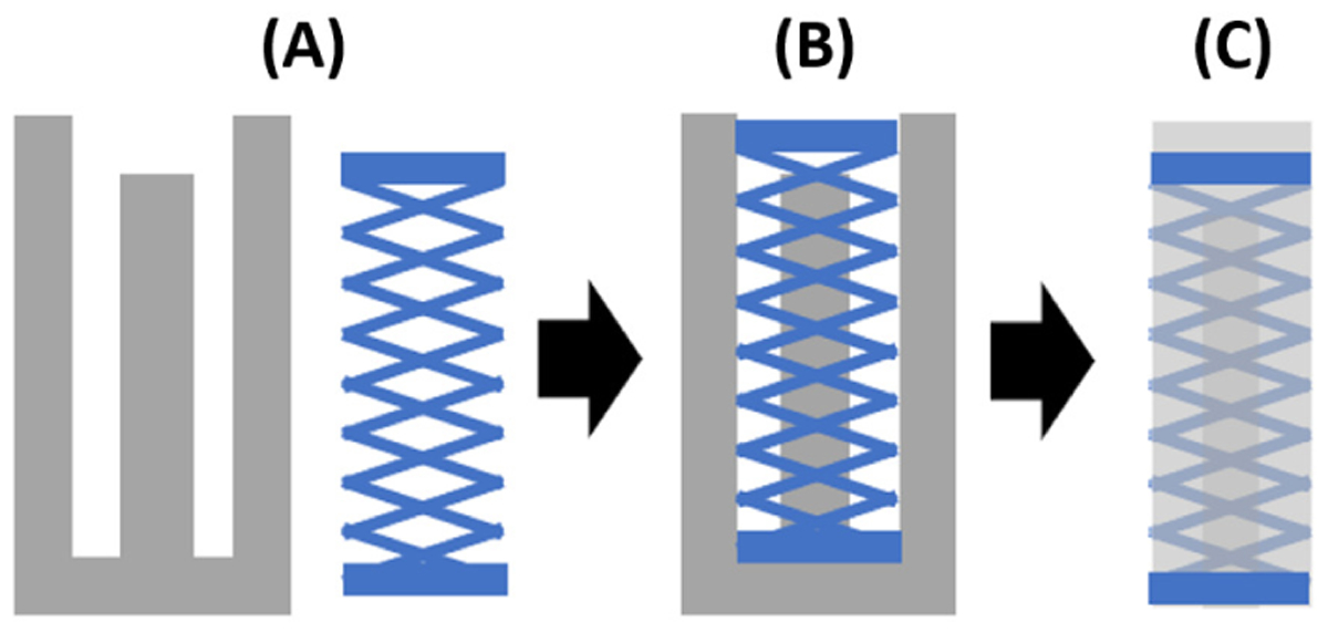
Molding process steps: (A) Mold and internal structure; (B) internal structure is inserted into the mold and silicone is poured in, and (C) the molded FEA is taken out of the mold.
III. DAS-PER Modeling
A significant benefit of the proposed DAS-PER is its tunability. Design parameters of DAS-PER’s internal structure such as segment thickness can easily be modified to approach the desired actuation behavior for the particular application. To maximize the benefits of tunability, a high fidelity model is also needed to avoid the inefficient trial-and-error-based tuning procedures with numerous time-consuming physical trials. The proposed model enables deterministic model-based design of the DAS-PERs. This section discusses a comprehensive modeling approach that effectively can reflect fabricated DAS-PER’s actuation behaviors in both bending and elongation. Following assumptions were made in modeling DAS-PER: (1) Radial and circumferential stresses are counteracted by the internal structure and thus are vanishing, which is nearly always assumed by researchers when modeling bending of radially constrained PERs [5]; (2) DAS-PER’s shapes follow a constant curvature (i.e., bending radius and angle can define the robot’s shape), allowing for simplified and accurate representation of the robot’s state [18]; (3) Internal structure has a constant (Hookean) stiffness, which has been validated by the later experiments; (4) Silicone acts as an hyperelastic neo-Hookean solid; and (5) Silicone displacement can be modeled as displacement of a hollow cylinder with the thickness of the internal structure. These assumptions were used to derive governing equations for the internal structure (Section III.A) and the silicone layer (Section III.B) separately. DAS-PER model (Section III.C) combines these equations by assuming coupled deformation (i.e., the internal structure and the silicone layers stay together as they bend and extend).
A. Quad-helical Internal Structure Modeling
To analytically design and tune the stiffness of the internal structure presented in Fig. 2, a model based on Castigliano’s method [19] was formulated. The total axial deformation of the elastic internal structure was calculated based on the partial derivatives of its strain energy. Of note, this calculation depends on the internal structure design parameters (i.e., length, diameter, and double helix geometry of the internal structure), as well as the exerted axial force. As shown in Fig. 2, the internal structure is constructed by repeating a segment depicted in Fig. 4C. The mechanics of the flexible internal structure, therefore, was evaluated by analyzing the repeated segment between two connecting points, where one end of the segment is anchored to the other segments. The overall energy of the structure is the linear combination of the associated energy with each of these segments. Thus we begin with modeling the individual segments to later combine it into the model of the full internal structure. Following the Castigliano’s Method [19], the strain energy of an internal structure segment is the following:
| (1) |
where M1, M2, and To are the internal moments and torque of the structure, respectively (Fig 4). Angle α represents the segment angle (Fig. 2) and θ defines the helical angle offset (Fig. 4). E is Young’s modulus. I1 and I2 are the second moments of area of the cross-section, and RIS is the radius of the internal structure. G is shear modulus and J is the second moment of area around its origin. Since the cross-section of the the coils are circular and symmetric, future notations will use I to denote both I1 and I2. Of note, in each segment, the joint/point at which To, Co and Mo are acting on is considered to be grounded (Fig. 4) i.e.:
| (2) |
Considering (1) and (2), the internal structure’s single segment deflection Δ can be computed by derivation of the strain energy with respect to the applied axial force V (shown in Fig. 4). It is worth noting that the internal moments and torque expressed in (1) are a function of the axial applied force to the segment:
| (3) |
Based on Fig. 4, the total moment around the z-axis is set to zero (i.e., equilibrium conditions) and the resulting relation is the following:
| (4) |
Fig. 4.

Top view of internal structure division into the repeated segments used for Castigliano’s Method analysis. The segment extends 90 degrees from the top view as it connects from one joint to the next. P, Mo, To and, Co are the reaction forces from the grounding joint.
Similarly, the sum of the moment around and r coordinates (ΣMr) shown in Fig. 4 can be computed as:
| (5) |
| (6) |
From (3), M1 can be calculated:
| (7) |
Also, from (1) and (2), T and M2 can be obtained:
| (8) |
| (9) |
Equilibrium conditions in the cylindrical coordinate system defined by (4)–(6) yield the components of the geometry-based relationships (7)–(9). Additionally, with the boundary conditions defined in (2), (1) can be fully defined. Furthermore, as a result of (3), deformation of a single segment in a DAS-PER internal structure can be characterized. To calculate the overall strain energy of the internal structure, the analysis of a single segment has to be scaled up to the full internal structure. The internal structure has morphological symmetry in the front and side planes (Fig. 2). When the internal structure is cut through any plane parallel to the top plane, there are always four segments exposed. This observation along with the internal structure’s symmetry means that each segment carries an equal share of the load applied in equilibrium. Hence, let denote the force applied to the overall core structure, the relationship between P and can be obtained as the following:
| (10) |
where q denotes the number of segments of interest in the same joint-layer. For example, q can be set to 4 when working with symmetric internal structures to find the overall stiffness. In cases the internal structure is asymmetric, q can be set as 2 to find the half side’s stiffness. The segments’ deformation also adds to each other for every joint-layer. Then, if is the deflection of the overall core structure and n is the number of joints down one side of the structure, the relationship between Δ and can be computed as:
| (11) |
Considering (10) and (11), the axial stiffness, of the core structure can be determined as:
| (12) |
The model of the internal structure directly relates design parameters to stiffness. Internal structure’s stiffness relates negatively with segment thickness (d1, d2), overall radius (RIS) and segment numbers(n). Internal structure’s stiffness relates positively with segment angles (α).
B. Neo-Hookean Silicone Model
To model deformation behavior of the DAS-PER’s silicon structure, we use incompressible Neo-Hookean theory [20]. The theory defines strain energy W as the following:
| (13) |
where C1 is a material constant defined as part of the overarching Ogden material theory and I1 is the trace of the Cauchy-Green deformation tensor such that
| (14) |
where tr(.) denotes trace of a matrix, F defines the deformation tensor, and λ1, λ2, λ3 represent the principal stretches in axial, radial and circumferential directions, respectively. Following the aforementioned assumption of vanishing radial and circumferential stress, the axial principal stress of interest can be formulated as a partial derivative with respect to the axial principal stretch [5]:
| (15) |
where p is a Lagrange multiplier.
C. Modeling DAS-PER’s Bending and Elongation Motion
Assuming moment and force equilibrium, the equations that must be solved to find the shape of the robot are:
| (16) |
where Mapplied and Minternal represent the applied moments and the internal reaction moments respectively. Similarly, Fapplied and Finternal represent the applied and internal reaction forces respectively. Due to symmetry of pressure forces around the center plane of the DAS-PER, ∑ Mapplied = 0. Then, the moment equilibrium condition can be simplified to:
| (17) |
Let ψ and Rb define the bending angle and the bending radius, respectively, as shown in Fig 5. By the geometry of DAS-PER, the axial principal stretch can be defined as:
| (18) |
where ψ is the bending angle, Rb is the bending radius, and L is the original length of the robot. Because neither side of DAS-PER is fully strain-limited, the principal stretch definition cannot be further simplified by a constant geometric relationship between Rb and ψ. In planar actuation, the principal stretch is constant along the same distance d away from the neutral plane as observed in Fig. 5. Therefore, with the known axial Neo-Hookean stress definition of (15), stress σd given actuation shape Rb and ψ at d distance away from the neutral plane can be obtained by:
| (19) |
Fig. 5.

DAS-PER’s Bending and elongation model parameters. Constant curvature modeling simplifies the shape to completely be defined using two parameters i.e., bending radius (Rb) and bending angle (ψ).
Resulting from geometry and integrating stress over the circular cross section, the internal force Fr and moment Mr on the center plane from silicone cylinder of radius r can be obtained as follows:
| (20) |
where fr is the distributed projection of the silicone reaction force (Fig. 5). Of note, from now on, the subscripts for Fr and Mr will define the limits of integration from −r to +r in general. Additionally, the internal structure applies force and moment on the distal end. With assumption (1), the force and moment applied on the distal cap is linear with the axial principal stretch. To account for asymmetry, let define the axial stiffness of half of an asymmetric internal structure with overall radius of RIS found from (12). Then, the force Vk and moment Tk applied by a half internal structure on the distal cap can be calculated as the following:
| (21) |
By observing the DAS-PER’s structure outlined in Fig. 5 and the assumptions of tubular displacement of silicone by the internal structure, the internal force ∑ Finternal and moments ∑ Minternal applied by the silicone and internal structure can fully be defined as:
| (22) |
where, as shown in Fig. 5, tis represents the thickness of the internal structure and ro, ri, and rs are the DAS-PER’s outer and internal radii, and the internal structure’s midline radius, respectively. Also, Vk1 and Vk2 denote internal structure reaction forces below and above the neutral axis, respectively. Similarly, Tk1 and Tk2 define internal structure reaction positive and negative moments on the distal cap, respectively from (21). To solve for the equilibrium conditions (16), the applied force must be also assessed. Assuming the only significant applied force component comes from the pressure acting on the distal cap, it can be found as:
| (23) |
where, as shown in Fig. 5, fPin is the projection of the distributed pressure to the DAS-PER’s bending plane. Pin and Patm represent the input and atmospheric pressure acting on the robot, respectively. Also, is the distal cap area. Applying the results of (17), (22) and (23) to the original equilibrium conditions (16), the bending radius and angle can be solved based on the design parameters.
IV. Experimental Studies
A. Experimental Setups and Procedures
To evaluate the performance of the developed modeling approach as well as the fabricated internal structure and DAS-PER, two experimental setups have been designed. The following sections briefly describe these experiments.
1). Axial Stiffness Testbed to Evaluate Internal Structure’s Stiffness Model:
A single degree of freedom testbed was prepared to find the axial stiffness of the internal structure and compare the obtained experimental result with the calculated stiffness using the Castigliano’s method described in Section III.A (Fig. 6). To perform the experiments, a digital caliper was connected to the the force gauge (DFG55, Omega Engineering) in order to measure displacement and force in the axial direction, respectively. The printed internal structure was fixed on one end and connected to a linear carriage stage on the other. The internal structure was then pulled at 5 mm increments up to 30 mm by a stepper motor-actuated linear stage (BE069-6, Befenybay). The average gradient in the linear region of the force-elongation plots of five trials was taken as measured stiffness. To demonstrate practical efficacy of the proposed modeling approach, three different stiffness values were set then the model was used to design the internal structure to match the stiffness. It was determined with the model that to achieve stiffness of 5 N/m, 25 N/m and 125 N/m, the SLA Flexible Resin internal structures should have the diameters of 0.74 mm, 1.11 mm and 1.66 mm respectively (Table II). The angle of the analyzed segment with respect to the ground axis (i.e., α) was taken as 15°. Integration in (1) was taken from 0 rad to . The radius of the internal structure was considered as 5.0 mm as designed. The samples were prepared with 10 joints along one side (i.e., n=10).
Fig. 6.

Axial stiffness testbed: the internal structure samples were mounted and pulled. The reactive force was measured using the load cell and the data was used to measure the internal structure’s stiffness.
TABLE II.
Comparison of the experimental results to the model
| Material | kd | Dm | km | Error |
|---|---|---|---|---|
| FR | 5 N/m | 0.74 mm | 5.52 N/m | 10.40% |
| FR | 25 N/m | 1.11 mm | 22.6 N/m | 9.6% |
| FR | 125 N/m | 1.66 mm | 109.66 N/mm | 12.27% |
FR: Flexible Resin; kd:Desired Stiffness from Model; Dm: Coil Diameter; km:Obtained Experimental Stiffness;
Fig. 8 shows the obtained experimental elongations versus exerted forces using the stiffness testbed for the three considered internal structures. The shaded region around each plot denotes the deviation of the 5 trials from the calculated average. The observed deviations for samples of kd = 5 N/m and kd = 25 N/m were ≤ 0.02 N and thus are not visible in the figure. Table II summarizes the comparison of the calculated stiffness based on the model and obtained experimental results. The input parameters into the derived model were held constant among the tested internal structure except for the cross-sectional diameter. The material properties and their corresponding parameter values are stated in Table I. Additionally, to find material constant C1 based on the Ogden axial elongation equation [21], the same experiment was conducted with a cylindrical-shape silicone sample with cross-sectional area and length of 250 mm2 and 42 mm, respectively. Fig. 8 also includes the force-elongation profile of this experiment. Based on the obtained data, the material constant C1 to be used in (15) was found to be 10.6 kPa with R2 value of 0.998.
Fig. 8.

The experimentally-obtained relationship between elongation of DAS-PER’s components (internal structure and silicone separately) and reaction force resisting elongation. The shaded regions denote the repetitions of experimental trials. Note that the samples with desired stiffness (kd) of 25 N/m and 125 N/m had deviations among trials of less than 0.02N.
2). Actuation Testbed to Evaluate DAS-PER’s Model:
Two different DAS-PERs were fabricated and tested to assess the model’s ability to predict their actuation behavior. The design parameters of these DAS-PERs were selected to display different extension and bending behaviors. First robot (i.e., DAS-PER A) was embedded with an internal structure that had 1.5 mm and 2.0 mm helices. Second robot (i.e., DAS-PER B) had an internal structure with 1.0 mm and 2.0 mm helices. In reference to Fig. 2, Ris, tis, α were designed to be 7.5 mm, 2 mm and 15°, respectively. In reference to Fig. 5, L, ri and ro were designed to be 50 mm, 4.5 mm, and 10 mm, respectively, for both samples.
As shown in Fig. 7, sample DAS-PERs were secured on a controlled testbed. A pneumatic diaphragm pump (D028B, Airpo™), a solenoid valve (USS2-00005, U.S. Solid), a pressure sensor (SSCDANT150PGAA5, Honeywell International Inc.), and the DAS-PER were connected. A microcontroller was used to control the pump and the valve. Three red markers were placed along the DAS-PER sample to detect the actuated shape. The three markers on DAS-PER also allows us to validate the constant curvature assumption made in the modeling steps. Three additional red markers were placed on the base 3 cm from each other to define the axes and scale. The data from an RGB camera was then processed using the MATLAB Computer Vision Toolbox to find relative positions of the markers. Pressure was increased incrementally by 10 kPa from 0 kPa to 80 kPa. There was a 5 second delay at each pressure for the DAS-PER settle into an equilibrium state.
Fig. 7.
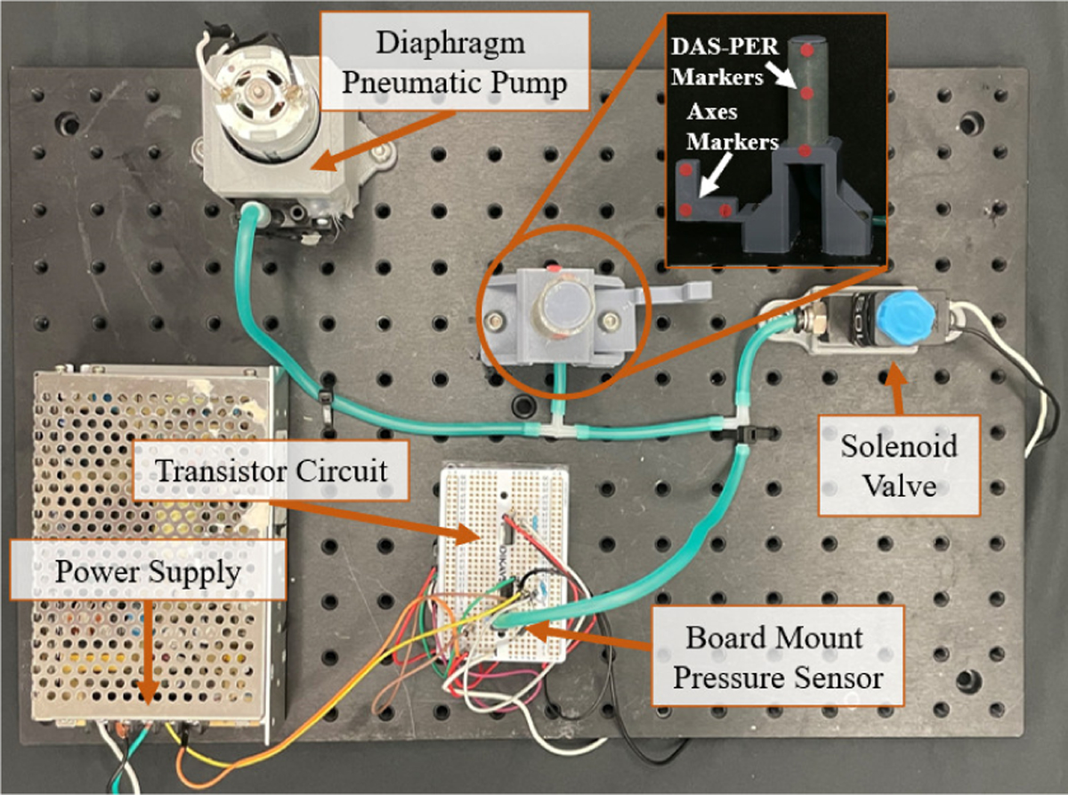
Experimental setup for validating actuation behavior model of the fabricated DAS-PERs.
The actuation profiles of the PERs are plotted in Fig. 9. Three points on the DAS-PER samples were plotted at 60 kPa, 70 kPa and 80 kPa internal pressure and a constant curvature line was fitted on each experiment. These plots were overlaid with model predictions. The figure also includes images that were processed to obtain the results.
Fig. 9.

DAS-PERs’ actuation results for 20 kPa, 40 kPa, 60 kPa, 70 kPa, and 80 kPa compared against the model predictions. DAS-PER A was embedded with a 1.5 mm-2.0 mm asymmetric internal structure. DAS-PER B was embedded with a 1.0 mm-2.0 mm asymmetric internal structure, resulting in different concurrent extension-bending behaviors.
V. Discussion
Our results indicate that the force-elongation profiles of the three internal structures closely follow the model’s assessment of structure stiffness in relation to cross-sectional diameter with Mean Absolute Percentage Error (MAPE) of <12.5% (Fig. 8). The stiffness of the internal structure increases with an increase in cross-sectional diameter in a predictable manner. Large changes in stiffness values could be achieved with relatively small change in diameters. This is partially because the moment of inertia calculations amplify changes in the internal structure’s coil diameter. From Table II, it is also evident that the experimentally obtained stiffness of the internal structures closely matches the calculated stiffness utilizing the Castigliano’s energy method. We have also validated the efficacy of the DAS-PER design and modeling method (Fig 9). The mean absolute tip position error of the DAS-PERs were found to be <5 mm independent of the stiffness scale. The mean percentage error for the model to the observed DAS-PER shape (determined by the fitted curvature) was <12% for the DAS-PER A sample and <18% for the DAS-PER B sample. The strong results underscore not only the efficacy of the modeling but also the reliability of the presented design and fabrication procedure. Furthermore, two observations can be made from the performed experiments. First, despite the relatively small 0.5 mm change in diameter of the internal structure, the bending and extension behavior of the DAS-PER greatly were affected. With the highest internal pressure tested of 70 kPa, the bending radius was increased by 241% from DAS-PER B to DAS-PER A. Secondly, the results also show that the primary mode of deformation changes based on the stiffness difference on each side of the internal structure. When the difference is large such as with DAS-PER B configuration, actuation behavior is dominated by bending. When the difference is smaller such as with the DAS-PER A configuration, the actuation behavior is dominated by extension. We may observe these behavior differences in Fig. 9. Of note, the maximum observed radial strain was 3.27% at 80 kPa with DAS-PER sample B, validating the assumption (1) of Section III. Furthermore, two observations can be made from the performed experiments. First, despite the relatively small 0.5 mm change in diameter of the internal structure, the bending and extension behavior of the DAS-PER greatly were affected. With the highest internal pressure tested of 80 kPa, the bending radius was increased by 241% from DAS-PER B to DAS-PER A. Secondly, the results also show that the primary mode of deformation changes based on the stiffness difference on each side of the internal structure. When the difference is large such as with DAS-PER B configuration, actuation behavior is dominated by bending. When the difference is smaller such as with the DAS-PER A configuration, the actuation behavior is dominated by extension. Of note, in both cases, DAS-PER actuation behavior displayed little to no observable ballooning effect or changes in the overall diameter. Furthermore, because the bending and extension behaviors can be concurrently tuned by varying internal structure helix thicknesses, the proposed DAS-PER design does not suffer from the trade-off between actuation behavior tunability and radial restraint such as the method noted in [14]. The accuracy of the model and the displayed sensitivity to internal structure design parameters ultimately validate the method’s ability to enable researchers to tune the behavior of PERs to achieve diverse set of concurrent bending and extension profiles. The design and model-based framework presented in this paper can effectively enable PERs to be tuned optimally based on the application in hand.
The free-standing 3D printed internal structure enabled single step molding of DAS-PER, eliminating unnecessary curing time. The fabrication procedure does not depend on the skill or intuition of the fabricator with approximately 30 minutes of active labor involving two mold components. Based on the rough benchmark reported in the literature (e.g., [13]), DAS-PER fabrication approximately represents an 80% reduction in mold parts compared to single chamber PERs and about an 50% reduction in active labor time. The simpler fabrication procedures not only shorten fabrication time but they also enable reliable realization of desired actuation behaviors.
VI. Conclusion
We presented a novel comprehensive method that integrates analytical modeling and additive manufacturing-based fabrication, for designing PERs that can concurrently bend and extend. Experimental results with DAS-PER confirmed that axial stiffness of the internal structures can be accurately modeled using the proposed energy-based mechanics approach developed through Castigliano’s method and simplified equation for axial loading. Experimental results also validated that the presented actuation model can accurately reflect the DAS-PER’s deformation behavior (i.e., both extension and bending). The presented DAS-PER achieves three key features that are desirable from PERs for operating effectively in a confined environment: (i) elimination of the need for an intermediate molding step for weaving in the fiber thus reducing the active fabrication labor time by 50%; (ii) achievement of significant and concurrent deterministic bending and extension behaviors that are necessary to navigate through and operate in confined spaces; and (iii) excellent deterministic tunability to a variety of desired behaviors, which is characterized by small changes in the internal structure design parameters translating to significant actuation behavior changes.
The unique adjustability of the internal structure can be further explored to yield interesting behaviors of multiple DAS-PERs connected in series. As shown in Fig. 1, the stiffness tunability of the DAS-PERs directly validates their different responses to identical pressure. Therefore, a potential extension of this work would be to experimentally validate the presented model when scaled to a multi-segment system with multiple DAS-PERs. Moreover, a computationally light model of such systems will be developed and compared against finite element analysis (FEA) results in our future studies.
Fig. 1.

(A) Asymmetric internal structure with different directional biases to realize distinct actuation behaviors; (B) Unactuated Deterministically Adjusted Stiffness-Pneumatic Elastomer Robot (DAS-PER); and (C) Actuated DAS-PER at 80 kPa. Note that the upper half of the DAS-PER displays a smaller bending radius than the bottom half from the larger directional bias in the internal structure.
Supplementary Material
Acknowledgments
Research reported in this publication was partially supported by the National Institute of Biomedical Imaging and Bioengineering of the National Institutes of Health under Award Number R21EB030796 and the University of Texas at Austin internal funds.
REFERENCES
- [1].Cao L, Li X, Phan PT, Tiong AMH, Liu J, and Phee SJ, “A Novel Robotic Suturing System for Flexible Endoscopic Surgery,” in 2019 International Conference on Robotics and Automation (ICRA), May 2019, pp. 1514–1520. [Google Scholar]
- [2].Kamata M, Yamazaki S, Tanise Y, Yamada Y, and Nakamura T, “Morphological change in peristaltic crawling motion of a narrow pipe inspection robot inspired by earthworm’s locomotion,” Advanced Robotics, vol. 32, no. 7, pp. 386–397, Apr. 2018. [Google Scholar]
- [3].Sedal A, Bruder D, Bishop-Moser J, Vasudevan R, and Kota S, “A Continuum Model for Fiber-Reinforced Soft Robot Actuators,” Journal of Mechanisms and Robotics, vol. 10, no. 024501, Feb. 2018. [Google Scholar]
- [4].Marchese AD and Rus D, “Design, kinematics, and control of a soft spatial fluidic elastomer manipulator,” The International Journal of Robotics Research, vol. 35, no. 7, pp. 840–869, Oct. 2015. [Google Scholar]
- [5].Polygerinos P, Wang Z, Overvelde JTB, Galloway KC, Wood RJ, Bertoldi K, and Walsh CJ, “Modeling of Soft Fiber-Reinforced Bending Actuators,” IEEE Transactions on Robotics, vol. 31, no. 3, pp. 778–789, June 2015. [Google Scholar]
- [6].Hashemi S, Bentivegna D, and Durfee W, “Bone-Inspired Bending Soft Robot,” Soft Robotics, July 2020. [DOI] [PMC free article] [PubMed] [Google Scholar]
- [7].Deimel R and Brock O, “A novel type of compliant and underactuated robotic hand for dexterous grasping,” The International Journal of Robotics Research, vol. 35, no. 1–3, pp. 161–185, Aug. 2015. [Google Scholar]
- [8].Suzumori K, Maeda T, Wantabe H, and Hisada T, “Fiberless flexible microactuator designed by finite-element method,” IEEE/ASME Transactions on Mechatronics, vol. 2, no. 4, pp. 281–286, Dec. 1997. [Google Scholar]
- [9].Mosadegh B, Polygerinos P, Keplinger C, Wennstedt S, Shepherd RF, Gupta U, Shim J, Bertoldi K, Walsh CJ, and Whitesides GM, “Pneumatic Networks for Soft Robotics that Actuate Rapidly,” Advanced Functional Materials, vol. 24, no. 15, pp. 2163–2170, 2014. [Google Scholar]
- [10].Shepherd RF, Ilievski F, Choi W, Morin SA, Stokes AA, Mazzeo AD, Chen X, Wang M, and Whitesides GM, “Multigait soft robot,” Proceedings of the National Academy of Sciences, 2011. [DOI] [PMC free article] [PubMed] [Google Scholar]
- [11].Connolly F, Walsh CJ, and Bertoldi K, “Automatic design of fiber-reinforced soft actuators for trajectory matching,” Proceedings of the National Academy of Sciences, vol. 114, no. 1, pp. 51–56, 2017. [DOI] [PMC free article] [PubMed] [Google Scholar]
- [12].Connolly F, Polygerinos P, Walsh CJ, and Bertoldi K, “Mechanical Programming of Soft Actuators by Varying Fiber Angle,” Soft Robotics, vol. 2, no. 1, pp. 26–32, Mar. 2015. [Google Scholar]
- [13].Fras J, Glowka J, and Althoefer K, “Instant soft robot: A simple recipe for quick and easy manufacturing,” in 2020 3rd IEEE International Conference on Soft Robotics (RoboSoft), July 2020, pp. 482–488. [Google Scholar]
- [14].Wang Z, Polygerinos P, Overvelde JTB, Galloway KC, Bertoldi K, and Walsh CJ, “Interaction Forces of Soft Fiber Reinforced Bending Actuators,” IEEE/ASME Transactions on Mechatronics, vol. 22, no. 2, pp. 717–727, Apr. 2017. [Google Scholar]
- [15].Ellis DR, Venter MP, and Venter G, “Soft Pneumatic Actuator with Bimodal Bending Response Using a Single Pressure Source,” Soft Robotics, Aug. 2020. [DOI] [PubMed] [Google Scholar]
- [16].Nakajima T, Yamaguchi T, Wakabayashi S, Arie T, Akita S, and Takei K, “Transformable Pneumatic Balloon-Type Soft Robot Using Attachable Shells,” Advanced Materials Technologies, vol. 5, no. 7, p. 2000201, July 2020. [Google Scholar]
- [17].Huy Nguyen P, Sridar S, Zhang W, and Polygerinos P, “Design and control of a 3-chambered fiber reinforced soft actuator with off-the-shelf stretch sensors,” International Journal of Intelligent Robotics and Applications, Apr. 2017. [Google Scholar]
- [18].Polygerinos P, Correll N, Morin SA, Mosadegh B, Onal CD, Petersen K, Cianchetti M, Tolley MT, and Shepherd RF, “Soft Robotics: Review of Fluid-Driven Intrinsically Soft Devices; Manufacturing, Sensing, Control, and Applications in Human-Robot Interaction,” Advanced Engineering Materials, vol. 19, no. 12, p. 1700016, Dec. 2017. [Google Scholar]
- [19].Beer F, Johnston E Jr., DeWolf J, and Mazurek D, Mechanics of Materials. McGraw-Hill Education, 2011. [Google Scholar]
- [20].Gwinner J, “Non-linear elastic deformations,” Acta Applicandae Mathematica, vol. 11, no. 2, pp. 191–193, Feb. 1988. [Google Scholar]
- [21].Ogden RW, Saccomandi G, and Sgura I, “Fitting hyperelastic models to experimental data,” Computational Mechanics, vol. 34, no. 6, pp. 484–502, Nov. 2004. [Google Scholar]
Associated Data
This section collects any data citations, data availability statements, or supplementary materials included in this article.