Abstract
Objective:
To quantify the influence of temporary anchorage device (TAD) insertion variables on implant retention.
Materials and Methods:
Three hundred thirty TADs from three companies were placed in synthetic bone replicas at variable depths and angulations and compared. Clinically relevant forces were applied to the TADs until failure of retention occurred.
Results:
In all three implants, increased insertion depth increased implant retention. As the distance from the abutment head to the cortical plate increased, the retention of all three implants decreased. A significantly greater force to fail was required for a 90° insertion angle than for 45° or 135° insertion angles. No significant difference was found between the 45° and 135° insertion angles. A significant reduction in force to fail occurred when comparing 90° and 45° oblique insertion angles.
Conclusions:
Increasing penetration depth of TADs results in greater retention. Increased abutment head distance from cortical plate leads to decreased retention. Placement of TADs at 90° to the cortical plate is the most retentive insertion angle. Insertion at an oblique angle from the line of force reduces retention of TADs.
Keywords: Temporary anchorage device, Mini-implant, Implant failure, Implant retention, Bone, Force to fail
INTRODUCTION
For more than 100 years, orthodontists have searched for ideal anchorage that fits two criteria: absolute resistance to unwanted tooth movement and independence from patient compliance. Conventional intra- and extraoral anchorage systems often fall short of providing absolute anchorage. This deficiency has spurred interest in skeletal anchorage systems, which appeal to practitioners because they have the potential to provide absolute anchorage and do not depend on patient compliance.1 Skeletal anchorage has been the subject of study for more than 60 years in orthodontics.2,3 The successful use of osseointegrated retromolar, palatal, and restorable implants has been demonstrated in the literature.4–6 Unfortunately, these implant systems require osseointegration before orthodontic force can be applied; in addition, they may increase treatment time, they are expensive, their size limits placement location, and their removal is difficult.
Unlike osseointegrated implants, temporary anchorage devices (TADs) are easily inserted and removed, and can be immediately loaded.1,7 They are relatively inexpensive and can be placed in a variety of locations, vastly increasing their versatility.1 Consequently, TADs are quickly becoming the preferred method of skeletal anchorage. The risk and utility of TADs are questions that still need to be answered. Since TADs are not osseointegrated, the magnitude of orthodontic forces they can withstand, and how various insertion parameters affect their ability to withstand these forces is not well understood.
Reported success rate of TADs ranges from 80.5% to 95.2%.1,7–9 Implant diameter, length, time of loading, and presence of inflammation have been reported as factors affecting success of TADs.1,7–9 Implant retention is also affected by loading parameters. Previous studies have employed direct pull-out tests with forces running parallel to the long axis of the TAD.10 Because TADs are not loaded vertically in clinical situations, a more appropriate model is to load TADs perpendicular to their long axes, placing horizontal forces on the implants.
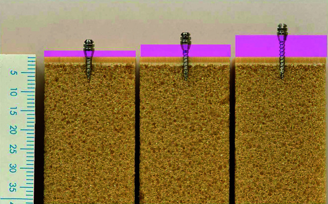
Previous reports suggest greater moment arms created by increased abutment head distance from the cortical plate reduce implant stability.11 Investigations have been limited to minimal variations of abutment head distance from the cortical plate and are not well correlated to the clinical environment.12 As soft tissue thickness for TAD placement may be as high as 4.5 mm, implants seated to the soft tissue collar potentially create increased lever arms, which affect stability9,13–15 (Figure 1). These features and their potential impact on TAD placement and stability require further investigation.
Figure 1.
Soft tissue difference effects on implant insertion.
Previous reports on the potential impact of insertion angles on retention are conflicting. Published reports have recommended insertion angles of 45°, while others advise that a 90° angle to the cortical plate is more retentive (Figure 2).1,16 To date, reviews on the impact of loading implants obliquely when inserted at extreme angles to the occlusal plane have not been evaluated. With such wide variation in advice, it is difficult to determine best-evidence clinical guidelines. Moreover, studies evaluating the potential impact of insertion angles define TAD failure differently. Some investigations have defined failure as complete removal, while others are less stringent.
Figure 2.
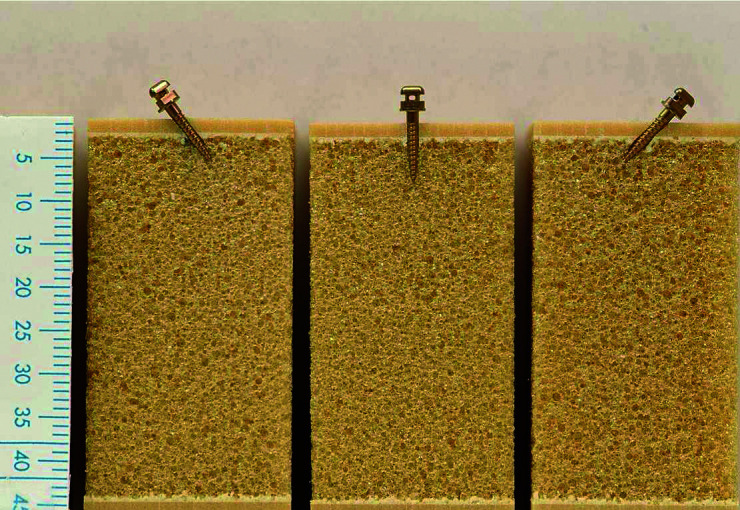
Angular insertion of 45°, 90°, and 135° to the cortical plate.
The purpose of this study was to investigate insertion variables and their affect on TAD stability. Variables included penetration depth, angle of insertion, and attachment head distance from the cortical plate.
MATERIALS AND METHODS
Three hundred thirty tests were completed on TADs of three companies: Ormco, Orange, CA; Synthes North America, West Chester, PA; and Dentaurum, Newtown, PA. Implants were placed in synthetic bone replicas (Sawbones, Pacific Research Laboratories) and matched for cortical plate and cancellous bone thickness and density of the maxillary premolar region. Self-drilling TADs, which included Ormco VectorTAS, 6 mm and 8 mm; Synthes OBA (Orthodontic Bone Anchor), 6 mm, 8 mm, and 10 mm; and Dentaurum tomas (temporary orthodontic micro anchorage system), 6 mm, 8 mm, and 10 mm, were tested. TADs from three different companies were used, not to test differences between products, but to study how TADs respond overall to specific placement protocols.
Synthetic bone replicas were matched for the maxillary premolar region in cortical plate thickness, as well as plate and cancellous bone densities.17–19 The maxillary premolar region was selected due to its combination of the thinnest cortical plate, the least dense cancellous bone and because clinically, it represents a common location for TAD placement.17–19
Biomechanical test blocks were chosen over a cadaver model because they offer uniform and consistent physical properties that eliminate the variability encountered when testing with human cadaver bone. Synthetic bone also does not have the concerns of desiccation and quality change of cadaver bone. Bone blocks consisted of a cancellous region of 0.08 g/cc (5 pcf) density cellular rigid polyurethane foam with a 1.5 mm 0.64 g/cc (40 pcf) laminated solid rigid polyurethane foam cortical plate analog. Blocks were milled to 1 inch2 by 1.8 inches tall.
The ability of each TAD to resist increasing force levels was evaluated for three separate insertion variables: insertion depth, abutment head from the cortical plate, and angle of insertion. For evaluation of insertion depth, implants were inserted 90° to the cortical plate to the depth of the soft tissue collar creating 6-, 8-, and 10-mm insertion depths, respectively (Figure 3). For evaluation of abutment distance from the cortical plate, all implants were inserted to a uniform 6-mm depth. Implants of 6 mm were inserted to depth, leaving a 4-mm abutment head above the cortical plate. Implants of 8 mm and 10 mm were inserted to 6-mm depths, leaving their abutment heads and additional threads above the cortical plate, creating increased abutment head distances from the cortical plate (Figure 4). An additional investigation of distance from the cortical plate was undertaken, inserting 10-mm implants to a depth of 8 mm, creating a 6-mm distance from the cortical plate. This was compared to 6-mm and 8-mm implants inserted to depths of 6 mm, creating 4- and 6-mm abutment distances from the cortical plate, respectively (Figure 5).
Figure 3.
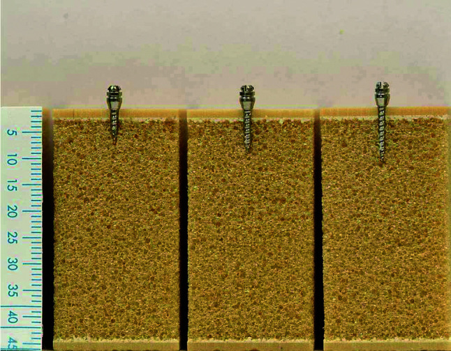
Implants of 6 mm, 8 mm, and 10 mm inserted to base of soft tissue collar.
Figure 4.
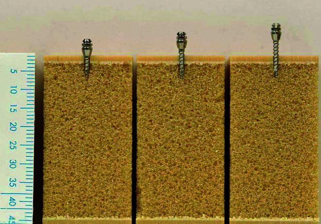
Abutment distances from the cortical plate.
Figure 5.
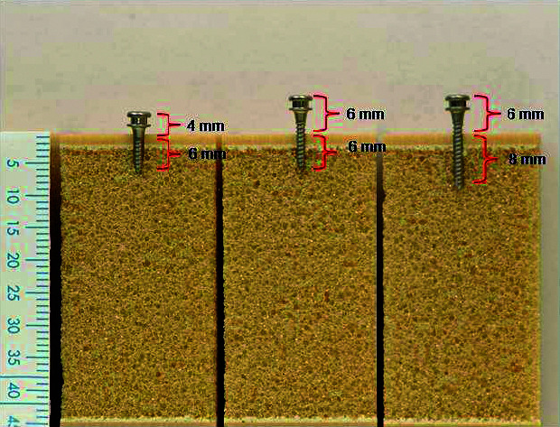
Abutment distance from the cortical plate deep insertion.
Effects of insertion angle were also investigated, inserting 8-mm implants at 45°, 90°, and 135° angles to the cortical plate. Each of the three angular placements was made in the same plane as the line of force applied. A final angular test was completed placing the implants perpendicular to the applied force, but at a 45° oblique angle (Figure 6). A custom jig was designed to ensure all implants were inserted at the appropriate angle.
Figure 6.
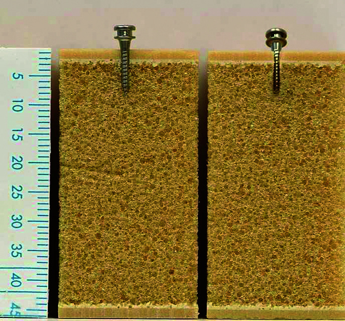
Angular oblique insertion.
A small-scale loading machine (Figure 7) was used to apply force to the implants. Bone blocks were placed in the machine with the implants oriented tangent to the load cell secured with vise grips and a backing plate to counteract block rotation. Implants were attached via a .30-mm monofilament nylon ligature looped around the abutment head and attached to a 10-lb load cell via a compression grip. Force was applied to the implants at a rate of 4 mm/sec until failure of retention occurred. Failure point was determined at the inflection point, the point beyond bending at which the implant initially began to move in the bone block (Figure 8). Ten data points were collected per second and the load displacement data were recorded. Peak load force to fail was obtained. Force to fail was analyzed by using unpaired t-tests for two group comparisons and one-way analysis of variance (ANOVA) for three or more comparison groups. Post-hoc analyses used the Tukey-Kramer method. Results were considered significant at P < .05.
Figure 7.
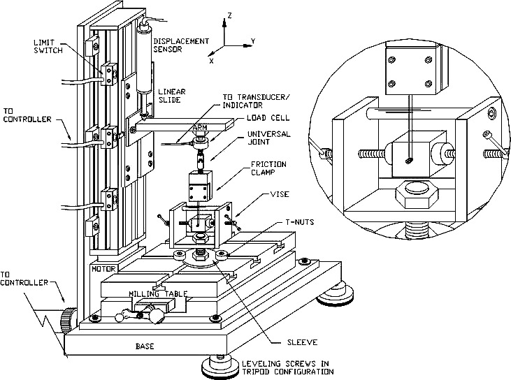
Small scale loading machine with a blowup of bone blocks placed in the machine with the implants oriented tangent to the load cell.
Figure 8.
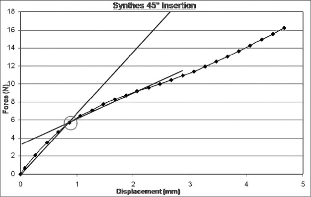
Test demonstrating failure point determined via inflection point indicating translation of implant in bone block.
RESULTS
The initial force to fail tests on 330 implants was successfully recorded. Significant differences (P < .05) in force to fail were detected in all groups examined.
Insertion Depth
In all three implant systems, a significant increase in force to fail occurred as insertion depth increased (P < .001; Figure 9; Table 1). The force to fail required for all 6-mm penetration depths was significantly less than that for 8-mm depths. There were no significant differences between the 8-mm and 10-mm insertion depths. Reduction in force to fail was 25.0% (P < .05) for Ormco VectorTAS 6-mm vs 8-mm insertion depths, 17.0% (P < .01) for Synthes OBA 6-mm vs 8-mm, 21.8% (P < .001) for Synthes OBA 6-mm vs 10-mm, 34.1% (P < .01) for Dentaurum tomas 6-mm vs 8-mm, and 36.5% (P < .001) for Dentaurum tomas 6-mm vs 10-mm insertion depths.
Figure 9.
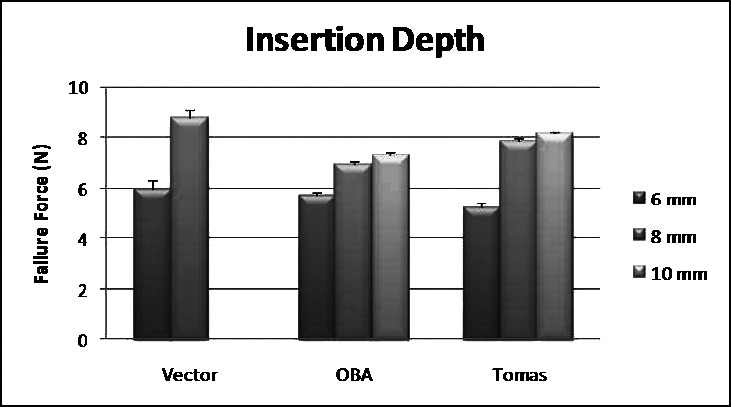
Failure loads for insertion depths.
Table 1.
Failure Loads (in Newtons) for Insertion Depths for Ormco Vector, Synthes OBA, and Dentaurum Tomas Systems
Abutment Distance From Cortical Plate
In all three implant systems, a reduction in force to fail occurred as distance from the cortical plate increased (Figure 10; Table 2). The results for the VectorTAS implants demonstrated a reduction in force to fail when comparing 6-mm and 4-mm distances from the cortical plate, but were not significant due to increased variability in the sample (P > .05). The Synthes OBA demonstrated significant differences between abutment head distances from the cortical plate when comparing 4-mm to 6-mm distances and 4-mm to 8-mm distances. No significant difference in force to fail was found between abutment head distances of 6 mm and 8 mm. In the Synthes OBA, the 6-mm abutment distance from the cortical plate required 24.7% less force before initial failure than the 4-mm abutment distance (P < .05). The 8-mm abutment distance from the cortical plate required 31.4% less force before initial failure than the 4-mm abutment distance (P < .001). The Dentaurum tomas implant demonstrated significant reduction in force to fail with a 24.2% decrease (P < .001) as distance of the abutment head from the cortical plate increased from 4 mm to 8 mm. Results were not significant when comparing abutment distances of 6-mm and 8-mm from the cortical plate. When evaluating increased insertion depth combined with increased abutment distance from the cortical plate, no significant differences in implant retention were found in either the Synthes OBA or the Dentaurum tomas implant systems (Figure 11; Table 3).
Figure 10.
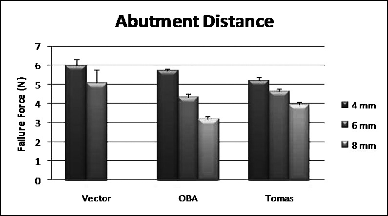
Failure loads for abutment distances from the cortical plate.
Table 2.
Failure Loads (in Newtons) for Abutment Distances From the Cortical Plate for Ormco Vector, Synthes OBA, and Dentaurum Tomas Systems
Figure 11.
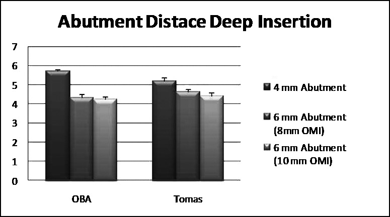
Failure loads for abutment distance from cortical plate deep insertion.
Table 3.
Failure Loads (in Newtons) for Abutment Distance From Cortical Plate with Deep Insertion
Angular Measures
A significantly reduced failure force was required with implants placed at 45° or 135° insertion angles compared with a 90° insertion angle (P < .001) in all three implant systems. No significant difference was found between the 45° and 135° angles in any implant system (Figure 12; Table 4).
Figure 12.
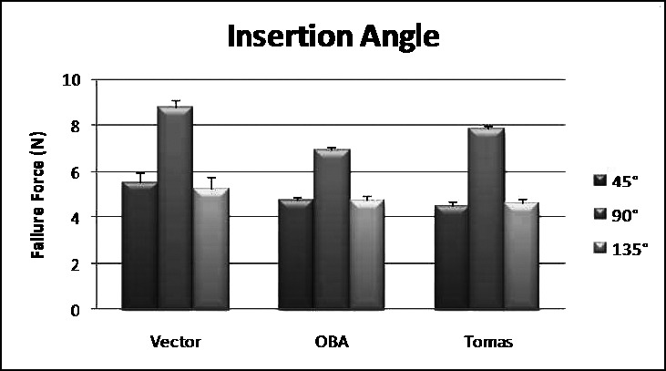
Failure loads for angular insertions 45°, 90°, and 135°.
Table 4.
Failure Loads (in Newtons) for Angular Insertions 45°, 90°, and 135°
Ormco VectorTAS implants placed at 45° or 135° insertion angles to the cortical plate demonstrated 29.6% and 33.3% reduction in force to fail when compared to the 90° insertion (P < .001). No significant difference was found between the 45° and 135° angles. The Synthes OBA also had a significantly reduced force to fail when comparing implants placed at 45° or 135° insertion angles with those placed at a 90° insertion angle (P < .001). These differences represented a 31.5% and 31.9% reduction in force to fail when compared with the 90° insertion, respectively. No significant difference was found between the 45° and 135° angles. The Dentaurum tomas implants placed at 45° and 135° insertion angles had 43.1% and 41.3% reduction in force to fail when compared with the 90° insertion, respectively (P < .001). Again, no significant difference was found between the 45° and 135° angles with the Dentaurum tomas implant.
Angular Oblique
In evaluating the 45° oblique insertion, a significantly reduced force to fail was found when comparing to 90° in all three implant systems (P < .0001; Figure 13; Table 5).
Figure 13.
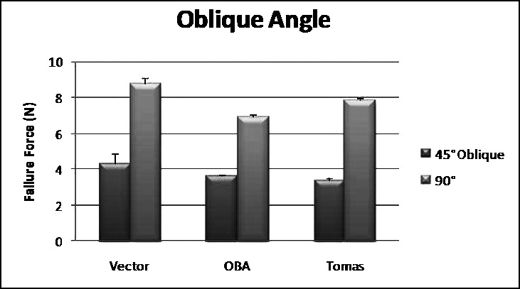
Failure loads for angular insertions 45° oblique and 90°.
Table 5.
Failure Loads for Angular Insertions 45° Oblique & 90° - Ormco Vector, Synthes OBA, and Dentaurum Tomas with Standard Errors.
There was a 45.1% reduction in force to fail from 45° to 90° (P < .0001) using the Ormco VectorTAS system, while there was a 47.8% reduction using the Synthes OBA system (P < .0001). The Dentaurum tomas implant system demonstrated a 45.6% reduction in force to fail (P < .0001) when comparing the 45° oblique and 90° insertion.
DISCUSSION
The results of our study both confirmed and varied from previous reports. Our results confirmed broad clinical interpretations, such as the impact of length on implant success. Our results were also consistent in all three implant systems, demonstrating the results are not TAD specific. Using more clinically relevant definitions of failure, our results refute previous reports of the impact of insertion angle on implant success.16 Our results also confirm the hypothesis of Kyung et al.11 that implant failure increases the further the abutment is from the cortical plate.
As has been shown in previous studies,1,8–10 our study found TAD stability increases with implant length, as long as the increased length is inserted in bone. While implants in this study required more force to fail as the insertion depth increased, the lowest initial failure with a 6-mm implant was 461 grams, well above most traditional orthodontic force levels.20 In applications of high forces (including orthopedic forces) and simultaneous placement of multiple loads on the same implant, longer implants may be necessary for retention. However, in most orthodontic force systems, 6-mm implants appear to be sufficient as long as they are inserted 90° to the cortical plate. Because shorter implants run less risk of damaging roots and their supporting tissues and since they are also likely to withstand most clinical orthodontic force levels, the 6-mm length is appropriate for most applications.
Regarding abutment distance to the cortical plate, our study confirms previous reports on the impact of abutment distance from the cortical plate.13,14 Implant abutments 6 mm from the cortical plate failed at loads as low as 375 grams and those inserted 8 mm from the plate failed at loads as low as 282 grams. With this pattern clearly established in our study, we recommend that implants are inserted so their abutment heads are as close to the cortical plate as possible. Unfortunately, in areas of thick tissue this is not possible and increased torquing arms will be created. Knowing this, we tested if increasing insertion depth would compensate on the occasions where abutment head distance needed to be increased. However, our data do not support a protective component to the increased insertion depth in these situations. Therefore, we cannot suggest that increasing depth of insertion will markedly increase retention in situations where longer torquing arms are required.
The results of our study on the angle of insertion differ from previously published reports.16 Though previous reports have recommended insertion angles with implants angled toward the force acted upon them, our study refutes these findings. In our study, failure of the extreme angles of 45° and 135° was found to occur within orthodontic force levels.20 Our study also showed that 90° insertion to the cortical plate is the most retentive insertion angle, contrary to previously published reports.16 While previous reports found 45° to the force to be the most retentive, failure was determined as total implant pull-out, well beyond the point at which the implant would be of clinical benefit. By defining failure as the point at which the anchor unit begins to move, it is clear a 90° insertion to the cortical plate is the most retentive. Whenever possible, implants should be placed at 90° to the cortical plate for maximum retention.
Oblique angles of 45° to the cortical plate also failed within orthodontic force levels.20 Because this off-axis insertion and load relationship led to significant loss of retention at less than 45%, the amount of force for the 90° insertion angle, this insertion angle is contraindicated when medium to heavy orthodontic force levels are used. Although previous studies recommend inserting implants at an extreme angle to the cortical plate to reduce the risk of root contact on insertion, this recommendation significantly reduces the amount of force the implant will withstand.11 In situations where root proximity is a concern, insertion site should be reconsidered or preimplant orthodontics should be conducted to facilitate root divergence. The results of all angular tests indicate placement of TADs at 90° is suggested for optimal retention.
While the results of this study are definitive, they are not without limitations. This study was conducted with bone analogs and simulated loading. While this design reduces confounding variables, clinical investigation of the principles germane to this study would increase understanding. Readers should also be mindful this study focused on a single insertion location, specifically chosen for the thin cortical plate and least dense cancellous bone of the maxillary premolar region, and did not evaluate the effects of static loading over long-term force application. Future investigations in areas of various hard and soft tissue anatomy are needed. Additionally, evaluations with different implant designs may prove to be beneficial, especially implants with tighter thread patterns and different pitches.
CONCLUSIONS
Increased insertion depth increases retention, though shorter implants should be sufficient in most orthodontic force systems if placed at 90° to the cortical plate.
Increased abutment distance from the cortical plate decreases retention.
Placement at 90° to the cortical plate is the most retentive insertion angle.
Insertion at an oblique angle from the line of force reduces retention.
Acknowledgments
The authors wish to thank Synthes, Ormco, and Dentaurum for donations of the implants used in this study. Partial support provided by NIH Grant K25AG022464.
REFERENCES
- 1.Park H. S, Jeong S. H, Kwon O. W. Factors affecting the clinical success of screw implants used as orthodontic anchorage. Am J Orthod Dentofacial Orthop. 2006;130:18–25. doi: 10.1016/j.ajodo.2004.11.032. [DOI] [PubMed] [Google Scholar]
- 2.Gainsforth B. L, Higley L. B. A study of orthodontic anchorage possibilities in basal bone. Am J Orthod Oral Surg. 1945;31:406–417. [Google Scholar]
- 3.Creekmore T. D, Eklund M. K. The possibility of skeletal anchorage. J Clin Orthod. 1983;17:266–269. [PubMed] [Google Scholar]
- 4.Roberts W. E, Marshal K. J, Mozsary P. G. Rigid endosseous implant utilized as anchorage to protract molars and close an atrophic extraction site. Angle Orthod. 1990;60:135–152. doi: 10.1043/0003-3219(1990)060<0135:REIUAA>2.0.CO;2. [DOI] [PubMed] [Google Scholar]
- 5.Wehrbein H, Merz B. R, Diedrich P, Glatzmaier J. The use of palatal implants for orthodontic anchorage. Design and clinical application of the orthosystem. Clin Oral Implants Res. 1996;7:410–416. doi: 10.1034/j.1600-0501.1996.070416.x. [DOI] [PubMed] [Google Scholar]
- 6.Kokich V. G. Managing complex orthodontic problems: the use of implants for anchorage. Semin Orthod. 1996;2:153–160. doi: 10.1016/s1073-8746(96)80050-8. [DOI] [PubMed] [Google Scholar]
- 7.Tseng Y. C, Hsieh C. H, Chen C. H, Shen Y. S, Huang I. Y, Chen C. M. The application of mini-implants for orthodontic anchorage. Int J Oral Maxillofac Surg. 2006;35:704–707. doi: 10.1016/j.ijom.2006.02.018. [DOI] [PubMed] [Google Scholar]
- 8.Cheng S. J, Tseng I. Y, Lee J. J, Kok S. H. A prospective study of the risk factors associated with failure of mini-implants used for orthodontic anchorage. Int J Oral Maxillofac Implants. 2004;19:100–106. [PubMed] [Google Scholar]
- 9.Miyawaki S, Koyama I, Inoue M, Mishima K, Sugahara T, Takano-Yamamoto T. Factors associated with the stability of titanium screws placed in the posterior region for orthodontic anchorage. Am J Orthod Dentofacial Orthop. 2003;124:373–378. doi: 10.1016/s0889-5406(03)00565-1. [DOI] [PubMed] [Google Scholar]
- 10.Huja S. S, Litsky A. S, Beck F. M, Johnson K. A, Larsen P. E. Pull-out strength of monocortical screws placed in the maxillae and mandibles of dogs. Am J Orthod Dentofacial Orthop. 2005;127:307–313. doi: 10.1016/j.ajodo.2003.12.023. [DOI] [PubMed] [Google Scholar]
- 11.Kyung H. M, Park H. S, Bae S. M, Sung J. H, Kim I. B. Development of orthodontic micro-implants for intraoral anchorage. J Clin Orthod. 2003;37:321–328. [PubMed] [Google Scholar]
- 12.Buchter A, Wiechmann D, Koerdt S, Wiesmann H. P, Piffko J, Meyer U. Load-related implant reaction of mini-implants used for orthodontic anchorage. Clin Oral Implants Res. 2005;16:473–479. doi: 10.1111/j.1600-0501.2005.01149.x. [DOI] [PubMed] [Google Scholar]
- 13.Costa A, Pasta G, Bergamaschi G. Intraoral hard and soft tissue depths for temporary anchorage devices. Semin Orthod. 2005;11:10–15. [Google Scholar]
- 14.Kim H. J, Yun H. S, Park H. D, Kim D. H, Park Y. C. Soft-tissue and cortical-bone thickness at orthodontic implant sites. Am J Orthod Dentofacial Orthop. 2006;130:177–182. doi: 10.1016/j.ajodo.2004.12.024. [DOI] [PubMed] [Google Scholar]
- 15.Goaslind G. D, Robertson P. B, Mahan C. J, Morrison W. W, Olson J. V. Thickness of facial gingiva. J Periodontol. 1977;48:768–771. doi: 10.1902/jop.1977.48.12.768. [DOI] [PubMed] [Google Scholar]
- 16.Pickard M. B, Dechow P, Rossouw P. E, Buschang P. E. Effects of mini-screw orientation on implant stability and resistance to failure. Am J Orthod Dentofacial Orthop. 2010;137:91–99. doi: 10.1016/j.ajodo.2007.12.034. [DOI] [PubMed] [Google Scholar]
- 17.Misch C. E, Qu Z, Bidez M. W. Mechanical properties of trabecular bone in the human mandible: implications for dental implant treatment planning and surgical placement. J Oral Maxillofac Surg. 1999;57:700–708. doi: 10.1016/s0278-2391(99)90437-8. [DOI] [PubMed] [Google Scholar]
- 18.Peterson J, Wang Q, Dechow P. C. Material properties of the dentate maxilla. Anat Rec A Discov Mol Cell Evol Biol. 2006;288:962–972. doi: 10.1002/ar.a.20358. [DOI] [PubMed] [Google Scholar]
- 19.Deguchi T, Nasu M, Murakami K, Yabuuchi T, Kamioka H, Takano-Yamamoto T. Quantitative evaluation of cortical bone thickness with computed tomographic scanning for orthodontic implants. Am J Orthod Dentofacial Orthop. 2006;129;6:721.e7–721.e12. doi: 10.1016/j.ajodo.2006.02.026. [DOI] [PubMed] [Google Scholar]
- 20.Ren Y, Maltha J. C, Kuijpers-Jagtman A. M. Optimum force magnitude for orthodontic tooth movement: a systematic literature review. Angle Orthod. 2003;73:86–92. doi: 10.1043/0003-3219(2003)073<0086:OFMFOT>2.0.CO;2. [DOI] [PubMed] [Google Scholar]


