

Abstract
With the rapid advance of laser technology in the photonicera, damage to precision optical instruments caused by exposure to sudden intense laser pulses has stimulated the search for effective optical power limiting materials exhibiting good dispersion, fast response speed, and good visible light transparency. In this study, novel binary Ni-based mixed MOF NSs (M = Mn, Zn, Co, Cd, Fe) were obtained, making the electronic transition more selective and changing the band gap to obtain an excellent reverse saturation absorption signal. The theoretical calculation results show that with the doping of the Fe element, the band gap of Ni-MOF NSs decreases from 3.12 to 0.66 eV of Ni-Fe-MOF NSs, indicating that the doping of the Fe element has a positive effect on the reverse saturated absorption. The experimental results prove that the optical limiting threshold of Ni-Fe-MOF NSs is better than the GNSs, indicating that the Ni–Fe-MOF NSs have a broad application prospect in the field of nonlinear optics and photonics.
1. Introduction
It is a consensus that the dimension of materials determines the fundamental properties of materials to a great extent.1 Compared with zero-dimensional, one-dimensional, and three-dimensional materials, two-dimensional materials refer to crystal materials with the thickness of a single atomic layer and a few atomic layers, usually in the order of a nanometer.2 The special electronic band structure of two-dimensional layered materials determines their unique electrical,3 thermal,4 optical,5 and mechanical properties,6,7 which enables people to study the special properties of materials in two-dimensional scale space. It has become a research hotspot in materials and the focus of international cutting-edge scientific research and has great application value in device integration.8 It has a broad application prospect in the fields of electronics, information, energy, and so on.9 The research on the characteristics of nanomaterials and the development of device manufacturing provided opportunities for the application of two-dimensional materials in optoelectronics.10 For example, the tunable band gap allows its applications in transistors, saturated absorbers, photodetectors,11 electro-optic modulators,12 wavelength converters, optical switches, and so on.13−16 On the one hand, this research enables the study of the basic physical properties of low-dimensional materials.17 On the other hand, the novel properties of low-dimensional materials are expected to be applied to photonic devices.18
Because of the diversity of organic ligands and transition metal ions, the different structures and rich active centers of 2D MOFs have been widely discussed in many research fields,19 such as catalysis,20,21 small molecule storage and separation,22 energy conversion,23 optics,24 nonlinear optics,25,26 and so on. Through the careful design of molecular structure: intramolecular charge transfer, intermolecular interaction, π-conjugation, and symmetry,16−18,27,28 the application of 2D MOFs materials in nonlinear optics can be effectively improved.29,30 However, up to now, the third-order nonlinear optical properties of 2D MOFs materials have been studied minimally.31,32 Notably, a new meta-organic framework (ZSTU-10) and a bimetallic sulfide quantum dots (QDs)-attached metal–organic framework (MOF) nanosheets-based film show good performance in the field of optical limiting in third-order nonlinearity and have certain potential application value.22,28 Several studies have enabled us to know the nonlinear optical properties of 2D MOFs materials.33−37 On the basis of the above studies, we explored a deeper investigation into the field of third-order nonlinearity.
The key methods for synthesizing 2D MOF NSs are the top-down method and the bottom-up method.38 However, the former mainly depends on ultrasonic and other stripping means,39,40 which leads to its shortcomings such as uneven stripping, low yield, and easy reaccumulation of stripped sheets.41,42 The latter method has been proved to be the most promising method for synthesizing MOF NSs. We refer to the previous literature and improve it to synthesize a flaky Ni-MOF ([Ni3(OH)2(1,4-BDC)2-(H2O)4]·2H2O; 1,4-BDC = dimethyl phthalate) as the base43 and doped with five different metals of bimetallic Ni-M-MOF (M = Mn, Zn, Co, Co, Fe) NSs. Its morphology and properties are analyzed and compared.
2. Experimental Method
2.1. Chemicals
Nickel(II) acetate tetrahydrate (Ni(OAc)2·4H2O; 99.9% metals basis), iron(II) sulfate heptahydrate (FeSO4·7H2O; 99.99% metals basis), cobalt(II) sulfate heptahydrate (CoSO4·7H2O; 99.99% metals basis), manganese(II) sulfate monohydrate (MnSO4·H2O; 99.99% metals basis), zinc(II) sulfate heptahydrate (ZnSO4·7H2O; 99.995% metals basis), cadmium(II) sulfate 8/3-hydrate (CdSO4·8/3H2O; 99.99% metals basis), terephthalic acid (1,4-H2BDC; 99%), and N,N-dimethylacetamide (DMAC; 99.8% GC) are purchased from Aladdin Chemical Reagent Co. Ltd. (Shanghai, China). Other chemicals and solvents are obtained from commercial suppliers and used without further purification.
2.2. Synthesis of 2D MOF Nanosheets
Ni-MOF NSs and Ni-M-MOF NSs (M = Mn, Zn, Co, Cd, Fe) are prepared by a solvothermal method,44 and the raw materials are commercial chemicals. First, Ni(OAc)2·4H2O of 0.1 mmol and MSO4 (M = Mn, Zn, Co, Cd, Fe) of 0.03 mmol are stirred (10 min, 500 rpm) and dissolved in 6 mL of deionized water at room temperature. The terephthalic acid of 0.05 mmol is stirred (10 min, 500 rpm) and dissolved in a DMAC solution of 6 mL. Then the dissolved deionized water solution and DMAC solution are mixed evenly. The mixed solution is then transferred to a stainless-steel autoclave lined with Teflon and crystallized at 150 °C for 3 h. After the crystallization process, the solution is cooled to room temperature in air, then centrifuged several times under 11 000 rpm with deionized water and ethanol for 15 min, and then freeze-dried in a freeze-dryer 24–48 h.
2.3. Characterization
The XRD measurement is carried out on the X-ray diffractometer (ULTIMA III) of Nei Company of Japan, the scan angle is from 5 to 50 and the scan speed is 5.0 angles per minute. The Raman spectra at room temperature are collected by an American thermoelectric Raman spectrometer (DXR2Xi) excited by a 512 nm laser. Fourier transform infrared spectroscopy (FTIR) measurements are carried out on Nicolet 5700 instruments in the range of 400–4000 cm–1. The morphology of the samples is characterized by transmission electron microscopy (Talos F200i) and scanning electron microscopy (Verios G4). All samples are prepared by placing a drop of an ethanol suspension containing NSs onto the carbon-coated copper grids and silicon wafer. The surface atomic states are detected by KMel Alpha+ X-ray photoelectron spectroscopy (XPS). Thermogravimetric analyses (TGA) are performed on a Thermogravimetric analyzer (STA449-F5, NETZSCH-Gerätebau GmbH) under a nitrogen atmosphere at a heating rate of 10 °C/min. The linear optical absorption spectra are characterized by UV spectrometry (LAMBDA 950s), the scan range is from 200 to 800 nm, and the scan speed is 2 nm per second. The thickness of Ni–Fe-MOF NSs nanowires is measured by atomic force microscopy (ICONPT-PKG, Bruker; AFM tip: FESP-V2; scan rate: 0.79 ln/s, 256 Points/Lines; tapping mode; amplitude: 4–6 V). All samples are prepared by placing a drop of an ethanol suspension containing NSs on a mica sheet. The nonlinear optical properties of the sample are evaluated using the Z-scan technique. The excitation light source is an Nd:YAG laser with a repetition rate of 10 Hz. The laser pulses (period, 7 ns; wavelength, 532 nm) are split into two beams with a mirror. The pulse energies at the front and back of the samples are monitored using energy detectors 1 and 2. All of the measurements are conducted at room temperature. The sample is mounted on a computer-controlled translation stage that shifted each sample along the z-axis. For all the simulations, the ground state wave functions are first obtained using the Perdew–Burke–Ernzerhof exchange-correlation functional using the Quantum Espresso code by employing scalar-relativistic norm-conserving pseudopotentials with a kinetic energy cutoff of 60 Ry. Each structure is fully geometrically relaxed until a force convergence of 0.01 eV Å–1 is obtained, and 2 × 2 × 2 K-sampling is included in all the simulations. The GW band structure calculations are also carried in the Quantum Espresso package.45−48
3. Results and Discussion
3.1. Morphology Characterization of Ni-M-MOF
The crystal powder of Ni-M-MOF NSs (M = Mn, Zn, Co, Cd, and Fe) is prepared by the solvothermal method. The purpose of scanning electron microscopy (SEM), transmission electron microscopy (TEM), and atomic force microscopy (AFM) is to illustrate that the synthesized MOFs are composed of 2D nanosheets. Through the SEM and TEM inspection methods, the morphology of Ni–Fe-MOF NSs is clearly observed. From Figure 1a,b, it is obvious that Ni–Fe-MOF NSs have a rose-like structure, and the crimped nanosheets make up each “petal”. It is obvious from Figure 1d,e that the petals are very thin nanoflakes. The transparent suspension in Figure 1d has an obvious Tyndall effect, indicating that MOF NSs have good dispersion in water. The thickness of the observed sheets is measured (Figure 1f) to be around 0.6 nm (Figure S6), a number that is in good agreement with the thickness of the monolayers in the crystal structure (CCDC: 638866). In Figure 1g1,g2, the uniform distribution of different elements (Ni, Fe, C, O) are identified by high-angle annular dark-field scanning transmission electron microscopy (HAADF-STEM) and energy dispersive X-ray (EDX) analysis. Using SEM and TEM inspection methods, the morphology of Ni-M-MOF NSs (M = Mn, Zn, Co, Cd) are clearly observed, and the results are shown in Figure S1, Figure S2, Figure S3, Figure S4, respectively. The morphology of Ni-MOF NSs is shown in Figure S5.
Figure 1.

Ni–Fe-MOF NSs. (a, b) SEM image. (c) HAADF-STEM images. (d, e) TEM image. (f, h) AFM image. (g1, g2) HAADF-STEM image and EDX elemental mappings. The inset in (d) shows the Tyndall light scattering of the Ni–Fe-MOF NSs in an aqueous solution, and the inset in (f) shows the thickness of Ni–Fe-MOF nanosheets ≈ 0.6 nm.
The Raman spectrum (Figure 2a) is used to characterize the molecular vibration modes of the benzene ring in terephthalic acid. We can see that the four active Raman modes correspond to the vibrations of π-benzene rings, in which 864 cm–1 belongs to the in-plane deformation mode of C–H in organic ligands, while 1140, 1430, and 1610 cm–1 belong to the out-of-plane deformation modes of C–H in organic ligands. The XPS spectrum (Figure 2b and Figure S7) is used to verify the elemental results in EDX and to confirm the valence states of Fe and Ni elements in Ni–Fe-MOF NSs. The XPS image confirms the results of EDX and determines the surface chemical composition and valence state, in which Ni2+ and Fe3+ are observed. XRD is used to confirm that the doping metal is replacing the Ni element in the Ni-MOF NSs while maintaining crystal consistency. As shown in Figure 2c, it can be seen from the XRD that the prepared Ni–Fe-MOF NSs have the same crystal phase as the known Ni-based MOF NSs ([Ni3(OH)2(1,4-BDC)2-(H2O)4] ·2H2O CCDC: 638866). The XRD of Ni-M-MOF NSs (M = Mn, Zn, Co, Cd) is clearly observed, and the results are shown in Figure S8.
Figure 2.

Ni–Fe-MOF NSs. (a) Raman spectrum. (b) XPS spectrum. (c) XRD pattern of Ni–Fe-MOF NSs and its agreement with the theoretical diffraction pattern (CCDC 636688). (d) UV absorption spectra (Ni–Fe-MOF NSs, Ni–Mn-MOF NSs, Ni–Zn-MOF NSs, Ni–Co-MOF NSs, Ni–Cd-MOF NSs, Ni-MOF NSs). (e) FTIR spectrum. (f) TG-DTA spectrum.
The UV–vis absorption spectra of Ni-MOF NSs and MOF NSs doped with five different metals (Figure 2d) show a strong absorption peak in the near-UV region (from 200 to 250 nm), and a broad and very weak absorption in the visible region (from 400 to 800 nm), compared with the previously reported GNSs (500–800 nm),49 the wider absorption region shows the samples is of great help to the practical application of optical limiting performance. The FTIR diagram of Ni–Fe-MOF NSs shows in Figure 2e, the band at 3588 cm–1 together with the broad bands (between 3070 and 3450 cm–1) are attributed to the stretching vibrations of −OH and the water molecule, respectively. The absorption peak at 1502 cm–1 is assigned to the stretching vibrations of the para-aromatic C–H group. The absorption peaks at 1575 and 1384 cm–1 are assigned to the asymmetric and symmetric vibrations of the coordinated carboxyl (−COO−) group, respectively. These two separated peaks confirm that −COO– of 1,4-H2BDC is coordinated with metal in a bidentate mode. The bands at 1135 and 618 cm–1 belong to the asymmetric and symmetric vibrations of the S–O groups of SO42–. The FTIR diagram of the other Ni-M-MOF NSs (M = Mn, Zn, Co, Cd) are also clearly observed with the same results (Figure S9).
Thermogravimetric analysis (Figure 2f) is used to characterize the thermal stability of the Ni–Fe-MOF NSs. The thermogravimetric curve is divided into three main stages. The weight loss from the first stage to 180 °C is mainly due to the departure of water (stage 1), and the weight loss at the next stage between 180 and 350 °C is attributed to the departure of solvation and coordination water molecules in Ni–Fe-MOF NSs (stage 2). In the third stage, the significant decrease of this curve is due to the combustion of organic matter and the decomposition of Ni–Fe-MOF NSs.
3.2. Theoretical Calculations
From monometallic Ni-MOF NSs to mixed MOF NSs, the most direct change is the change of band gap.1 The change of the band gap directly affects the light absorption range of the material. The electronic energy band structure corresponding to the band gap is an important basis for us to theoretically explain the optical properties of these MOF NSs. As an example, we determined the electronic band structure of Ni–Fe-MOF NSs through density functional theory calculations. The layered structure of Ni–Fe-MOF NSs is shown in Figure 3a, where Ni atoms and Fe atoms act as bridging nodes to connect organic ligands, compared with the pure Ni-MOF NSs in the previous experiment,1 the bandgap width of the spin channel of the pure Ni-MOF NSs is 3.12 eV, and the bandgap width of the downspin channel is 3.50 eV. For the Ni–Fe-MOF NSs, the bandgap width of the spin is 0.66 eV (Figure 3b), and the bandgap width of the downspin channel is 0.85 eV (Figure 3c). The small gap between the two spin channels is the band gap. It shows the Fe atom doping leads to the decrease of the Ni-MOF NSs band gap, which increases the light absorption range. The reason may be enhancing the reverse saturated absorption of MOF NSs after the Fe atom doping.50
Figure 3.

(a) Crystal structure of the Ni–Fe-MOF NSs (silver, khaki, red, brown, and gray spheres represent Ni, Fe, O, C, and H atoms, respectively). The bandgap for the individual spin channels is 0.66 eV. (b) Spin. (c) Downspin.
3.3. Open Aperture Z-Scanning and Optical Power Limiting
The NLO performance of the sample was studied by the Z-scan technique, and the incident light source was 532 nm nanosecond laser pulse.51 The theoretical fitting calculation of the experimental results is carried out, and the calculation method and formula refer to previous literature.52 First, the incident energy density is obtained by the following formula:
| 1 |
I0 is the optical power density at the focal point, ω0 is the beam waist radius of the laser, τp is the pulse width, and ε0 is the laser energy.
The linear transmittance T is obtained through the linear test, and the linear absorption coefficient α0 is obtained through the Lambert formula:
| 2 |
Then the absorption coefficient α0 is substituted into formula:
| 3 |
to obtain the effective length of the material.
The Rayleigh length of the optical path is obtained by the formula:
| 4 |
Finally, use the origin custom fitting formula
| 5 |
let A = βI0Leff, and fit the normalized transmittance formula obtained by Z-scan to obtain the numerical value A. Then use I0Leff at the beginning of A to get β.
The optical limiting threshold Fth and the nonlinear absorption coefficient β are obtained, as shown in Table 1. In the phenomenon of optical limiting caused by nonlinear absorption, the larger the value of β, the more energy can be absorbed by the sample under the same laser incident conditions, so that the energy of the laser transmitted through the sample is lower, which plays a protective role. The smaller the value of Fth, the more likely the optical limiting effect will occur in the sample under the same laser incident conditions. The transmittance of the laser is greatly reduced, and it has a good protective effect on the protected items.49 The incident laser energy density at the focal position of the lens is the highest, the transmittance of all samples decreases to the lowest point at Z = 0. It increases gradually when it is far from the focus, which is a typical light-induced optical limiting effect.53
Table 1. Optical Limiting Threshold (Fth, J/cm2) and Nonlinear Absorption Coefficient (β, cm/w, Input Energy: 50 μJ/pulse) for Ni-MOF NSs and Ni-M-MOF NSs (M = Mn, Zn, Co, Cd, Fe) at 532 nma.
| samples | β | Fth | ref |
|---|---|---|---|
| Ni-MOF NSs | 4.32 × 10⁻¹⁰ | - | this work |
| Ni-Mn-MOF NSs | 1.91 × 10⁻⁸ | >3 | this work |
| Ni-Zn-MOF NSs | 1.24 × 10⁻⁹ | >3 | this work |
| Ni-Co-MOF NSs | 1.12 × 10⁻⁸ | 2.64 | this work |
| Ni-Cd-MOF NSs | 1.28 × 10⁻⁸ | 1.56 | this work |
| Ni-Fe-MOF NSs | 2.99 × 10⁻⁸ | 0.43 | this work |
| GONSs | 0.29 × 10⁻¹³ | >3 | (49) |
| GNSs | 1.36 × 10⁻¹³ | 0.5 | (49) |
| MWCNTs | 1.05 × 10⁻¹³ | 1.4 | (49) |
| VSe2 | - | 0.9 | (56) |
| MOS2 | - | 11.16 | (57) |
| WS2 | - | 7.2 | (57) |
| (CoMoO4)8/PMMA | 1.7 × 10⁻⁹ | 1.31 | (58) |
The classical materials are also included for comparison.
The transmittance of Ni-MOF NSs at Z = 0 is 42% and 76%, as shown in Figure S12a,b. The sample is moved from −50 mm to 50 mm, when Z = 0, the transmittance of the sample is low, the change of the transmittance of all the doped samples is larger than that of the undoped Ni-MOF NSs. The transmittance of Ni–Fe-MOF NSs at Z = 0 is 67% and 71%, as shown in Figure 4a,b. This is the phenomenon of reverse saturable absorption, and the reason for this signal is that the probability of electrons being excited twice is greater than that of linear absorption (the cross-section of the excited state is larger than the cross-section of the ground state).54
Figure 4.

Open-aperture Z-scan results for the Ni–Fe-MOF NSs sample at 532 nm. The solid lines are the theoretical fitting curves. (a) Linear optical transmission is 67% and input power from 10 to 50 μJ. (b) Linear optical transmission is 71% and input power from 30 to 50 μJ.
In the original Ni-MOF NSs species, intramolecular charge transfer only exists between Ni2+ and terephthalic acid. Through the analysis of the structure, after doping with Fe3+, the molecular crystal form does not change, and the intramolecular charge transfer path remains the same. While intramolecular charge transfer increases Ni2+ to Fe3+ and Fe3+ to terephthalic acid, it enhances the absorption of the intramolecular charge transfer state of the material, which will enhance the reverse saturation absorption signal.55 Because of the doping of Fe3+, the possibility of intersystem crossing in the molecule is enhanced, thereby increasing the possibility of triplet absorption in the molecule, which is also the reason for the enhancement of the reverse saturable absorption signal of the material.55
Combined with the above theoretical calculation results, the doping of Fe3+ reduces the band gap and increases the absorption range of the material,1 and the high band gap value of Ni-MOF NSs makes it show extremely weak reverse saturable absorption under the 532 nm laser source.
The transmittance of Ni-Cd-MOF NSs at Z = 0 is 30% and 74%, as shown in Figure 5a,b. The strong RSA signal can be seen, and it shows the samples of different initial transmittance have different RSA signals. The transmittance at 30% has a weaker RSA signal compared with 70%. As the incident energy increases, the RSA signal becomes stronger.18 It is consistent with the result of Ni–Fe-MOF NSs.1 The Ni-Co-MOF NSs (Figure S11a,b) also show the signal of RSA, but the signal is not strong. The reason may be that although the doping of Co increases the selectivity of the electronic transition, the energy barrier required for the transition is increased.
Figure 5.

Open-aperture Z-scan results for the Ni-Cd-MOF NSs sample at 532 nm. The solid lines are the theoretical fitting curves. (a) Linear optical transmission is 30%, and input power is from 30 to 50 μJ. (b) Linear optical transmission is 74%, and input power is from 30 to 50 μJ.
The transmittance of Ni-Mn-MOF NSs at Z = 0 is 24% and 75%, as shown in Figure 6a,b. The transmittance of Ni-Zn-MOF NSs at Z = 0 is 22% and 73%, as shown in Figure S10a,b. It can be seen from Figure 6a and Figure S10a that there is a strong RSA signal, which is consistent with the previous result. As shown in Figure 6a, Figure S10a, when the incident energy of Ni-Mn-MOF NSs and Ni-Zn-MOF NSs is low, the saturated absorption occurs, and the reverse saturated absorption occurs when the incident energy increases. This is due to the predominance of bleaching by ground state absorption at low intensities, resulting in the SA signal. RSA occurs when the intensity rises further, which is due to two-photon absorption.53
Figure 6.

Open-aperture Z-scan results for the Ni-Mn-MOF NSs sample at 532 nm. The solid lines are the theoretical fitting curves. (a) Linear optical transmission is 24%, and input power is from 10 to 50 μJ. (b) Linear optical transmission is 75%, and input power is from 30 to 50 μJ.
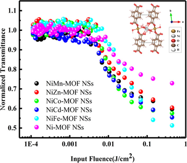
To further illustrate the difference between the optical limiting performance of the Ni-M-MOF NSs (M = Mn, Zn, Co, Cd, Fe) and the Ni-MOF NSs, the optical limiting diagram, as shown in Figure 7, is obtained by a nonlinear fitting equation.52 The optical limiting properties of materials are closely related to the Fth. According to previous literature reports, among the reported materials (GONSs (>3 J/cm2), GNSs (0.5 J/cm2), MWCNTs (1.4 J/cm2), VSe2 (0.9 J/cm2), MOS2 (11.16 J/cm2), WS2 (7.2 J/cm2), (CoMoO4)8/PMMA (1.31 J/cm2)) have good optical limiting performance.49,56,57 From the optical limiting curve trend of the six materials in Table 1, it can be clearly seen that the threshold of Ni-M-MOF NSs (M = Mn, Zn, Co, Cd, Fe) is Fe < Cd < Co < Mn ≈ Zn ≪ Ni, suggest that the optical limiting performance of the Ni-M-MOF NSs (M = Mn, Zn, Co, Cd, Fe) has been improved, which is consistent with the results of the Z-scan. Especially for the Ni-Fe-MOF NSs, the optical limiting threshold (0.43 J/cm2) is better than the GNSs (0.5 J/cm2). Together, all of these indicate that the mixed MOF NSs are potential materials with a significant application value.
Figure 7.
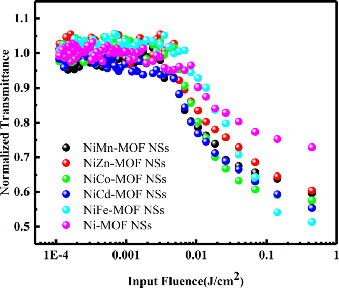
Optical limiting curve of Ni-MOF NSs and Ni-M-MOF NSs (M = Mn, Zn, Co, Cd, Fe) with input power (50 μJ) at 532 nm in ethanol.
4. Conclusions
To sum up, ultrathin MOF NSs are synthesized by the traditional solvothermal method. The third-order nonlinear optical responses of Ni-MOF NSs and Ni-M-MOF NSs (M = Mn, Zn, Co, Cd, Fe) are studied by the Z-scan method at 532 nm. The results show that these MOF NSs have strong reverse saturated absorption and a broad and very weak absorption (from 400 to 800 nm). Especially, Ni-Fe-MOF NSs have a better optical limiting threshold (Fth = 0.43 J/cm2) than the GNSs (Fth = 0.5 J/cm2). Therefore, ultrathin mixed MOF NSs materials play a great role in the protection of precision optical instruments, have a great application potential in nonlinear optics and photonics.
Acknowledgments
Project supported by the Natural Science Foundation of the Fujian Province, China (Grant Nos. 2020J01476, 2020J011087), Fuzhou Technology Innovation Fund Project for Small and Medium-sized Technological SMEs (Grant No. 2020-CX-165), Medical Innovation Project of Fujian Provincial Health Commission (Grant No. 2020CXA006), and Research startup Foundation of Fuzhou University (Grant No. GXRC-19017).
Glossary
Abbreviations
- MOF
Metal–Organic Frameworks
- RSA
Reverse Saturable Absorption
- NLO
Nonlinear Optical
- DMAC
N,N-Dimethylacetamide
- XRD
X-ray Diffraction
- FTIR
Fourier Transform Infrared Spectroscopy
- XPS
X-ray Photoelectron Spectroscopy
- UV
Ultraviolet
- SEM
Scanning Electron Microscope
- TEM
Transmission Electron Microscope
- AFM
Atomic Force Microscope
- HAADF-STEM
High-Angle Annular Dark-Field Scanning Transmission Electron Microscope
- EDX
Energy Dispersive X-ray
- GONSs
Graphene Oxide Nanosheets
- GNSs
Graphene Nanosheets
- MWCNTs
Multi-Walled Carbon Nanotubes
- NSs
Nanosheets
- GOZs
Graphene Oxide-ZnS
- PMMA
Poly(methyl methacrylate)
Supporting Information Available
The Supporting Information is available free of charge at https://pubs.acs.org/doi/10.1021/acsomega.1c07196.
The SEM and TEM image of Ni-M-MOF NSs (M = Cd, Mn, Zn, Co) and Ni-MOF NSs; thickness of Ni-Fe-MOF nanosheets; XPS pattern of Ni-Fe-MOF NSs; XRD pattern of Ni-M-MOF NSs (M = Cd, Mn, Zn, Co) and Ni-MOF NSs; IR spectrum of Ni-M-MOF NSs (M = Cd, Mn, Zn, Co); open-aperture Z-scan results of Ni-M-MOF NSs (M = Zn, Co) and Ni-MOF NSs (PDF)
The authors declare no competing financial interest.
Supplementary Material
References
- Jiang X.; Zhang L.; Liu S.; Zhang Y.; He Z.; Li W.; Zhang F.; Shi Y.; Lue W.; Li Y.; et al. Ultrathin Metal-Organic Framework: An Emerging Broadband Nonlinear Optical Material for Ultrafast Photonics. Adv. Opt. Mater. 2018, 6, 1800561. 10.1002/adom.201800561. [DOI] [Google Scholar]
- Shin S. M.; Lee M. S.; Han J. H.; Jeong N. Assessing the Guest-accessible Volume in MOFs Using Two-photon Fluorescence Microscopy. Chem. Commun. 2014, 50, 289–291. 10.1039/C3CC44008G. [DOI] [PubMed] [Google Scholar]
- Tan C.; Cao X.; Wu X.; He Q.; Yang J.; Zhang X.; Chen J.; Zhao W.; Han S.; Nam G.; et al. Recent Advances in Ultrathin Two-Dimensional Nanomaterials. Chem. Rev. 2017, 117, 6225–6331. 10.1021/acs.chemrev.6b00558. [DOI] [PubMed] [Google Scholar]
- Li J.; Sculley J.; Zhou H. Metal-Organic Frameworks for Separations. Chem. Rev. 2012, 112, 869–932. 10.1021/cr200190s. [DOI] [PubMed] [Google Scholar]
- Li D.; Gu Z.; Zhang J. Auto-controlled Fabrication of a Metal-porphyrin Framework Thin Film with Tunable Optical Limiting Effects. Chem. Sci. 2020, 11, 1935–1942. 10.1039/C9SC05881H. [DOI] [PMC free article] [PubMed] [Google Scholar]
- Medishetty R.; Zareba J. K.; Mayer D.; Samoc M.; Fischer R. A. Nonlinear Optical Properties, Upconversion and Lasing in Metal-Organic Frameworks. Chem. Soc. Rev. 2017, 46, 4976–5004. 10.1039/C7CS00162B. [DOI] [PubMed] [Google Scholar]
- Lustig W. P.; Mukherjee S.; Rudd N. D.; Desai A. V.; Li J.; Ghosh S. K. Metal-Organic Frameworks: Functional Luminescent and Photonic Materials for Sensing Applications. Chem. Soc. Rev. 2017, 46, 3242–3285. 10.1039/C6CS00930A. [DOI] [PubMed] [Google Scholar]
- Rocha J.; Carlos L. D.; Almeida Paz F. A.; Ananias D. Luminescent Multifunctional Lanthanides-Based Metal-Organic Frameworks. Chem. Soc. Rev. 2011, 40, 926–940. 10.1039/C0CS00130A. [DOI] [PubMed] [Google Scholar]
- Lustig W. P.; Mukherjee S.; Rudd N. D.; Desai A. V.; Li J.; Ghosh S. K. Metal-organic Frameworks: Functional Luminescent and Photonic Materials for Sensing Applications. Chem. Soc. Rev. 2017, 46, 3242–3285. 10.1039/C6CS00930A. [DOI] [PubMed] [Google Scholar]
- Guo B. 2D Noncarbon Materials-Based Nonlinear Optical Devices for Ultrafast Photonics. Chin. Opt. Lett. 2018, 16, 020004. 10.3788/COL201816.020004. [DOI] [Google Scholar]
- Yan J.; Liu T.; Liu X.; Yan Y.; Huang Y. Metal-organic Framework-based Materials for Flexible Supercapacitor Application. Coord. Chem. Rev. 2022, 452, 214300. 10.1016/j.ccr.2021.214300. [DOI] [Google Scholar]
- Zhou Y.; Abazari R.; Chen J.; Tahir M.; Kumar A.; Ikreedeegh R. R.; Rani E.; Singh H.; Kirillov A. M. Bimetallic Metal-organic Frameworks and MOF-Derived Composites: Recent Progress on Electro- and Photo Electrocatalytic Applications. Coord. Chem. Rev. 2022, 451, 214264. 10.1016/j.ccr.2021.214264. [DOI] [Google Scholar]
- Chuhadiya S.; Himanshu; Suthar D.; Patel S. L.; Dhaka M. S. Metal Organic Frameworks as Hybrid Porous Materials for Energy Storage and Conversion Devices: A review. Coord. Chem. Rev. 2021, 446, 214115. 10.1016/j.ccr.2021.214115. [DOI] [Google Scholar]
- Pei J. Y.; Wen H. M.; Gu X. W.; Qian Q. L.; Yang Y.; Cui Y. J.; Li B.; Chen B. L.; Qian G. D. Dense Packing of Acetylene in a Stable and Low-Cost Metal-Organic Framework for Efficient C2H2/CO2 Separation. Angew. Chem., Int. Ed. 2021, 60, 25068–25074. 10.1002/anie.202110820. [DOI] [PubMed] [Google Scholar]
- Zhang L.; Jiang K.; Yang L.; Li L.; Hu E.; Yang L.; Shao K.; Xing H.; Cui Y.; Yang Y.; Li B.; Chen B.; Qian G. Benchmark C2H2/CO2 Separation in an Ultra-Microporous Metal-Organic Framework via Copper(I)-Alkynyl Chemistry. Angew. Chem., Int. Ed. 2021, 60, 15995–16002. 10.1002/anie.202102810. [DOI] [PubMed] [Google Scholar]
- Li D.; Xu H.; Jiao L.; Jiang H. Metal-Organic Frameworks for Catalysis: State of the Art, Challenges, and Opportunities. Energy. Chem. 2019, 1, 100005. 10.1016/j.enchem.2019.100005. [DOI] [Google Scholar]
- Jiao Y.; Pei J.; Chen D.; Yan C.; Hu Y.; Zhang Q.; Chen G. Mixed-Metallic MOF Based Electrode Materials for High Performance Hybrid Supercapacitors. J. Mater. Chem. A 2017, 5, 1094–102. 10.1039/C6TA09805C. [DOI] [Google Scholar]
- Yu J.; Cui Y.; Wu C.; Yang Y.; Chen B.; Qian G. Two-Photon Responsive Metal Organic Framework. J. Am. Chem. Soc. 2015, 137, 4026–9. 10.1021/ja512552g. [DOI] [PubMed] [Google Scholar]
- Liang J.; Liang Z.; Zou R.; Zhao Y. Heterogeneous Catalysis in Zeolites, Mesoporous Silica, and Metal-Organic Frameworks. Adv. Mater. 2017, 29, 1701139. 10.1002/adma.201701139. [DOI] [PubMed] [Google Scholar]
- Medishetty R.; Nalla V.; Nemec L.; Henke S.; Mayer D.; Sun H.; Reuter K.; Fischer R. A. A New Class of Lasing Materials: Intrinsic Stimulated Emission from Nonlinear Optically Active Metal-Organic Frameworks. Adv. Mater. 2017, 29, 1605637. 10.1002/adma.201605637. [DOI] [PubMed] [Google Scholar]
- Zheng H. Q.; Liu C. Y.; Zeng X. Y.; Chen J.; Lü J.; Lin R. G.; Cao R.; Lin Z. J.; Su J. W. MOF-808: A Metal-Organic Framework with Intrinsic PeroxidaseLike Catalytic Activity at Neutral pH for Colorimetric Biosensing. Inorg. Chem. 2018, 57, 9096–9104. 10.1021/acs.inorgchem.8b01097. [DOI] [PubMed] [Google Scholar]
- Zhu Y.; Kang Y.; Gu Z.; Zhang J. Step by Step Bisacrificial Templates Growth of Bimetallic Sulfide QDs-Attached MOF Nanosheets for Nonlinear Optical Limiting. Adv. Opt. Mater. 2021, 9, 2002072. 10.1002/adom.202002072. [DOI] [Google Scholar]
- Zhang H. Ultrathin Two-Dimensional Nanomaterials. ACS Nano 2015, 9, 9451–9469. 10.1021/acsnano.5b05040. [DOI] [PubMed] [Google Scholar]
- Lei T.; Lu W.; Lu W.; Cui B.; Hu R.; Shi W.; Zeng Z. Photogating Effect in Two-dimensional Photodetectors. Acta Phys. Sin. Chin. Ed. 2021, 70, 027801. 10.7498/aps.70.20201325. [DOI] [Google Scholar]
- Shi N.; Song C.; Zhang J.; Huang W. Preparation and Optoelectronic Applications of Two-Dimensional Nanocrystals Based on Metallo-Porphyrins. Acta Phys. Chin. Sin. 2016, 32, 2447–2461. 10.3866/PKU.WHXB201607141. [DOI] [Google Scholar]
- Zheng J.; Miao T.; Xu R.; Ping X.; Wu Y.; Lu Z.; Zhang Z.; Hu D.; Liu L.; Zhang Q.; et al. Chemical Synthesis and Integration of Highly Conductive PdTe2 with Low-Dimensional Semiconductors for p-Type Transistors with Low Contact Barriers. Adv. Mater. 2021, 33, 2101150. 10.1002/adma.202101150. [DOI] [PubMed] [Google Scholar]
- Rui K.; Zhao G.; Chen Y.; Lin Y.; Zhou Q.; Chen J.; Zhu J.; Sun W.; Huang W.; Dou S. X. Hybrid 2D Dual-Metal-Organic Frameworks for Enhanced Water Oxidation Catalysis. Adv. Fun. Mater. 2018, 28, 1801554. 10.1002/adfm.201801554. [DOI] [Google Scholar]
- Abazari R.; Yazdani E.; Nadafan M.; Kirillov A. M.; Gao J.; Slawin A. M. Z.; Carpenter-Warren C. L. Third-Order Nonlinear Optical Behavior of an Amide-Tricarboxylate Zinc (II) Metal-Organic Framework with Two-Fold 3D+3D Interpenetration. In. Chem. 2021, 60, 9700–9708. 10.1021/acs.inorgchem.1c00997. [DOI] [PubMed] [Google Scholar]
- Zhang X.; Li L.; Wang J. X.; Wen H. M.; Krishna R.; Wu H.; Zhou W.; Chen Z. N.; Li B.; Qian G.; Chen B. Selective Ethane/Ethylene Separation in a Robust Microporous Hydrogen-Bonded Organic Framework. J. Am. Chem. Soc. 2020, 142, 633–640. 10.1021/jacs.9b12428. [DOI] [PMC free article] [PubMed] [Google Scholar]
- Pei J.; Shao K.; Wang J.; Wen H.; Yang Y.; Cui Y.; Krishna R.; Li B.; Qian G. A Chemically Stable Hofmann-Type Metal-Organic Framework with Sandwich-Like Binding Sites for Benchmark Acetylene Capture. Adv. Mater. 2020, 32, 1908275. 10.1002/adma.201908275. [DOI] [PubMed] [Google Scholar]
- Zheng J.; Du H.; Jiang F.; Zhang Z.; Sa B.; He W.; Jiao L.; Zhan H. Rapid and Large-Scale Quality Assessment of Two-Dimensional MoS2 Using Sulfur Particles with Optical Visualization. Nano Lett. 2021, 21, 1260–1266. 10.1021/acs.nanolett.0c03884. [DOI] [PubMed] [Google Scholar]
- Burch K. S.; Mandrus D.; Park J. Magnetism in Two-Dimensional Van Der Waals Materials. Nature 2018, 563, 47–52. 10.1038/s41586-018-0631-z. [DOI] [PubMed] [Google Scholar]
- Yaghi O. M.; O’Keeffe M.; Ockwig N. W.; Chae H. K.; Eddaoudi M.; Kim J. Reticular Synthesis and the Design of New Materials. Nature 2003, 423, 705–714. 10.1038/nature01650. [DOI] [PubMed] [Google Scholar]
- Tang C. S.; Zhang H.; Cheung C. Y. Y.; Xu M.; Ho J. C. Y.; Zhou W.; Cherny S. S.; Zhang Y.; Holmen O.; Au K.; et al. Exome-wide Association Analysis Reveals Novel Coding Sequence Variants Associated with Lipid Traits in Chinese. Nat. Commun. 2015, 6, 10206. 10.1038/ncomms10206. [DOI] [PMC free article] [PubMed] [Google Scholar]
- Yu J.; Cui Y.; Xu H.; Yang Y.; Wang Z.; Chen B.; Qian G. Confinement of Pyridinium Hemicyanine Dye Within an Anionic Metal-Organic Framework for Two-Photon-Pumped Lasing. Nat. Commun. 2013, 4, 2719. 10.1038/ncomms3719. [DOI] [PMC free article] [PubMed] [Google Scholar]
- Low T.; Chaves A.; Caldwell J. D.; Kumar A.; Fang N. X.; Avouris P.; Heinz T. F.; Guinea F.; Martin-Moreno L.; Koppens F. Polaritons in Layered Two-dimensional Materials. Nat. Mater. 2017, 16, 182–194. 10.1038/nmat4792. [DOI] [PubMed] [Google Scholar]
- Xia F.; Wang H.; Xiao D.; Dubey M.; Ramasubramaniam A. Two-dimensional Material Nanophotonics. Nat. Photonics 2014, 8, 899–907. 10.1038/nphoton.2014.271. [DOI] [Google Scholar]
- Bonaccorso F.; Sun Z. Solution Processing of Graphene, Topological Insulators and other 2D Crystals for Ultrafast Photonics. Opt. Mater. Express 2014, 4, 63–78. 10.1364/OME.4.000063. [DOI] [Google Scholar]
- Zhang C.; Liu J.; Gao Y.; Li X.; Lu H.; Wang Y.; Feng J.; Lu J.; Ma K.; Chen X. Porous Nickel Oxide Micron Polyhedral Particles for High-performance Ultrafast Photonics. Opt. Laser Technol. 2022, 146, 107546. 10.1016/j.optlastec.2021.107546. [DOI] [Google Scholar]
- Tang S.; He Z.; Liang G.; Chen S.; Ge Y.; Sang D. K.; Lu J.; Lu S.; Wen Q.; Zhang H. Pulse Duration Dependent Nonlinear Optical Response in Black Phosphorus Dispersions. Opt. Commun. 2018, 406, 244–248. 10.1016/j.optcom.2016.11.036. [DOI] [Google Scholar]
- Haus J. W.; Mozumder Z.; Zhan Q. Azimuthal Modulation Instability for a Cylindrically Polarized Wave in a Nonlinear Kerr Medium. Opt. Express 2006, 14, 4757–4764. 10.1364/OE.14.004757. [DOI] [PubMed] [Google Scholar]
- Karampitsos N.; Kyrginas D.; Couris S. On the Measurement of the Nonlinear Optical Response of Graphene Dispersions Using Fs Lasers. Opt. Lett. 2020, 45, 1814–1817. 10.1364/OL.389309. [DOI] [PubMed] [Google Scholar]
- Nicolosi V.; Chhowalla M.; Kanatzidis M. G.; Strano M. S.; Coleman J. N. Liquid Exfoliation of Layered Materials. Science 2013, 340, 1420. 10.1126/science.1226419. [DOI] [Google Scholar]
- Li F.; Wang P.; Huang X.; Young D. J.; Wang H.; Braunstein P.; Lang J. Large-Scale, Bottom-Up Synthesis of Binary Metal-Organic Framework Nanosheets for Efficient Water Oxidation. Ange. Chem. Int. Ed. 2019, 58, 7051–7056. 10.1002/anie.201902588. [DOI] [PubMed] [Google Scholar]
- Perdew J. P.; Burke K.; Ernzerhof M. Generalized Gradient Approximation Made Simple. Phys. Rev. Lett. 1996, 77, 3865–3868. 10.1103/PhysRevLett.77.3865. [DOI] [PubMed] [Google Scholar]
- Giannozzi P.; Baroni S.; Bonini N.; Calandra M.; Car R.; Cavazzoni C.; Ceresoli D.; Chiarotti G. L.; Cococcioni M.; Dabo I. QUANTUM ESPRESSO: a Modular and Open-Source Software Project for Quantum Simulations of Materials. J. Phys.: Condens. Matter. 2009, 21, 395502. [DOI] [PubMed] [Google Scholar]
- Dal Corso A. Pseudopotentials Periodic Table: From H to Pu. Comput. Mater. Sci. 2014, 95, 337. 10.1016/j.commatsci.2014.07.043. [DOI] [Google Scholar]
- Giannozzi P.; Andreussi O.; Brumme T.; Bunau O.; Buongiorno Nardelli M.; Calandra M.; Car R.; Cavazzoni C.; Ceresoli D.; Cococcioni M.; et al. Advanced Capabilities for Materials Modelling with Quantum ESPRESSO. J. Phys.: Condens. Matter. 2017, 29, 465901. 10.1088/1361-648X/aa8f79. [DOI] [PubMed] [Google Scholar]
- Feng M.; Zhan H. B.; Chen Y. Nonlinear Optical and Optical Limiting Properties of Graphene Families. Appl. Phys. Lett. 2010, 96, 033107. 10.1063/1.3279148. [DOI] [Google Scholar]
- Ye J.; Zhou X.; Wang Y.; Huang R.; Zhou H.; Cheng X.; Ma Y.; Zhang J. Room-Temperature Sintered Metal-Organic Framework Nanocrystals: A New Type of Optical Ceramics. Sci. Chin. Mater. 2018, 61, 424–428. 10.1007/s40843-017-9184-1. [DOI] [Google Scholar]
- Ye C.; Yang Z.; Dong J.; Huang Y.; Song M.; Sa B.; Zheng J.; Zhan H. Layer-Tunable Nonlinear Optical Characteristics and Photocarrier Dynamics of 2D PdSe2 in Broadband Spectra. Small 2021, 17, 2103938. 10.1002/smll.202103938. [DOI] [PubMed] [Google Scholar]
- Sheikbahae M.; Said A. A.; Wei T. H.; et al. Sensitive Measurement of Optical Nonlinearities Using a Single Beam. IEEE J. QE 1990, 26, 760–769. 10.1109/3.53394. [DOI] [Google Scholar]
- Ouyang Q.; Yu H.; Zhang K.; Chen Y. Saturable Absorption and the Changeover from Saturable Absorption to Reverse Saturable Absorption of MoS2 Nanoflake Array Films. J. Mater. Chem. C 2014, 2, 6319–6325. 10.1039/C4TC00909F. [DOI] [Google Scholar]
- Chen Y.; Hanack M.; Araki Y.; Ito O. Axially modified gallium phthalocyanines and naphthalocyanines for optical limiting. Chem. Soc. Rev. 2005, 34, 517–529. 10.1039/b416368k. [DOI] [PubMed] [Google Scholar]
- Zhou G. J.; Wong W. Y.; Ye C.; Lin Z. Optical Power Limiters Based on Colorless Di-, Oligo-, and Polymetallaynes: Highly Transparent Materials for Eye Protection Devices. Adv. Funct. Mater. 2007, 17, 963–975. 10.1002/adfm.200600855. [DOI] [Google Scholar]
- Liang C.; Wang E.; Li X.; Wang J.; Liu Y.; Chen B.; Chen H.; Liu Y.; Peng X. Optical Limiting Performances of Transitional Metal Dichalcogenides MX2 (M = V, Nb, Ta; X = S, Se) with Ultralow Initial Threshold and Optical Limiting Threshold. Chin. Opt. Lett. 2022, 20, 021901. 10.3788/COL202220.021901. [DOI] [Google Scholar]
- Dong N.; Li Y.; Feng Y.; Zhang S.; Zhang X.; Chang C.; Fan J.; Zhang L.; Wang J. Optical Limiting and Theoretical Modelling of Layered Transition Metal Dichalcogenide Nanosheets. Sci. Rep. 2015, 5, 14646. 10.1038/srep14646. [DOI] [PMC free article] [PubMed] [Google Scholar]
- Wang P.; Wang Y.; Yuan C.; Chen B.; Zhang T.; Li B.; Ouyang Q. Nonlinear absorption, refraction and optical limiting properties of cobalt molybdate microcrystals. Opt. Mater. 2022, 124, 111972. 10.1016/j.optmat.2022.111972. [DOI] [Google Scholar]
Associated Data
This section collects any data citations, data availability statements, or supplementary materials included in this article.