Abstract
Vitreous cortex hyalocytes are resident macrophage cells that help maintain the transparency of the media, provide immunosurveillance, and respond to tissue injury and inflammation. In this study, we demonstrate the use of non-confocal quadrant-detection adaptive optics scanning light ophthalmoscopy (AOSLO) to non-invasively visualize the movement and morphological changes of the hyalocyte cell bodies and processes over 1-2 hour periods in the living human eye. The average velocity of the cells 0.52 ± 0.76 µm/min when sampled every 5 minutes and 0.23 ± 0.29 µm/min when sampled every 30 minutes, suggesting that the hyalocytes move in quick bursts. Understanding the behavior of these cells under normal physiological conditions may lead to their use as biomarkers or suitable targets for therapy in eye diseases such as diabetic retinopathy, preretinal fibrosis and glaucoma.
1. Introduction
The term “hyalocytes” was introduced in 1960s by Balazs to describe a homogeneous population of cells in the cortical layer of the ocular vitreous body of various animal species [1]. Under physiological conditions, these cells are primarily located both anteriorly, adjacent to the ciliary epithelium, and posteriorly, above the vitreoretinal interface. Vitreous cortex hyalocytes, are considered the resident macrophages within the formed vitreous [2,3], have been reported to localize at an average distance of 50 µm from the inner limiting membrane (ILM), often entangled with collagen fibrils that compose the vitreous cortex [4,5]. In their “resting state,” hyalocytes play a significant role in the maintenance of the vitreous body as a transparent and avascular system, clearing debris from the vitreous and secreting anti-angiogenic factors that inhibit the growth of vessels within it [6,7]. Hyalocytes have also been found to play pivotal roles inhibiting intraocular inflammation, changing their morphology, immunophenotype and density in response to damage or external threats [2,8]. It has been speculated that dysregulation due to mechanically-induced schisis of the vitreous cortex in the presence of inflammation may activate the hyalocytes stimulating them to transmorph into fibrocyte-like state and recruit other cell types contributing to the formation of epiretinal membranes [9,10]. Their migration towards vessels in advancing diabetic retinopathy would also suggest an attraction to exuded VEGF and their involvement in the transition to neovascular diabetic retinopathy [11,12]. Their presence at the anterior vitreous would also suggest their involvement in proliferative vitreoretinopathy [13,14]. The ability to control these cells may therefore be an important therapeutic target for intraocular diseases.
Prior in vivo adaptive optics imaging, resident macrophages such as vitreous cortex hyalocytes and microglia, were identified using exogenous or transgenic fluorescent labeling in animal models [15–18]. Recent technical advances have enabled the direct, label-free visualization of these cells in humans using adaptive optics optical coherence tomography (AO-OCT) [19–22]. While the visualization of hyalocyte cells bodies and processes with this technique is exceptional, detailed characterization of their morphological changes and displacement has been limited by the transverse resolution and signal-to-noise ratio (SNR) in fluorescence, or speckle in AO-OCT.
Adaptive optics scanning light ophthalmoscopy (AOSLO) is a non-invasive point-scanning imaging technique capable of video-rate visualization of tissues at cellular and sub-cellular scales. In this technique, the retina is illuminated with a focused spot that is re-imaged onto one or more light detectors after being scattered by the sample. The wavefront aberrations of the optics of the eye and the instrument itself are mitigated by a wavefront corrector, typically a deformable mirror, providing near diffraction-limited retinal imaging. AOSLO imaging has revealed a variety of previously unseen retinal structures and pathology [23–30].
The backscattered light in any point-scanning ophthalmoscope can be separated into confocal and non-confocal components. The confocal component consists of singly scattered light which has been isolated from the non-confocal component using spatial filtering with a pinhole, sized in accordance with retinal structure of interest [31]. The non-confocal component, consisting of multiply scattered photons [25,32], has been captured using a variety of detection schemes such as an offset detector [25,33], split-detection by dividing an annular detection area into two halves [34] or quadrant-detection by dividing it into four sections [31], or more [35]. When using either a single offset aperture or split-detection, however, the image contrast is limited to a preferred direction. Using these imaging strategies, the edges of structures such as spindle-shaped hyalocytes and blood vessels whose long axes run parallel to the detector direction, are obscured by limited contrast [36]. As a result, the ability to resolve and characterize transparent structures using multiply scattered light is highly dependent on the directional orientation of non-confocal aperture and how it relates to the geometry and orientation of the retinal structure being imaged. Prior studies have overcome this orientation-dependence by capturing images using multi-offset detection pattern [33,37,38] or quadrant-detectors oriented at orthogonal directions [31]. Several recent studies have explored the mechanism of contrast of non-confocal imaging, and shown that illumination beam refraction from the edges of cells and vessels leads to preferential detection on offset detectors [37–39], and enhanced the contrast in post-processing to visualize retinal ganglion cells [37,38], and macrophage cells on the retinal surface [38].
In this study, we address this orientation-dependence by capturing images using a quadrant-detection AOSLO [31], and merging the non-confocal images after utilizing a directional difference filtering approach. Using this approach, we were able to reliably image hyalocytes above the vitreoretinal interface in the living human retina, regardless of cell feature orientation. Finally, as a first attempt at developing a hyalocyte activity biomarker for future clinical studies, we measured hyalocyte body movements.
2. Methods
2.1. Subjects
This study was performed at the New York Eye and Ear Infirmary of Mount Sinai. All procedures adhered to the tenets of the Declaration of Helsinki and were approved by the Institutional Review Board of Mount Sinai Hospital (identifier: 20-03937). Written informed consent was obtained from all subjects after an explanation of possible risks. A total of 8 subjects were recruited who had no known retinal pathology (age mean ± SD: 28.6 ± 3.7 years; range: 24-35 years; 6 males, 2 females). Inclusion criteria required having a natural crystalline lens and clear ocular media, and capable of pupil dilation to at least 5 mm. Subjects were excluded if they had been previously diagnosed with systemic medical conditions such as diabetes. To be eligible for imaging, each subject had to have at least one eye which had not had previous eye surgery, retinal pathology, or difficulty fixating on a target. Only one eye from each subject was imaged. Prior to imaging, one drop of 2.5% phenylephrine and one drop of 1% tropicamide were instilled to achieve dilation of the pupil and cycloplegia. During imaging, some subjects required a second drop of 1% tropicamide if dilation or cycloplegia began to wear off.
2.2. AOSLO and clinical OCT instruments
The quadrant-detection AOSLO instrument used in this study is a custom device which has been previously described [31,40]. Instrument settings and acquisition parameters are shown in Table 1.
Table 1. Parameters of quadrant-detection adaptive optics scanning light ophthalmoscope system.
| System Parameters | Value |
|---|---|
| Imaging Wavelength and Peak Power a | 790 nm, 150 µW |
| Beacon Wavelength and Peak Power a | 830 nm, 20 µW |
| Beam Size at Pupil of the Eye | 7.75 mm |
| Confocal Detection Pinhole Size | 1 Airy Disk |
| Non-Confocal Annulus Outer Diameter | 20 Airy Disks |
| Non-Confocal Annulus Inner Diameter | 2 Airy Disks |
| Field of View | ∼1×1° |
| Horizontal Scanning Rate | 15 kHz |
| Horizontal/Vertical Number of Pixels | 768/650 |
| Digitizer Pixel Clock | 40 MHz |
| Frame Rate | 16.6 fps |
The continuous wave light source (CW) was turned ON only in the portions of the scanner raster necessary for imaging, and off elsewhere. Therefore, average power was approximately 2.5 times lower than peak power.
The AOSLO simultaneously collected confocal and non-confocal quadrant-detection images using a circular pinhole ∼1 Airy disk in diameter and an annular mask 2-20 Airy disk in diameter, respectively. The confocal and non-confocal light were separated by using a tilted reflective mask which transmitted the confocal light [31]. The non-confocal light, after passing through an annular aperture, is divided into 4 equal quadrants via a series of lens relays and mirrors before reaching the sensitive area of photomultiplier tubes (H7422-50-A, Hamamatsu Photonics, Hamamatsu, Japan) [34,41]. During imaging, the pupil of the eye was aligned to overlap with that of the AOSLO using a bite bar mounted on a manually-operated three-axis translation stage.
Optical coherence tomography (OCT) imaging was performed using a commercial instrument capturing 70,000 A-scans per second, using a light source with a 45 nm bandwidth centered around 840nm (Avanti RTVue-XR; Optovue Inc., Fremont, CA, USA). The axial and lateral resolutions of the device are 5 and 15 µm, respectively. OCT volumes were captured in angiographic mode, which renders both retinal perfusion (OCT-A) and structural (OCT-R) data. A total of 608 B-scans, each composed of 304 A-scans, are acquired per volume, with two sequential B-scans captured at each location to generate the perfusion maps. A second volume is then obtained immediately afterward to facilitate removal of eye movement distortion through image registration, using a fast-scanning B-scan orientation orthogonal to the first volume. These data compose the final volume, which consists of a motion-corrected amalgam of the two volume scans [42] with 304 by 304 pixels along the x and y axis, and 640 pixels along the z (depth) axis.
2.3. AOSLO and clinical OCT Imaging sessions
To study the hyalocyte movement we performed AOSLO and OCT imaging at multiple time points targeting retinal locations approximately 3 mm temporal to the fovea, where hyalocytes are known to localize at high density in the normal retina [11,22].
Imaging sessions followed either a 2-hour or 1-hour protocol. In the 2-hour sessions, 3 or more regions of interest (ROIs) were imaged every 30 minutes, capturing at least 2 image sequences (each with 300 frames, ∼18 s duration). More than 2 sequences were often taken if the ROI did not overlap well with the images obtained at prior time points or if the subject struggled with eye fixation or blinking. Obtaining multiple image sequences increased the chances that at least one was of sufficient quality for visualizing the hyalocyte cells clearly. Only one of these image sequences, chosen for its focus and contrast, was used for hyalocytes movement analysis. Subject realignment and image capture introduced some variability in the interval between sequences, but they were always less than 10 minutes. Following the first AOSLO imaging session, ten 3×3mm OCT scans were captured over the same temporal region imaged with the AOSLO. This OCT imaging was repeated within 15 minutes after the last AOSLO imaging time point. All 8 subjects underwent the 2-hour imaging protocol.
In the 1-hour sessions a similar protocol was employed with the exception that, a single ROI at the temporal retina was imaged with AOSLO every 5 minutes for a total of 13 time points. Ten 3 × 3mm OCT scans covering the same ROI was performed within 15 minutes prior the beginning of the 1-hour session and no more than 15 minutes following the last AOSLO image taken. Three of the 8 subjects underwent the 1-hour imaging protocol.
At the conclusion of each subject’s imaging session, the axial length of the studied eye was measured using an ocular biometer (IOL Master, Carl Zeiss Meditech, Inc., Dublin, CA, USA), to estimate the retinal magnification factor as previously described [34].
2.4. AOSLO image processing and analysis
To enhance the visualization of the hyalocytes and graph their movement over time, image registration and averaging was performed on all acquired images.
2.4.1. AOSLO image sequence registration and averaging of single time point
The AOSLO image sequences consisted of five simultaneously sampled imaging channels (1 confocal and 4 non-confocal). Images from all five channels were equally affected by eye movement, tear film stability, and blinking. Motion artifacts were removed using a semi-automated software, which divided each image in the sequence into narrow horizontal strips and registered them to a template, which was manually chosen as the least distorted frame of the sequence [43]. Once the image sequences were registered against the template and the ones with highest normalized cross-correlation were averaged to create high SNR images. The channel with the best subjective image contrast, typically the confocal channel, was selected for implementing motion correction. The same motion correction was then applied to all five channels. Stabilized image sequences, consisting of 100 to 200 frames, were used to generate a single averaged image for each channel.
2.4.2. Registering averaged AOSLO images from multiple time points
The averaged confocal images from each ROI were then registered across the time points using the Register Virtual Stack Slices plugin on ImageJ (ImageJ, US National Institutes of Health, Bethesda MD, USA) [44]. The registration model employed was either the elastic [45] or the similarity. All images were first registered using the elastic model via bUnwarpJ. If successful registration was not achieved due to inadequate image contrast, the similarity model was then performed. The transformation matrix computed on each of these registration steps was applied to the remaining 4 non-confocal images using Transform Virtual Stack Slices plugin so that all AOSLO channels were co-registered. After registration of the images captured at different time points, these images were cropped to their minimum overlapping rectangular area. In the 2-hour datasets, due to some motion distortions remaining after the first registration, this registration process was repeated.
2.4.3. Split-detection image calculation
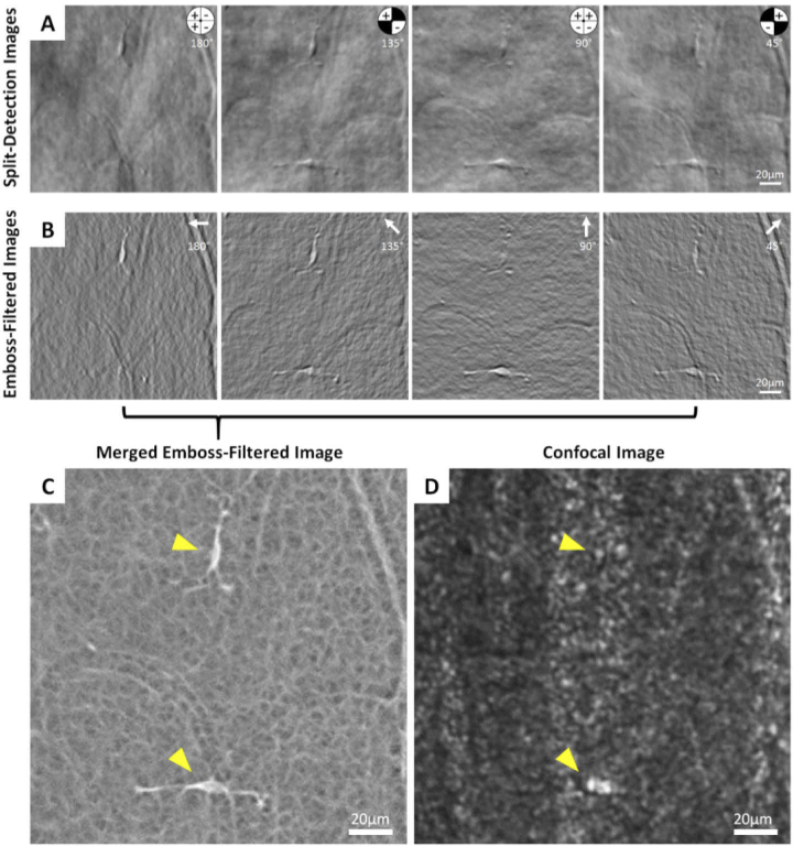
The intensity of the 4 non-confocal averaged images were normalized at each time point and used to calculate horizontal, vertical and diagonal split-detection images by either subtracting or adding quadrant images and dividing by their sum as described by Sredar et al. [31]. The resulting split-detection images (see example in Fig. 1(A)), appear as a mostly gray background with tissue features of cells or blood vessels resembling surface reliefs which are illuminated from one direction. We define the split-detection direction as being the angle from which the illumination appears to have originated, relative to a positive horizontal x-axis (pointing to the left) [31]. In Fig. 1(A), an inset of the non-confocal aperture indicates which quadrant was added, subtracted, or excluded to generate the 4 desired split directions (180, 135, 90 and 45°). The cell in the upper part of the image is elongated in the vertical direction, with the cell body and processes highest contrast in the horizontal split direction (180°) and lowest in the vertical split direction (90°). The opposite is true for the cell at the lower portion of the image, illustrating that no single split direction can provide optimal contrast for all cells, and hence the need for more than one split detection direction.
Fig. 1.
Image sequence illustrating the emboss filtering and merging of the four non-confocal quadrant-detection AOSLO images. (A) First, the split-detection images are computed by combining the non-confocal images as shown in the inset to create 4 separate split directions. The plus and minus signs in the quadrants on the top right corner of the image indicate which image was added and which one subtracted in the numerator of the split detection calculation [31]. (B) Next, each split-detection image is processed with an emboss filter, in which the filter direction (white arrows) matches the split direction. (C) The 4 emboss-filtered images were then merged into a single image using maximum intensity projection, which provides high contrast visualization of both hyalocytes and their processes in the same image (arrowheads) and reveals the complex meshwork structure of the surrounding. (D) The corresponding confocal image with locations of the same hyalocytes indicated.
2.4.4. Merging split-detection images after using a directional difference filtering approach
The split-detection images were further processed using the emboss (edge-enhancing) filter in the image editing software Photoshop 2021 (Adobe Systems, San Jose, CA). The filter parameters were set to a height of 3 pixels with the angle parameter matching the split direction of the selected image (Fig. 1(B)). The embossing algorithm replaces each pixel value with the difference between the adjacent pixels along the direction of interest. That is, for image with a split-detection along the horizontal image axis, the pixel values , where i and j are the row and column indices, are replaced with the value . This can be thought of as the average of the derivative of the split-detection to the left and right of each pixel. Given that the split-detection images themselves resemble differential phase imaging (as for example, Nomarski differential interference contrast), we can think of the embossed split-detection image as representing the curvature (i.e., second derivative) of the phase of the object being imaged. Therefore, if we think of the object being imaged as a phase object, that is an object that deflects but not attenuates the light passing through it, by computing the embossed images of the split-detection images for all four directions and then taking the maximum pixel value of each pixel, we are estimating the maximum curvature of the phase of the object of interest. Here is important to note that the maximum and minimum curvature images are substantially different, and given our split-detection sign convention, we chose the maximum because it provides the sharpest hyalocytes edges and highest contrast relative to the surrounding features.
The resulting images allow visualization of the cells and the portion of their processes proximal to the cell body irrespective of their orientation. Also visualized in the merged emboss-filtered image is a fine mesh across the entire field of view (Fig. 1(C); also see Supplementary Fig. S1 for a comparison of merged emboss-filtered images processed using Photoshop and MATLAB; Supplementary Fig. S2 for emboss filtering of split-detection images using MATLAB). This mesh is not visible in the corresponding confocal image, which shows the nerve fiber layer and occasionally a hint of hyalocyte body or process (Fig. 1(D)).
After merging of the 4 emboss-filtered images (Fig. 1(C)), the apparent cell size appears smaller than those in the split detection images (Fig. 1(A); Supplementary Fig. S3). Although the cell body and processes are visualized very clearly on the merged emboss-filtered images, it is not certain what constitutes the cell body or the processes extending from them. Due to these ambiguities, the cell body area and process movement were not quantitatively characterized.
2.4.5. Tracking cell body movement across time points
In the merged emboss-filtered images, the location of each cell was tracked across time using the TrackMate plugin in ImageJ in a semi-automated fashion with guidance from a grader [46]. The TrackMate settings were set to “Laplacian of Gaussian” detector with an estimated blob diameter of 30 pixels, which in our images corresponded to ∼15 µm. For each cell, the grader previewed its path through the time sequence and defined a limited region for tracking. The software tracked every point that it considered a potential cell, and the grader manually removed incorrectly tracked points. Cells whose bodies did not appear completely within the ROI for the entire time sequence were excluded from movement analysis. Cells were also excluded if they appeared to cross paths to eliminate any confusion as to particular cell’s identity.
The movement data was converted to distances using the retinal scaling factor derived from the ocular axial length [34]. The distance traveled between image sequences were divided by the time elapsed between them to calculate cell velocity. The final displacements were computed as the distance between the first and last position of the cells across the full session. The cumulative path length traveled by each cell was computed by summing the distance traveled between time points across the imaging period.
2.5. Clinical OCT image processing
OCT scans of hyalocyte distribution were obtained to confirm the optimal locations for ROIs chosen for AOSLO imaging. Image registration and averaging was performed on the OCT-R and OCT-A data to improve the SNR and visualization of retinal vessels and the hyalocytes above the ILM surface, as described in previous studies [11,47]. In brief, data from each OCT scan, including layer segmentation data were converted into a raw format using the Optovue XR-Avanti Exporting Tool software (version 2019.1.28). A custom MATLAB script was then used to generate a stack of 3 µm thick en face slabs of the OCT-R and OCT-A data that conformed to the shape of a selected retinal layer (MATLAB 2019; MathWorks, Natick, MA, USA). A 3 µm-thick OCT-A slab located at 40 µm below the ILM surface was selected from the each of the 10 individual volumes as a high-contrast image of blood vessels. These selected OCT-A slabs were registered together using the Register Virtual Stack Slices plugin on ImageJ [44]. The registration method was set to elastic [45]. The transformation matrices of these OCT-A registrations were then applied to all the OCT-R and OCT-A slabs which were then averaged together, generating a pair of high-contrast OCT-R and OCT-A scans. For the visualization of hyalocytes, three individual 3 µm OCT-R slabs were selected from the averaged scan, which were between the ILM layer and 9 µm above it in 3 µm increments. The slab which captured the most hyalocytes present within the ROI and the least visualization of the underlying nerve fiber layer was selected for further analysis.
The selected OCT-R and OCT-A images were then registered to the AOSLO images through multiple steps. First, an angiographic image was generated for each AOSLO region imaged using the standard deviation of the registered video of the AOSLO acquisition [48]. This AOSLO angiographic image served as a reference to which the OCT-A data was manually registered, using Photoshop. Using the registered OCT and AOSLO images, the correspondence between the hyalocyte locations at the beginning and end of each session was assessed and compared between modalities.
3. Results
3.1. Hyalocyte visualization within merged emboss-filtered AOSLO images
The AOSLO merged emboss-filtered images reveal the transparent hyalocyte cell bodies and their fine processes with diverse orientations against a complex mesh background, despite their poor visualization in the confocal images (Figs. 1(C) & 1D).
3.2. Comparing hyalocyte visualization on AOSLO and clinical OCT images
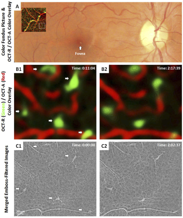
One of the goals of this study was to explore the microscopic features of cells previously described in clinical OCT images using AOSLO and to confirm that the cells are the same despite the differences in appearance due to the imaging modalities [11,12]. Images captured at ∼9° temporal to the fovea can be seen in Fig. 2 as an OCT-R/OCT-A color overlay superimposed on a color fundus photo, which is then compared to matching AOSLO images. OCT-R/OCT-A color overlay was generated using Photoshop as described previously [11]. In brief, the OCT-R hyalocyte layer was first coded in green and the OCT-A retinal vascular layer was coded in red. These two layers were then merged into a color overlay after contrast stretching. Between the first and last time points of the OCT-R/OCT-A color overlay images (Fig. 2(B)), the hyalocytes appeared at the same location with some subtle changes in shape and orientation of the cell body that coarsely match those seen in the corresponding AOSLO merged emboss-filtered images (Fig. 2(C)). These small differences between images are expected, given the ∼15 minutes between their capture, and can be observed in all subjects and retinal locations. The changes in cell body shape and processes, however, vary noticeably, and with exquisite detail in the AOSLO images. In the OCT images, on the other hand, the hyalocyte bodies appear substantially larger, likely due to the lower lateral resolution and averaging of the cell movements over ∼5-10 minutes required to capture the 10 OCT images that are needed to generate the averaged OCT images shown here.
Fig. 2.
Comparison of hyalocytes imaged using AOSLO and clinical OCT in a 31 year-old male. (A) 1.5 × 1.5 mm OCT-R/OCT-A color-overlay superimposed on the corresponding region of the color fundus photo. White box indicates a 1 × 1° ROI imaged using AOSLO. (B1-2) Magnified OCT-R/OCT-A color overlays of the white box in (A) taken approximately 2 hours apart. The color overlays show hyalocytes in green and capillaries in red, respectively. Five hyalocytes with relatively stationary position over 2 hours were observed (white arrows). (C1-2) Corresponding AOSLO merged emboss-filtered images also revealed the same hyalocytes over 2 hours with their cell body and processes varying noticeably in shape and orientation. Hyalocyte locations appear to match between imaging modalities, but the cell size and shape were different. Time of acquisition in the upper-right corner denotes the hrs:mins:secs.
Comparison of hyalocyte numbers between the two modalities showed close agreement. In the 2-hour imaging session, a total of 28 ROIs on the 8 subjects were imaged using AOSLO. Three or 4 ROIs were imaged on every subject. The number of hyalocytes identified in the AOSLO images was 139 (11-21 cells per subject; 3-8 cells per ROI), while for the corresponding OCT images, 153 hyalocytes (12-28 cells per subject; 3-10 cells per ROI) were identified. In 2 AOSLO images, there was a hyalocyte which could not be identified in the subsequent OCT images. In 12 of the 28 ROIs, the OCT image contained 1 or 2 hyalocyte-like structures which did not have a matching cell in the corresponding AOSLO image. Overall, the OCT images contained 98.5% of the cells seen with the AOSLO but exceeding the number of cells seen using AOSLO by 11.7%. This disparity may be due to bright or mis-segmented portions of the underlying nerve fiber layer, artifactually mis-interpreted as cells. The AOSLO images were more likely to be accurate given the unambiguous appearance of these cells.
3.3. AOSLO imaging of hyalocyte movement over 2-hours
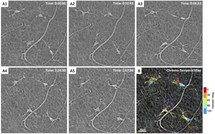
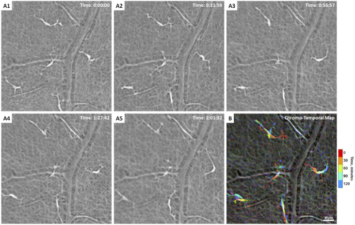
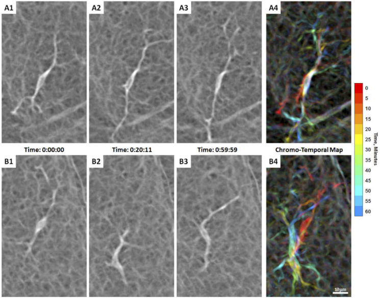
In the 2-hour imaging sessions, the total number of hyalocytes imaged at the first time point using AOSLO was 139. Of those, only the 93 cells that remain within the field of view and did not cross paths over the 2-hour window were tracked. All tracked hyalocytes exhibit cell body and processes movement throughout the two hours (Fig. 3; Visualization 1 (11.8MB, mov) & Visualization 2 (3.9MB, mov) ). Most cell bodies could be described as polygons with tapered vertices from which the processes emerged (Fig. 3) or spindle-like shape with two primary processes (Fig. 4).Therefore, a ramified cell with the presence of long and fine processes could have either a polygon-shaped or spindle-shaped cell body. To summarize the motility of these cells over time, merged emboss-filtered images obtained at different time points were coded in different colors and then merged into a single image using maximum intensity projection, creating chromo-temporal maps of the sequence of cell movements as seen on Figs. 3(B) & 4(B). These maps reveal mobile structures at specific time points in corresponding colors, while unchanged features such as capillaries appear white.
Fig. 3.
Hyalocyte shape variation and movement over 2 hours in a 28-year-old male. (A1-5) Four ramified hyalocytes remain relatively stationary while their cell bodies and processes shift in shape and orientation over time. Time of acquisition in the upper-right corner denotes the hrs:mins:secs. (B) The chromo-temporal map composites of the 5 time points that are approximately 30 minutes apart, demonstrates the movements of cell bodies and processes over 2 hours. The upper two cells display relatively greater movement of the bodies as evidenced by the visibility of different colors in the chromo-temporal map as compared to the lower cells, whose bodies appear white, indicating closer overlapping and less overall movement. The processes of all cells, however, appear to move noticeably over 2 hours. Visualization 1 (11.8MB, mov) & Visualization 2 (3.9MB, mov) show time-lapse videos of the hyalocytes and movement of their processes over 2 hours with and without cell tracking.
Fig. 4.
(A1-5) Another example of hyalocytes movement over 2 hours in a 27-year-old male ( Visualization 3 (5.9MB, mov) ). Five ramified hyalocytes with noticeable changes in shape and orientation of the cell bodies and processes over time. Time of acquisition in the upper-right corner denotes the hrs:mins:secs. (B) The chromo-temporal map composites of the 5 time points that are approximately 30 minutes apart, which indicates substantial movement of the cell bodies and processes across the imaging period. The processes of all cells appear to move noticeably over 2 hours.
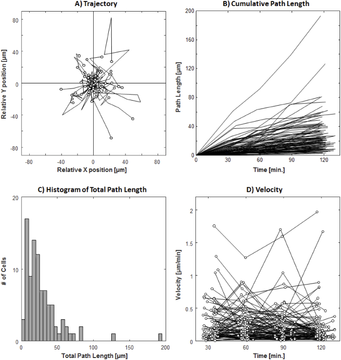
The plots of the trajectories, cumulative path lengths, and velocities of the 93 tracked cells can be seen in Fig. 5. The final cell displacement average (±SD) was 13.6 ± 13.7 µm, with a wide range of 0.6-72.0 µm over the studied 2-hour period. As indicated by the trajectory plots, many of the cells demonstrated changing travel direction and occasionally reversing course (Fig. 5(A)). This large variability in travel distance is also indicated by the total cumulative path length 28.4 ± 27.1 µm and a range of 2.9-194.1 µm (Figs. 5(B) & 5(C)). The mean velocity of all 93 cells was 0.24 ± 0.29 µm/min with a maximum velocity of 2.0 µm/min (Fig. 5(D)). Hyalocytes with large total cumulative path length showed substantial variation in velocity during different time intervals.
Fig. 5.
Trajectory, cumulative path length, and velocity plots of 93 hyalocytes tracked over 2 hours with 30-minute intervals. (A) Trajectories of all tracked hyalocytes. (B) The cumulated path length over time, regardless of the travel direction for every tracked cell. (C) Histogram of total path length measured at 2 hours (see Supplementary Fig. S4 for histograms measured at 4 time points). (D) The velocity of each cell at 30-minute intervals (see Supplementary Fig. S5 for individual velocity plots for all cells).
3.4. AOSLO imaging of hyalocyte movement over 1-hour
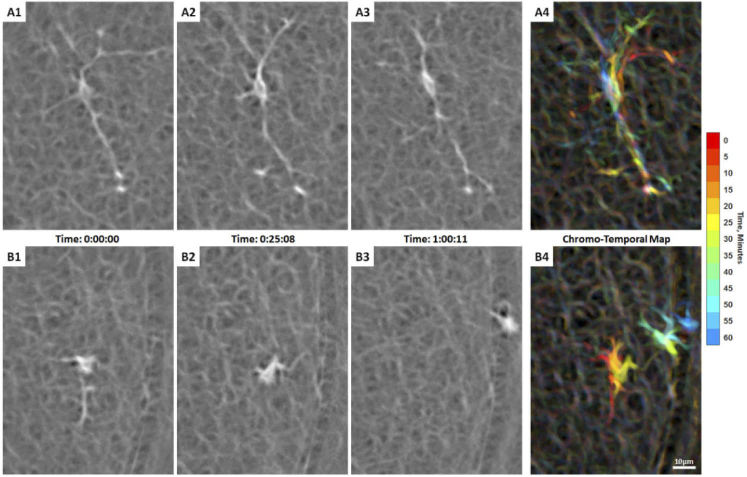
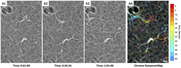
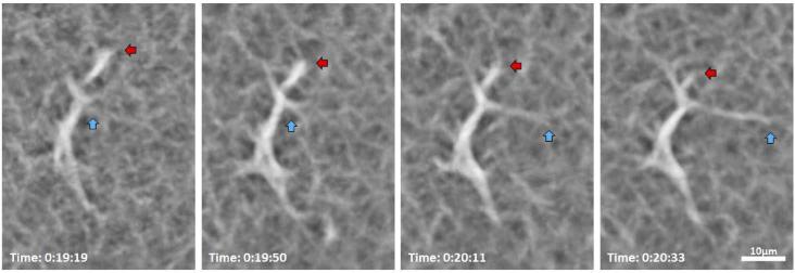
In order to visualize the movement of hyalocyte cell bodies and their processes more finely, we studied 14 cells in 3 subjects (1 subject with 4 cells and 2 subjects with 5 cells each) with AOSLO at approximately 5-minute intervals. AOSLO merged emboss-filtered time-lapse videos showed processes constantly extending, retracting, and moving across the surrounding region at the vitreoretinal interface caught at the interval of seconds to minutes, as illustrated by the sequence in Fig. 6, as well as Visualization 4 (15.4MB, mov) , Visualization 5 (18.7MB, mov) , Visualization 6 (8.2MB, mov) , Visualization 7 (8.9MB, mov) , Visualization 8 (15.2MB, mov) , and Visualization 9 (19.3MB, mov) . These highly motile processes can be appreciated by their chromatic trails in the chromo-temporal maps (Fig. 6, Fig. 8, and Fig. 9). Upon close examination of an individual cell shown in Fig. 7, a ramified hyalocyte with processes extending and retracting over 74 seconds is clearly observed.
Fig. 6.
Two adjacent hyalocytes with different movement behaviors over 1 hour of AOSLO imaging in a 32-year-old male (Visualization 4 (15.4MB, mov) ). (A1-3) A spindle-shaped cell captured at 3 time points during imaging, whose cell body remains in approximately the same location with processes moving considerably over 1 hour as indicated by the chromo-temporal map on the right (A4). (B1-3) Another cell from the same subject appears more mobile with substantial cell body displacement and shape variation over 1 hour as indicated by the chromatic trail in the chromo-temporal map (B4). Both cells appear to be in the ramified state with their thin and long processes constantly extending, retracting, and moving across the surrounding region over time. Time of acquisition of each image is displayed in hrs:mins:secs. The chromo-temporal maps are composites of 13 time points that are approximately 5 minutes apart. A video of the entire imaging ROI which includes these two cells is shown in Visualization 5 (18.7MB, mov) .
Fig. 8.
Hyalocyte movement imaged with AOSLO in a 35-year-old male ( Visualization 6 (8.2MB, mov) ). (A1-3) A spindle-shaped cell across 3 time points during imaging, whose cell body remains in approximately the same location with its thin and long processes constantly sweeping across the surroundings as indicated by the chromo-temporal map on the right (A4). (B1-3). The hyalocyte on the bottom panels displaces longer distances, while keeping a more compact, cell body shape and shorter processes as indicated by the chromo-temporal map on the right (B4), which are composites of 13 images captured ∼5 minutes apart. A video of the ROI which includes these two cells is shown in Visualization 7 (8.9MB, mov) . Time of acquisition of each image is displayed in hrs:mins:secs. (A4 & B4).
Fig. 9.
Two adjacent hyalocytes showing different movement imaged with AOSLO in a 31-year-old male ( Visualization 8 (15.2MB, mov) ). (A1-3). The lower cell appears more ramified with a spindle-like configuration whose cell body remains relatively stationary, as suggested by the white cell body color in the chromo-temporal map (A4), which is a composite of 13 images captured ∼5 minutes apart. A video of the ROI which includes these two cells is shown in Visualization 9 (19.3MB, mov) . In contrast, the upper cell has relatively shorter processes and appears more active with more substantial displacement and shape variation, as evidenced by the chromatic trail in the chromo-temporal map (A4). The dark circular features at the top left of each panel are likely microcysts, which are commonly found in sparse number throughout the retina. Time of acquisition of each image is displayed in hrs:mins:secs.
Fig. 7.
AOSLO merged emboss-filtered images show a hyalocyte with processes extending (cyan arrows) and retracting (red arrows) over 74 seconds in a 32-year-old male. Time of acquisition of each image is displayed in hrs:mins:secs. The entire image sequences of this cell over 1 hour are shown in Visualization 4 (15.4MB, mov) .
Previously described microglia cell body morphologies such as spindle-like (e.g. Visualization 7 (8.9MB, mov) , top middle cell), polygons with a few tapered vertices (e.g. Visualization 9 (19.3MB, mov) , upper right cells), rod-like (e.g. Visualization 5 (18.7MB, mov) , upper left cell), and amoeboid shapes (e.g. Visualization 9 (19.3MB, mov) , left middle cell) were observed in our AOSLO hyalocyte imaging [49–52]. While some cells maintained a relatively stable appearance over time, some cells exhibited various degrees of shape-shifting, as illustrated in Fig. 10. We also observed highly motile hyalocytes in a ramified state with multiple long processes (Fig. 6(B), Visualization 4 (15.4MB, mov) ) or activated state with less and retracted processes (Fig. 8(B), Visualization 6 (8.2MB, mov) ; Fig. 9, top cell, Visualization 8 (15.2MB, mov) ) in young healthy subjects.
Fig. 10.
Hyalocyte movement over 55 minutes imaged with AOSLO in a 31-year-old male. The cell body morphology changes from spindle-like shape to polygon with multiple vertices to triangular shape over the course of the AOSLO imaging session. Time of acquisition of each image is displayed in hrs:mins:secs The entire image sequences of this cell over 1 hour are shown in Visualization 9 (19.3MB, mov) .
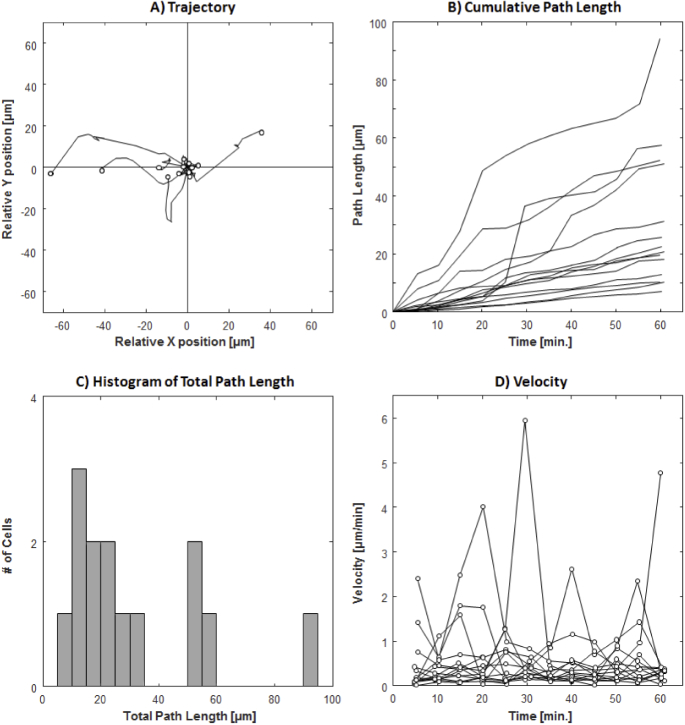
The trajectories, cumulative path lengths, and velocities measured at 5-minute intervals were plotted for all 14 tracked cells in Fig. 11. Similar to the 2-hour imaging sessions, there were large variations in the final displacement, cumulative path length, and velocity of the cells. Despite their dynamic behavior, hyalocytes appeared to position themselves in a non-overlapping fashion. Time-lapse videos of confocal and AOSLO merged emboss-filtered sequences with all acquisitions included are shown in Visualization 5 (18.7MB, mov) , Visualization 7 (8.9MB, mov) , & Visualization 9 (19.3MB, mov) . Corresponding pixel coordinates of all 14 tracked cells are provided in Dataset 1 (17.5KB, xlsx) [53], Dataset 2 (15.9KB, xlsx) [54], and Dataset 3 (23.3KB, xlsx) [55], respectively. The final displacement, cumulative path length, and velocity of hyalocytes over 1 hour and 2-hour periods are summarized in Table 2.
Fig. 11.
Trajectory, cumulative path length, and velocity plots of 14 hyalocytes tracked over 1 hour with 5-minute intervals. (A) Trajectories of all tracked hyalocytes. (B) The cumulated path length over time, irrespective of the travel direction for every tracked cell. (C) Histogram of total path length measured at 1 hour (see Supplementary Fig. S6 for histograms measured at 12 time points). (D) The velocity of each cell at 5-minute intervals (see Supplementary Fig. S7 for individual velocity plots for all cells).
Table 2. Summary measurements of hyalocyte movements.
| Final Displacement [µm] | Total Cumulative Path Length [µm] | Velocity [µm/min.] | |||||||
|---|---|---|---|---|---|---|---|---|---|
|
| |||||||||
| Mean± SD | Min. | Max. | Mean± SD | Min. | Max. | Mean± SD | Min. | Max. | |
| 2-hrs, 30 min. interval, n = 93 | 13.6±13.7 | 0.6 | 72.0 | 28.4±27.1 | 2.9 | 194.1 | 0.24±0.29 | 0.002 | 2.0 |
| 1-hr, 5 min. interval, n = 14 | 14.4±20.1 | 1.1 | 66.4 | 30.9±24.5 | 7.1 | 94.2 | 0.52±0.76 | 0.014 | 6.0 |
4. Discussion
In this study, we present label-free non-invasive imaging of vitreous cortex hyalocytes in the living human eye and their movement through the merging and filtering of non-confocal quadrant-detection AOSLO images. Based on their appearance and anterior positioning relative to the vitreoretinal interface, we believe that these cells are hyalocytes and not retinal microglia, although this should be confirmed using, for example, histochemical analysis with cell-specific labeling.
In the healthy retinas imaged in this study, these cells appeared ramified with filopodia-like processes that are constantly moving, as if surveilling their vicinity. For the most part, they appeared to operate within a relatively small area with their processes constantly extending and retracting. The cell bodies themselves also move, often as much as tens of microns over a few minutes. The movement of both cell and processes results in drastic cell body morphometry dynamics, that preclude the characterization of the cell shape or size typical of histological studies or in vivo studies of cells with geometry that remains constant in the absence of insults, such as retinal pigment epithelial cells or photoreceptors.
Previous work on retinal immune cell movement involved studying fluorescence-labeled microglia and macrophages in animal models [15,16,18,56] or ex vivo samples from animals or humans that were inspected under optical or electron microscopy [57,58]. These studies have shown that, resting microglia within the retina, can be found in a ramified state in the inner and outer plexiform layers, surrounded by tissue with similar refractive index, thus preventing in vivo visualization thus far [59]. The vitreous cortex hyalocytes are unique in that they reside above the surface of the retina, appear to have a different refractive index from that of the vitreous that surround them, allowing their visualization with OCT [11,12] and AO-OCT [19–22] without the use of fluorescent markers. In AO-OCT, these cells appear as bright punctate central cell body from which a few thin, string-like processes emerge. The cell bodies appeared round and small with respect to the span of the processes. In the merged emboss-filtered AOSLO images presented here, the hyalocytes cell body contour can be better visualized, providing better appreciation of their shape and complex transformations over time. We have observed various previously described microglia cell body morphologic appearances, including spindle-like, polygon with a few tapered vertices, rod-like, and amoeboid shapes [49–52]. In the future, the improved cell body visualization may provide additional information of cell functions such as amoeboid proprio-surveillance and phagocytosis, both which are known to alter the cell body shape.
The non-invasive imaging used here allows the observation of the movement of cells in their natural environment. An important finding in our study was that during the 5-minute interval measurements showed a wider range of cell body velocities than at 30-minute intervals (Figs. 5 & 11; Table 2), suggesting that most cells move along a fluctuating path eventually back-tracking. This is consistent with the study by Hammer et al. in which cell movement over several months was found to be similar in magnitude to the one observed here over 2 hours [22].
Unique to the merged emboss-filtered images presented here is the complex meshwork surrounding the hyalocytes. This meshwork matches the multi-strut geometry that are likely due to the retinal surface contour irregularities at the vitreoretinal interface originated from the vitreous cortex, retinal nerve fiber layer, or ILM. In scanning electron microscope imaging, the collagenous fibrils that compose the vitreous cortex [3,60] are remarkably similar to the backgrounds of our images. The meshwork feature in these images makes distinguishing the cell processes from the background quite challenging, potentially preventing automated and manual segmentation in a single image. Although not explored here, we posit that differential comparison of multiple images over time could be used to determine which pixels are part of the background and which correspond to hyalocyte cell body or processes.
When comparing AOSLO images to similarly magnified OCT images of the same cells, as shown in Fig. 2, the most striking discrepancy is the much larger apparent cell size and blunted features seen in OCT, which is to be expected, given that the poorer lateral resolution (15 µm) is close to the size of the cells, while AOSLO with the much higher lateral resolution shows a more anatomically faithful view of the cells. The larger cell size in the OCT images is also likely due to blur caused by cell movement during the 10 min which the 10 OCT volumes were captured, in contrast to the ∼18 s per AOSLO image sequence acquisition.
Our study has a few limitations and sources of error. Most importantly, the narrow field of view (1°) limited us to the tracking of the slower-moving cells that did not move out of the field of view during the sequence of recordings, either partially or completely. Cells briefly entered and/or exited the frame during part of the recordings were excluded. Secondly, the ages of our subjects were young (mean ±SD: 28.6 ± 3.7 years), preventing any exploration of age-related effects. Thirdly, the large 30 minutes intervals between measurements, probably led to an underestimation of the total path length. Finally, we do not quantify cell body or process geometry, as we have not identified suitable metrics to describe such dynamic structures and/or segment these with confidence. Future studies will target the characterization of cell movement in a diseased retinas and a larger control population.
5. Conclusion
In summary, we have demonstrated the ability to visualize hyalocytes in the living human eyes without exogenous labeling and track their movements over time using quadrant-detection AOSLO in combination with merged emboss filtering. We have also confirmed that these are the same cells we previously identified using clinical OCT instruments without adaptive optics. The characterization performed here serves as a preliminary exploration of the range of appearances and behaviors of these cells in healthy retinas. Future work will focus on the diagnostic potential of visualizing these cells in retinal diseases such as diabetic retinopathy, glaucoma, and pre-retinal membrane formation.
Acknowledgments
The content is solely the responsibility of the authors and does not necessarily represent the official views of the National Institutes of Health.
Funding
Jorge N. Buxton Microsurgical Foundation; Research to Prevent Blindness10.13039/100001818; Marrus Family Foundation10.13039/100009940; New York Eye and Ear Infirmary Foundation10.13039/100008452; National Eye Institute of the National Institutes of Health (P30EY026877, R01EY027301, R01EY031360, R01EY032147, R01EY032669).
Disclosures
Richard B. Rosen: OptoVue: Code C (Consultant) & Code P (Patent) ; Boehringer-Ingelheim: Code C (Consultant); Astellas: Code C; Genentech-Roche: Code C; NanoRetina: Code C; OD-OS: Code C; Opticology: Code I (Personal Financial Interest); Guardion: Code I (Personal Financial Interest); GlaucoHealth: Code I (Personal Financial Interest); Regeneron: Code C (Consultant); Bayer: Code C (Consultant); Teva: Code C (Consultant).
Data availability
Data underlying the results presented in this paper are available in Dataset 1 (17.5KB, xlsx) [53], Dataset 2 (15.9KB, xlsx) [54] and Dataset 3 (23.3KB, xlsx) [55].
Supplemental document
See Supplement 1 (4.1MB, pdf) for supporting content.
References
- 1.Balazs E. A., Toth L. Z., Eckl E. A., Mitchell A. P., “Studies on the structure of the vitreous body. Xii. Cytological and histochemical studies on the cortical tissue layer,” Exp Eye Res 3(1), 57–71 (1964). 10.1016/S0014-4835(64)80008-7 [DOI] [PubMed] [Google Scholar]
- 2.Vagaja N. N., Chinnery H. R., Binz N., Kezic J. M., Rakoczy E. P., McMenamin P. G., “Changes in murine hyalocytes are valuable early indicators of ocular disease,” Invest. Ophthalmol. Visual Sci. 53(3), 1445–1451 (2012). 10.1167/iovs.11-8601 [DOI] [PubMed] [Google Scholar]
- 3.Qiao H., Hisatomi T., Sonoda K. H., Kura S., Sassa Y., Kinoshita S., Nakamura T., Sakamoto T., Ishibashi T., “The characterisation of hyalocytes: The origin, phenotype, and turnover,” Br. J. Ophthalmol. 89(4), 513–517 (2005). 10.1136/bjo.2004.050658 [DOI] [PMC free article] [PubMed] [Google Scholar]
- 4.Ogawa K., “Scanning electron microscopic study of hyalocytes in the guinea pig eye,” Arch. Histol. Cytol. 65(3), 263–268 (2002). 10.1679/aohc.65.263 [DOI] [PubMed] [Google Scholar]
- 5.Sommer F., Brandl F., Weiser B., Tesmar J., Blunk T., Gopferich A., “Facs as useful tool to study distinct hyalocyte populations,” Exp Eye Res 88(5), 995–999 (2009). 10.1016/j.exer.2008.11.026 [DOI] [PubMed] [Google Scholar]
- 6.Uehara M., Imagawa T., Kitagawa H., “Morphological studies of the hyalocytes in the chicken eye: scanning electron microscopy and inflammatory response after the intravitreous injection of carbon particles,” J Anat 188(Pt 3), 661–669 (1996). [PMC free article] [PubMed] [Google Scholar]
- 7.Zhu M., Penfold P. L., Madigan M. C., Billson F. A., “Effect of human vitreous and hyalocyte-derived factors on vascular endothelial cell growth,” Aust N Z J Ophthalmol 25(4), 57–60 (1997). 10.1111/j.1442-9071.1997.tb01758.x [DOI] [PubMed] [Google Scholar]
- 8.Lazarus H. S., Hageman G. S., “In situ characterization of the human hyalocyte,” Arch. Ophthalmol. (Chicago, IL, U. S.) 112(10), 1356–1362 (1994). 10.1001/archopht.1994.01090220106031 [DOI] [PubMed] [Google Scholar]
- 9.Kohno R. I., Hata Y., Kawahara S., Kita T., Arita R., Mochizuki Y., Aiello L. P., Ishibashi T., “Possible contribution of hyalocytes to idiopathic epiretinal membrane formation and its contraction,” Br. J. Ophthalmol. 93(8), 1020–1026 (2009). 10.1136/bjo.2008.155069 [DOI] [PubMed] [Google Scholar]
- 10.Schumann R. G., Gandorfer A., Ziada J., Scheler R., Schaumberger M. M., Wolf A., Kampik A., Haritoglou C., “Hyalocytes in idiopathic epiretinal membranes: A correlative light and electron microscopic study,” Graefe's Arch. Clin. Exp. Ophthalmol. 252(12), 1887–1894 (2014). 10.1007/s00417-014-2841-x [DOI] [PubMed] [Google Scholar]
- 11.Castanos M. V., Zhou D. B., Linderman R. E., Allison R., Milman T., Carroll J., Migacz J., Rosen R. B., Chui T. Y. P., “Imaging of macrophage-like cells in living human retina using clinical oct,” Invest. Ophthalmol. Visual Sci. 61(6), 48 (2020). 10.1167/iovs.61.6.48 [DOI] [PMC free article] [PubMed] [Google Scholar]
- 12.Ong J. X., Nesper P. L., Fawzi A. A., Wang J. M., Lavine J. A., “Macrophage-like cell density is increased in proliferative diabetic retinopathy characterized by optical coherence tomography angiography,” Invest. Ophthalmol. Visual Sci. 62(10), 2 (2021). 10.1167/iovs.62.10.2 [DOI] [PMC free article] [PubMed] [Google Scholar]
- 13.Kita T., Hata Y., Miura M., Kawahara S., Nakao S., Ishibashi T., “Functional characteristics of connective tissue growth factor on vitreoretinal cells,” Diabetes 56(5), 1421–1428 (2007). 10.2337/db06-1644 [DOI] [PubMed] [Google Scholar]
- 14.Sakamoto T., Ishibashi T., “Hyalocytes: essential cells of the vitreous cavity in vitreoretinal pathophysiology?” Retina 31(2), 222–228 (2011). 10.1097/IAE.0b013e3181facfa9 [DOI] [PubMed] [Google Scholar]
- 15.Miller E. B., Zhang P., Ching K., Pugh E. N., Jr., Burns M. E., “In vivo imaging reveals transient microglia recruitment and functional recovery of photoreceptor signaling after injury,” Proc. Natl. Acad. Sci. U. S. A. 116(33), 16603–16612 (2019). 10.1073/pnas.1903336116 [DOI] [PMC free article] [PubMed] [Google Scholar]
- 16.Joseph A., Chu C. J., Feng G., Dholakia K., Schallek J., “Label-free imaging of immune cell dynamics in the living retina using adaptive optics,” eLife 9, e60547 (2020). 10.7554/eLife.60547 [DOI] [PMC free article] [PubMed] [Google Scholar]
- 17.Qin Z., He S., Yang C., Yung J. S., Chen C., Leung C. K., Liu K., Qu J. Y., “Adaptive optics two-photon microscopy enables near-diffraction-limited and functional retinal imaging in vivo,” Light: Sci. Appl. 9(1), 79 (2020). 10.1038/s41377-020-0317-9 [DOI] [PMC free article] [PubMed] [Google Scholar]
- 18.Joseph A., Power D., Schallek J., “Imaging the dynamics of individual processes of microglia in the living retina in vivo,” Biomed. Opt. Express 12(10), 6157–6183 (2021). 10.1364/BOE.426157 [DOI] [PMC free article] [PubMed] [Google Scholar]
- 19.Liu Z., Kurokawa K., Zhang F., Lee J. J., Miller D. T., “Imaging and quantifying ganglion cells and other transparent neurons in the living human retina,” Proc. Natl. Acad. Sci. U. S. A. 114(48), 12803–12808 (2017). 10.1073/pnas.1711734114 [DOI] [PMC free article] [PubMed] [Google Scholar]
- 20.Liu Z., Tam J., Saeedi O., Hammer D. X., “Trans-retinal cellular imaging with multimodal adaptive optics,” Biomed. Opt. Express 9(9), 4246–4262 (2018). 10.1364/BOE.9.004246 [DOI] [PMC free article] [PubMed] [Google Scholar]
- 21.Kurokawa K., Crowell J. A., Zhang F., Miller D. T., “Suite of methods for assessing inner retinal temporal dynamics across spatial and temporal scales in the living human eye,” Neurophotonics 7(01), 1 (2020). 10.1117/1.NPh.7.1.015013 [DOI] [PMC free article] [PubMed] [Google Scholar]
- 22.Hammer D. X., Agrawal A., Villanueva R., Saeedi O., Liu Z., “Label-free adaptive optics imaging of human retinal macrophage distribution and dynamics,” Proc. Natl. Acad. Sci. U. S. A. 117(48), 30661–30669 (2020). 10.1073/pnas.2010943117 [DOI] [PMC free article] [PubMed] [Google Scholar]
- 23.Liang J., Williams D. R., Miller D. T., “Supernormal vision and high-resolution retinal imaging through adaptive optics,” J. Opt. Soc. Am. A 14(11), 2884–2892 (1997). 10.1364/JOSAA.14.002884 [DOI] [PubMed] [Google Scholar]
- 24.Dubra A., Sulai Y., Norris J. L., Cooper R. F., Dubis A. M., Williams D. R., Carroll J., “Noninvasive imaging of the human rod photoreceptor mosaic using a confocal adaptive optics scanning ophthalmoscope,” Biomed. Opt. Express 2(7), 1864–1876 (2011). 10.1364/BOE.2.001864 [DOI] [PMC free article] [PubMed] [Google Scholar]
- 25.Chui T. Y., Vannasdale D. A., Burns S. A., “The use of forward scatter to improve retinal vascular imaging with an adaptive optics scanning laser ophthalmoscope,” Biomed. Opt. Express 3(10), 2537–2549 (2012). 10.1364/BOE.3.002537 [DOI] [PMC free article] [PubMed] [Google Scholar]
- 26.Scoles D., Sulai Y. N., Dubra A., “In vivo dark-field imaging of the retinal pigment epithelium cell mosaic,” Biomed. Opt. Express 4(9), 1710–1723 (2013). 10.1364/BOE.4.001710 [DOI] [PMC free article] [PubMed] [Google Scholar]
- 27.Dubow M., Pinhas A., Shah N., Cooper R. F., Gan A., Gentile R. C., Hendrix V., Sulai Y. N., Carroll J., Chui T. Y. P., Walsh J. B., Weitz R., Dubra A., Rosen R. B., “Classification of human retinal microaneurysms using adaptive optics scanning light ophthalmoscope fluorescein angiography,” Invest. Ophthalmol. Visual Sci. 55(3), 1299–1309 (2014). 10.1167/iovs.13-13122 [DOI] [PMC free article] [PubMed] [Google Scholar]
- 28.Scoles D., Higgins B. P., Cooper R. F., Dubis A. M., Summerfelt P., Weinberg D. V., Kim J. E., Stepien K. E., Carroll J., Dubra A., “Microscopic inner retinal hyper-reflective phenotypes in retinal and neurologic disease,” Invest. Ophthalmol. Visual Sci. 55(7), 4015–4029 (2014). 10.1167/iovs.14-14668 [DOI] [PMC free article] [PubMed] [Google Scholar]
- 29.Huang G., Luo T., Gast T. J., Burns S. A., Malinovsky V. E., Swanson W. H., “Imaging glaucomatous damage across the temporal raphe,” Invest. Ophthalmol. Vis. Sci. 56(6), 3496–3504 (2015). 10.1167/iovs.15-16730 [DOI] [PMC free article] [PubMed] [Google Scholar]
- 30.Beykin G., Norcia A. M., Srinivasan V. J., Dubra A., Goldberg J. L., “Discovery and clinical translation of novel glaucoma biomarkers,” Prog. Retinal Eye Res. 80, 100875 (2021). 10.1016/j.preteyeres.2020.100875 [DOI] [PMC free article] [PubMed] [Google Scholar]
- 31.Sredar N., Razeen M., Kowalski B., Carroll J., Dubra A., “Comparison of confocal and non-confocal split-detection cone photoreceptor imaging,” Biomed. Opt. Express 12(2), 737–755 (2021). 10.1364/BOE.403907 [DOI] [PMC free article] [PubMed] [Google Scholar]
- 32.Chui T. Y., Gast T. J., Burns S. A., “Imaging of vascular wall fine structure in the human retina using adaptive optics scanning laser ophthalmoscopy,” Invest. Ophthalmol. Vis. Sci. 54(10), 7115–7124 (2013). 10.1167/iovs.13-13027 [DOI] [PMC free article] [PubMed] [Google Scholar]
- 33.Rossi E. A., Granger C. E., Sharma R., Yang Q., Saito K., Schwarz C., Walters S., Nozato K., Zhang J., Kawakami T., Fischer W., Latchney L. R., Hunter J. J., Chung M. M., Williams D. R., “Imaging individual neurons in the retinal ganglion cell layer of the living eye,” Proc. Natl. Acad. Sci. U. S. A. 114(3), 586–591 (2017). 10.1073/pnas.1613445114 [DOI] [PMC free article] [PubMed] [Google Scholar]
- 34.Scoles D., Sulai Y. N., Langlo C. S., Fishman G. A., Curcio C. A., Carroll J., Dubra A., “In vivo imaging of human cone photoreceptor inner segments,” Invest. Ophthalmol. Vis. Sci. 55(7), 4244–4251 (2014). 10.1167/iovs.14-14542 [DOI] [PMC free article] [PubMed] [Google Scholar]
- 35.Mozaffari S., Jaedicke V., LaRocca F., Tiruveedhula P., Roorda A., “Versatile multi-detector scheme for adaptive optics scanning laser ophthalmoscopy,” Biomed. Opt. Express 9(11), 5477–5488 (2018). 10.1364/BOE.9.005477 [DOI] [PMC free article] [PubMed] [Google Scholar]
- 36.Sapoznik K. A., Luo T., de Castro A., Sawides L., Warner R. L., Burns S. A., “Enhanced retinal vasculature imaging with a rapidly configurable aperture,” Biomed. Opt. Express 9(3), 1323–1333 (2018). 10.1364/BOE.9.001323 [DOI] [PMC free article] [PubMed] [Google Scholar]
- 37.Mecê P., Gofas-Salas E., Rui Y., Zhang M., Sahel J.-A., Rossi E. A., “Spatial-frequency-based image reconstruction to improve image contrast in multi-offset adaptive optics ophthalmoscopy,” Opt. Lett. 46(5), 1085–1088 (2021). 10.1364/OL.417903 [DOI] [PMC free article] [PubMed] [Google Scholar]
- 38.Gofas-Salas E., Rui Y., Mecê P., Zhang M., Snyder V. C., Vienola K. V., Lee D. M. W., Sahel J.-A., Grieve K., Rossi E. A., “Design of a radial multi-offset detection pattern for in vivo phase contrast imaging of the inner retina in humans,” Biomed. Opt. Express 13(1), 117–132 (2022). 10.1364/BOE.441808 [DOI] [PMC free article] [PubMed] [Google Scholar]
- 39.Guevara-Torres A., Williams D. R., Schallek J. B., “Origin of cell contrast in offset aperture adaptive optics ophthalmoscopy,” Opt. Lett. 45(4), 840–843 (2020). 10.1364/OL.382589 [DOI] [PMC free article] [PubMed] [Google Scholar]
- 40.Dubra A., Sulai Y., “Reflective afocal broadband adaptive optics scanning ophthalmoscope,” Biomed. Opt. Express 2(6), 1757–1768 (2011). 10.1364/BOE.2.001757 [DOI] [PMC free article] [PubMed] [Google Scholar]
- 41.Sulai Y. N., Scoles D., Harvey Z., Dubra A., “Visualization of retinal vascular structure and perfusion with a nonconfocal adaptive optics scanning light ophthalmoscope,” J. Opt. Soc. Am. A 31(3), 569–579 (2014). 10.1364/JOSAA.31.000569 [DOI] [PMC free article] [PubMed] [Google Scholar]
- 42.Kraus M. F., Potsaid B., Mayer M. A., Bock R., Baumann B., Liu J. J., Hornegger J., Fujimoto J. G., “Motion correction in optical coherence tomography volumes on a per a-scan basis using orthogonal scan patterns,” Biomed. Opt. Express 3(6), 1182–1199 (2012). 10.1364/BOE.3.001182 [DOI] [PMC free article] [PubMed] [Google Scholar]
- 43.Dubra A., Harvey Z., “Registration of 2d images from fast scanning ophthalmic instruments,” in Biomedical Image Registration (Springer, 2010), pp. 60–71. [Google Scholar]
- 44.Schneider C. A., Rasband W. S., Eliceiri K. W., “Nih image to imagej: 25 years of image analysis,” Nat. Methods 9(7), 671–675 (2012). 10.1038/nmeth.2089 [DOI] [PMC free article] [PubMed] [Google Scholar]
- 45.Arganda-Carreras I., Sorzano C. O. S., Marabini R., Carazo J. M., Ortiz-de-Solorzano C., Kybic J., “Consistent and elastic registration of histological sections using vector-spline regularization,” in Computer Vision Approaches to Medical Image Analysis (Springer, 2006), pp. 85–95. [Google Scholar]
- 46.Tinevez J. Y., Perry N., Schindelin J., Hoopes G. M., Reynolds G. D., Laplantine E., Bednarek S. Y., Shorte S. L., Eliceiri K. W., “Trackmate: an open and extensible platform for single-particle tracking,” Methods 115, 80–90 (2017). 10.1016/j.ymeth.2016.09.016 [DOI] [PubMed] [Google Scholar]
- 47.Mo S., Phillips E., Krawitz B. D., Garg R., Salim S., Geyman L. S., Efstathiadis E., Carroll J., Rosen R. B., Chui T. Y., “Visualization of radial peripapillary capillaries using optical coherence tomography angiography: the effect of image averaging,” PLoS One 12, e0169385 (2017). 10.1371/journal.pone.0169385 [DOI] [PMC free article] [PubMed] [Google Scholar]
- 48.Chui T. Y., Zhong Z., Song H., Burns S. A., “Foveal avascular zone and its relationship to foveal pit shape,” Optom. Vis. Sci. 89(5), 602–610 (2012). 10.1097/OPX.0b013e3182504227 [DOI] [PMC free article] [PubMed] [Google Scholar]
- 49.Taylor S. E., Morganti-Kossmann C., Lifshitz J., Ziebell J. M., “Rod microglia: a morphological definition,” PLoS One 9(5), e97096 (2014). 10.1371/journal.pone.0097096 [DOI] [PMC free article] [PubMed] [Google Scholar]
- 50.Davis B. M., Salinas-Navarro M., Cordeiro M. F., Moons L., De Groef L., “Characterizing microglia activation: a spatial statistics approach to maximize information extraction,” Sci. Rep. 7(1), 1576 (2017). 10.1038/s41598-017-01747-8 [DOI] [PMC free article] [PubMed] [Google Scholar]
- 51.Li F., Jiang D., Samuel M. A., “Microglia in the developing retina,” Neural Dev 14(1), 12 (2019). 10.1186/s13064-019-0137-x [DOI] [PMC free article] [PubMed] [Google Scholar]
- 52.Choi S., Guo L., Cordeiro M. F., “Retinal and brain microglia in multiple sclerosis and neurodegeneration,” Cells 10(6), 10 (2021). 10.3390/cells10061507 [DOI] [PMC free article] [PubMed] [Google Scholar]
- 53.Migacz J., “Dataset 1,” figshare (2021), retrieved boe-13-3-1755-d001.xlsx.
- 54.Migacz J., “Dataset 2,” figshare (2021), retrieved boe-13-3-1755-d002.xlsx.
- 55.Migacz J., “Dataset 3,” figshare (2021), retrieved boe-13-3-1755-d003.xlsx.
- 56.Alt C., Runnels J. M., Mortensen L. J., Zaher W., Lin C. P., “In vivo imaging of microglia turnover in the mouse retina after ionizing radiation and dexamethasone treatment,” Invest. Ophthalmol. Vis. Sci. 55(8), 5314–5319 (2014). 10.1167/iovs.14-14254 [DOI] [PubMed] [Google Scholar]
- 57.Grabner G., Boltz G., Forster O., “Macrophage-like properaties of human hyalocytes,” Invest. Ophthalmol. Vis. Sci. 19, 333–340 (1980). [PubMed] [Google Scholar]
- 58.Nolte C., Moller T., Walter T., Kettenmann H., “Complement 5a controls motility of murine microglial cells in vitro via activation of an inhibitory g-protein and the rearrangement of the actin cytoskeleton,” Neuroscience 73(4), 1091–1107 (1996). 10.1016/0306-4522(96)00106-6 [DOI] [PubMed] [Google Scholar]
- 59.Miller D. T., Kurokawa K., “Cellular-scale imaging of transparent retinal structures and processes using adaptive optics optical coherence tomography,” Annu. Rev. Vis. Sci. 6(1), 115–148 (2020). 10.1146/annurev-vision-030320-041255 [DOI] [PMC free article] [PubMed] [Google Scholar]
- 60.Sebag J., The Vitreous - Structure, Function, and Pathobiology (Springer-Verlag, 1989), pp. 43–54 [Google Scholar]
Associated Data
This section collects any data citations, data availability statements, or supplementary materials included in this article.
Data Citations
- Migacz J., “Dataset 1,” figshare (2021), retrieved boe-13-3-1755-d001.xlsx.
- Migacz J., “Dataset 2,” figshare (2021), retrieved boe-13-3-1755-d002.xlsx.
- Migacz J., “Dataset 3,” figshare (2021), retrieved boe-13-3-1755-d003.xlsx.
Data Availability Statement
Data underlying the results presented in this paper are available in Dataset 1 (17.5KB, xlsx) [53], Dataset 2 (15.9KB, xlsx) [54] and Dataset 3 (23.3KB, xlsx) [55].


