

Abstract
Objective:
To determine the forces and moments delivered to a maxillary central incisor during rotation by three different thermoplastic appliances with identical thickness.
Materials and Methods:
Five identical appliances were manufactured from each of three materials (Ideal Clear 1.0 mm, Erkodur 1.0 mm, Biolon 1.0 mm). An upper central incisor fixed in a measuring device was rotated around its central axis in 0.5-degree steps to ±2.5 degrees, ±5 degrees, and ±7.5 degrees (equivalent to an activation of ±0.17 mm, ±0.34 mm, and ±0.51 mm of the incisor edge) in the clockwise and anticlockwise directions with the respective appliance fixed in place. For statistical analysis, the moments Tz (rotation) and forces Fz (intrusion) were tested. Means and standard deviations for Tz and median and 25% and 75% quantiles for Fz were calculated. An analysis of variance (ANOVA) was performed.
Results:
The minimal moment was determined at a rotation of −0.17 mm (−7.3 Nmm, ±0.8), and the maximal moment at a deflection of −0.51 mm (−71.8 Nmm. ±2.5) was recorded. The minimal value for Fz was measured at an activation of −0.17 mm (0.0 N), and the highest intrusive forces were evaluated for a rotation of −0.51 mm (−5.8 N). The particular material sometimes had a significant (P < .05) influence on the forces delivered and the moments.
Conclusions:
During rotation with aligners, an intrusive force can also be observed. The direction of rotation, and the materials used all exert an influence on the force delivery properties of the appliance.
Keywords: Thermoplastic appliances, Forces and moments
INTRODUCTION
The use of thermoplastic appliances is primarily recommended for mild malocclusions, and it is often used successfully for alignment of the mandibular and maxillary anterior teeth.1,2 In this context, treatment must frequently be given for rotations of the teeth, and this form of treatment has been reported to be one of the most accurate and highly predictable types of tooth movement with aligners.2,3
Even though the movement of teeth with thermoplastic appliances has been clinically documented, the force delivery properties of these appliances have only been evaluated in a few in vivo4 and in vitro studies of tipping movement.5,6
The aim of the present study was to evaluate the forces and moments exerted by removable thermoplastic appliances produced by three different, hard thermoplastic materials, with the same thickness, on a maxillary central incisor during rotation in vitro.
MATERIALS AND METHODS
The measurements were carried out with a newly developed modular measuring device, which was described in detail recently.5 It was constructed for modular use and is composed of a quadrangular frame rigidly coupled on a base-plate by four posts. A resin bowl can be reversibly fixed in the frame by a locking screw. A standardized resin model (Frasaco GmbH, Tettnang, Germany), with the separated maxillary central incisor as the measuring tooth, was fixed by plaster in the resin bowl. The measuring tooth itself was fixed on the sensor (Nano 17 sensor, ATI Industrial Automation, Apex, NC) by a clamp. The sensor was again positioned on a rotary stage (DT 130, OWIS GmbH, Staufen, Germany) for rotating the measuring tooth. The rotary stage, in turn, was fixed by an additional aluminum frame on the base-plate (Figure 1). The complete measuring device could be moved into a climate chamber to simulate oral moisture and temperature conditions.
Figure 1.
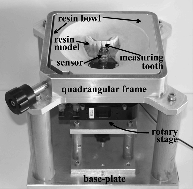
Basic elements of the measuring device used (modified after Hahn et al6).
After installation of the measuring device, one impression (Tetrachrom, Kanidenta, Herford, Germany) with the measuring tooth in the neutral position was made, and subsequently a plaster model was produced with GC Fujirock EP (GC Germany GmbH, Munich, Germany). This model was trimmed to a height of 20 mm parallel to the occlusal plane and 15 identical plaster copies (GC Fujirock EP) of the model were finally made using Adisil blue 9∶1 (SILADENT Dr. Böhme & Schöps GmbH, Goslar, Germany). Five equally extended appliances were constructed on these models from each material evaluated.
The materials and forming machines used were Biolon 1.0 mm (Dreve Dentamid GmbH, Unna, Germany) with Drufomat-TE (Dreve Dentamid), Erkodur 1.0 mm (Erkodent Erich Kopp GmbH, Pfalzgrafenweiler, Germany) with Erkoform RVE (Erkodent Erich Kopp), and Ideal Clear 1.0 mm (Dentsply GAC, Gräfelfing, Germany) with Vacuum-forming Machine 202 (Dentsply GAC, Bohemia, NY).
Measurements were carried out at 37°C in the drying chamber. The inner surfaces of the appliances were moistened with artificial saliva (University Pharmacy, Goettingen, Germany). The forces and moments measured by the sensor were set to zero before starting the measuring cycle.
For measuring the forces and moments delivered during rotation, the tooth was rotated along its central axis (center of the incisor edge and the root) in a clockwise direction from 0 degrees to 10 degrees and back to 0 degrees in 0.5-degree steps and then in an anticlockwise direction from 0 degrees to −10 degrees and back to 0 degrees in 0.5-degree steps. The measurements were recorded five times after each step. All six components of forces and moments (Fx, Fy, Fz, Tx, Ty, Tz) were measured. For the comparison of the three materials, values for the intrusive force Fz and the rotational moment Tz at the angles of ±2.5 degrees, ±5 degrees, and ±7.5 degrees were used. To provide a more illuminating comparison with results available in the literature for comparable measurements, the angular degrees were converted into distance moved in millimeters from the mesial and distal endpoint of the incisor edge, respectively (±0.17 mm, ±0.34 mm, and ±0.51 mm). The first two values are comparable to the lower and upper limit for an activation range given in the literature for the Invisalign appliance (0.15 mm and 0.33 mm, respectively),2,7 whereas the third value was approximately comparable to the programmed distance in the Clear Smile appliance (0.5 mm).4
Statistical Analysis
Because hysteresis could be observed, for further analysis only the Fz and Tz values measured during increasing rotation in a particular direction were used.
The forces (Fz) and moments (Tz) measured at a particular activation range (±0.17 mm, ±0.34 mm, and ±0.51 mm) were compared among the three materials by analysis of variance (ANOVA) for repeated measurements. Because Fz values showed a skewed distribution, a nonparametric version of ANOVA was utilized for the analysis, whereas Tz values were analyzed with the classical parametric ANOVA. Assumptions regarding distributions were checked by means of quantile-quantile plots. Accordingly, Tz values were described by means (±SE) and Fz values by medians (25% and 75% quantiles). Analyses of variance were performed with SAS (version 9.1, SAS Institute, Chicago, Ill). The significance level was set to α = .05 for all tests.
RESULTS
A typical load-deflection diagram illustrated for one material (Biolon), as produced for all six components (Fx, Fy, Fz, Tx, Ty, Tz) during a measuring cycle is given in Figure 2. Even though Fx and Fy, as well as Tx and Ty, show measurable changes, the eye-catching course of the curves in terms of the height of the values and their regularity can be observed for the values Fz and Tz.
Figure 2.
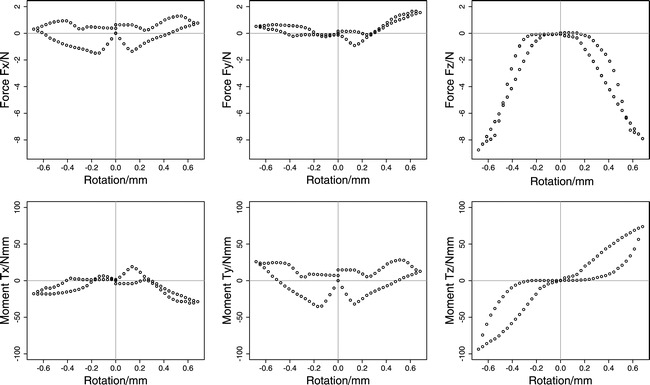
Typical measured forces (Fx, Fy, Fz) and moments (Tx, Ty, Tz) during a full rotation cycle in the clockwise and anticlockwise directions illustrated with one material (Biolon).
The means and standard deviations for the moment Tz at the respective distances moved are given for each material in Table 1. The corresponding results for Fz are shown in Table 2 by the median (50% quantile) and the 25% and 75% quantiles.
Table 1.
Mean and Standard Error (SE) for the Moment Tz (Nmm) for the Particular Activation Ranges for Each Material Evaluated
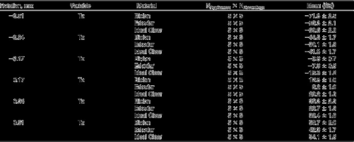
Table 2.
Median (50% Quantile) and 25% and 75% Quantiles for the Force Fz (N) at the Particular Rotation Ranges for Each Material Evaluated

The results for the comparison of the corresponding samples are shown in Tables 3 and 4. The corresponding box plots are illustrated in Figures 3 and 4.
Table 3.
Results of Pair-wise Analyses of Variance (ANOVA) for the Moment Tz for the Materials Evaluated (Biolon, Erkodur, and Ideal Clear) and for the Particular Activation Ranges (±0.17 mm, ±0.34 mm, and ±0.51 mm)
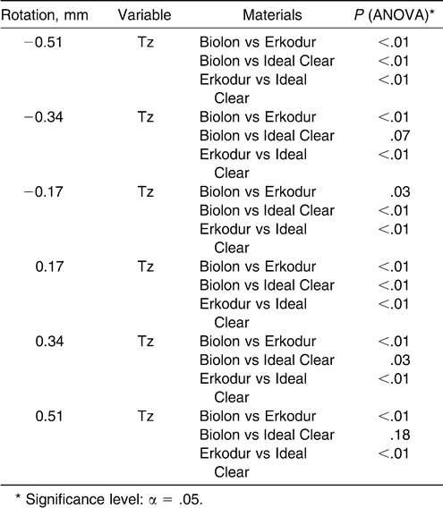
Table 4.
Results of Pair-wise Analyses of Variance (ANOVA) for the Force Fz for the Materials Evaluated (Biolon, Erkodur, and Ideal Clear) and for the Particular Activation Ranges (±0.17 mm, ±0.34 mm, and ±0.51 mm)
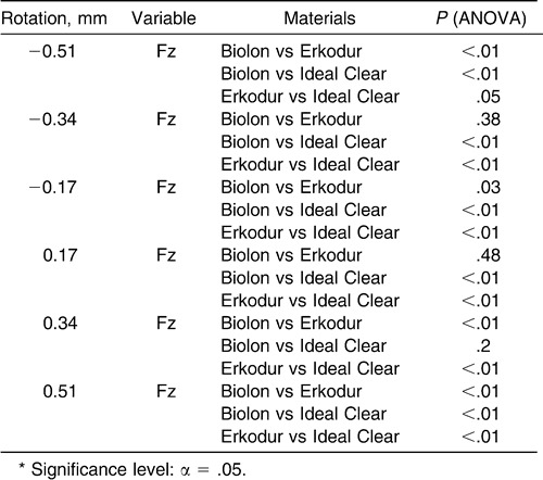
Figure 3.
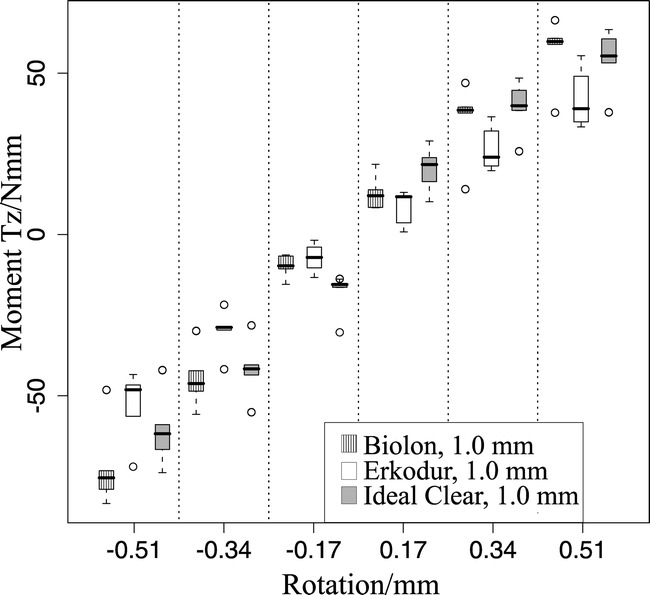
Box plots specifying the measured moments Tz/Nmm for each evaluated material at the respective activation ranges (±0.17 mm, ±0.34 mm, and ±0.51 mm).
Figure 4.

Box plots specifying the measured forces Fz/N for each evaluated material at the respective activation ranges (±0.17 mm, ±0.34 mm, and ±0.51 mm).
At the lower rotation range of ±0.17 mm, the Ideal Clear appliances showed the highest values for Tz (−18.3 Nmm [±1.2], 20.2 Nmm [±1.3]) (Table 1). The differences between the appliances according to Tz at this movement range were statistically significant (P < .01, Biolon vs Erkodur, P = .03) (Table 3).
At the high rotation range of ±0.51 mm, the Biolon appliance delivered the highest moments (Tz: −71.8 Nmm [±2.5], +56.7 Nmm [±2.0]) (Table 1). These values were almost always significantly different from those for the other materials (P < .01), except for the Biolon vs Ideal Clear comparison (P = .18) (Table 3). The lowest rotational moments were always measured for the Erkodur appliances at all activation ranges (Tz at ± 0.17 mm: −7.3 Nmm [±0.8], +8.2 Nmm [±1.0]; Tz at ±0.51 mm: −53.3 Nmm [±2.1], 42.3 Nmm [±1.7]) (Table 1). The values for the Erkodur appliances were always significantly different from those of the other materials (P < .01; Tz at ±0.17 mm, Biolon vs Erkodur, P = .03) (Table 3).
The median values for Fz at the low activation range of ±0.17 mm are calculated to be between 0.0 N (−0.17 mm, Biolon) and −0.8 N (0.17 mm, Ideal Clear) (Table 2). The Fz values measured when delivered by the Ideal Clear appliances at this low activation range were significantly higher than those for the other two materials evaluated (P < .01) (Table 4).
The highest median values for Fz were evaluated for the Biolon appliances at the distance moved of ±0.51 mm (−0.51 mm: Fz = −5.8 N; +0.51 mm: Fz = −5.2 N) (Table 2). These values for Fz at this movement range are significantly higher than the corresponding values for the other two materials (P < .01) (Table 4).
DISCUSSION
Until now, it has been almost impossible to simulate the periodontal tissues in an in vitro reconstruction taking the local stresses and strains and the viscoelastic and multiphasic properties of the periodontal ligament into account. Therefore, in vitro research on orthodontic forces has mainly been restricted to an experimental set-up such as that used in the present study. Consequently, the values measured are initial ones when no rapid tooth movement can be expected.8–12
The axial moment Tz is produced by two horizontal forces acting in opposite directions, which are generated when the crown is rotated against the vestibular and palatal inner surfaces of the appliance. In an idealized situation, the two forces would cancel each other and a pure moment would remain. But, when considering Figure 2, the values for Fx and Fy demonstrate that, during the measuring cycle, constantly acting, horizontal forces are still present. This can be explained by the complex shape of the crown with, for example, a palatal concavity and a vestibular convexity. As a consequence, continuously changing, uneven forces on the vestibular and palatal side during rotation are to be expected (Figures 2 and 5).
Figure 5.
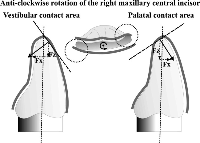
The tooth is rotated anticlockwise prior to therapy around its central axis (long dotted vertical line). Two major contact areas in the vestibular and palatal directions between the crown and the inner surfaces of the appliance result (dotted circles). Because of the convergently inclined walls of the appliance in the vestibular and palatal contact areas (dotted tangent lines), vertical (Fz) and horizontal (Fx) force components result. Since the inclinations of the tangents are different on both sides, the norms of the respective vector components (Fx, Fz) are also different on both sides. Consequently, there is no pure rotation, but tipping also occurs.
The Tz values are difficult to compare with those reported in the literature as being ideal for axial rotation. Instead of moments, Proffit13 gave force values as standard values between 0.35 and 0.6 N, such as for tipping, which were mainly exceeded by the results measured. According to Proffit,13 it is almost impossible to create pure rotation. The tooth would always also tip in its socket and, therefore, an area of compression would be created. This argument seems to apply also to the use of thermoplastic appliances because tipping forces (Fx, Fy) could be measured during the whole rotation cycle in the present study (Figure 2). Nevertheless, it has also been reported in the literature that values for moments about ±15 Nmm occur during therapy with fixed appliances.14,15 These values were just maintained with the present measurements at an activation of ±0.17 mm. When the tooth was rotated more, the values were approximately two to four and a half times higher.
During the axial rotation, an intrusive force could also be measured which has already been described as being a general phenomenon associated with thermoplastic appliances as “the watermelon seed effect.”16 Comparable values and Fz values about three times higher than those measured in the present study have been reported before, for the same materials, during tipping of 0.151 mm.5 These intrusive force can be explained by a local deformation of the inclined inner surfaces of the appliance (Figure 5) and with a reduced fit during progressive axial rotation, which tends to deform the appliance like a bow, by raising it in the anterior region. As a consequence, a reactive force Fz is generated that acts vertically on the tooth.
The median Fz values were measured between 0 N and −5.8 N. Even at a deflection of ±0.17 mm, the values given by Proffit13 as being ideal for intrusion (0.1–0.2 N) are mostly exceeded by two to two and a half times. When the tooth was rotated up to ±0.34 mm and ±0.51 mm, respectively, the over step was approximately up to 25 times. As reported in the literature, especially for intrusion, low force levels are desired,13 but it is still unclear whether root resorption caused by large forces is a particular problem with thermoplastic appliances.17–19 Nevertheless, the forces at the lower range of activation are of lesser relevance, because the amount of movement is adapted to the width of the periodontal ligament (0.1–0.3 mm).20,21 As postulated before,5,6 a self-protecting mechanism might be responsible for a low rate of root resorption, even with appliances with an initial activation range of over 0.2 mm.4,17–19 This mechanism is probably based on the reduced fit of the appliance during increased activation. As a consequence, full activation would not become operative and, in fact, the large measured forces could be due to lower activation ranges than originally intended.
As a general phenomenon, in the present study, the forces and moments for anticlockwise activation were larger than for clockwise rotation. A potential rationale for this might be the different crown forms of the measuring tooth in the mesial and distal directions and the different shapes and sizes of neighboring teeth mesial and distal. Consequently, the appliance is molded differently on the mesial and distal proximity of the measuring tooth and, therefore, the respective forces delivered in these areas are probably different. This suggests that the complex force delivery properties of thermoplastic appliances are additionally influenced by the position and shape of the teeth adjacent to the tooth which it is intended to move.
As a trend, compared to the other two materials, the vacuum-formed Biolon appliances produced greater moments and forces at the higher rates of activation. On the other hand, the forces and moments delivered by the vacuum formed Ideal Clear appliances were higher at the low activation ranges. All in all, the forces and moments delivered by the vacuum-formed Erkodur appliances were always the lowest.
At lower activation ranges, different chemical and physical material properties (according to the manufacturers' information: Biolon = polyethylene terephthalate, Erkodur and Ideal Clear = glycol-modified polyethylene terephthalate) might be responsible for the different force levels. At these ranges, the local deformations of the material and friction phenomena at the contact areas are perhaps of greater relevance. Whereas at higher activation ranges when the appliance gets progressively lifted up in the anterior region, the friction of the appliance that acts against this lifting up in the posterior region is probably of more importance. This friction is probably influenced by the particular thermoforming process. While, for example, the Erkodur appliances are vacuum-formed with a vacuum of 0.8 bar, the Biolon appliances are pressure-formed with a pressure of 6 bar. For the Erkodur appliances, whose values are always lower, a further spacing foil between tooth and appliance that is removed after thermoforming could have a certain influence. Nevertheless, this foil has, according to the manufacturers' information, a thickness before thermoforming of 0.05 mm. This will be reduced after thermoforming by a certain amount. Overall, the thickness of this foil after thermoforming is probably comparable to the distance moved by one activation step in the present study. A further indication of a probably reduced relevance of the spacing foil on force values in the Erkodur appliances is that because at the low activation range of ±0.17 mm when the influence due to the small distance moved might be of greater relevance, the Erkodur appliances delivered higher Fz forces than the Biolon appliances. Finally, it remains somewhat unclear which specific material-dependent effect is relevant for the forces and moments delivered at a particular activation range.
CONCLUSIONS
During rotation of the maxillary central incisor, an intrusive force could be measured despite the rotating moment.
The measured forces and moments are higher than those recommended in the literature. But, according to the literature, potential biologic adverse effects remain unclear.
Due to the complex shape of the crown, no pure moments and also continuously acting and changing horizontal forces could be measured.
Also, the particular materials with their corresponding thermoforming processes had a measurable effect on the forces delivered. These observations illustrate once more the multiple factors influencing the force delivery properties of thermoplastic appliances.
REFERENCES
- 1.Kuncio D, Maganzini A, Shelton C, Freeman K. Invisalign and traditional orthodontic treatment postretention outcomes compared using the American Board of Orthodontics objective grading system. Angle Orthod. 2007;77:864–869. doi: 10.2319/100106-398.1. [DOI] [PubMed] [Google Scholar]
- 2.Kravitz N. D, Kusnoto B, BeGole E, Obrez A, Agran B. How well does Invisalign work? A prospective clinical study evaluating the efficacy of tooth movement with Invisalign. Am J Orthod Dentofacial Orthop. 2009;135:27–35. doi: 10.1016/j.ajodo.2007.05.018. [DOI] [PubMed] [Google Scholar]
- 3.Boyd R. Predictability of successful orthodontic treatment using Invisalign. Available at: http://www.gpso.org/events/2003_outline.pdf Accessed February 27, 2009. [Google Scholar]
- 4.Barbagallo L. J, Shen G, Jones A. S, Swain M. V, Petocz P, Darendeliler M. A. A novel pressure film approach for determining the force imparted by clear removable thermoplastic appliances. Ann Biomed Eng. 2008;36:335–341. doi: 10.1007/s10439-007-9424-5. [DOI] [PubMed] [Google Scholar]
- 5.Hahn W, Fialka-Fricke J, Dathe H, Fricke-Zech S, Zapf A, Gruber R, Kubein-Meesenburg D, Sadat-Khonsari R. Initial forces generated by three types of thermoplastic appliances on an upper central incisor during tipping. Eur J Orthod. In press doi: 10.1093/ejo/cjp047. [DOI] [PubMed] [Google Scholar]
- 6.Hahn W, Dathe H, Fialka-Fricke J, Fricke-Zech S, Zapf A, Kubein-Meesenburg D, Sadat-Khonsari R. Influence of thermoplastic appliances' thickness on the magnitude of force delivered to an upper central incisor during tipping. Am J Orthod Dentofacial Orthop. In press doi: 10.1016/j.ajodo.2008.12.015. [DOI] [PubMed] [Google Scholar]
- 7.Boyd R. L, Vlascalic V. Three-dimensional diagnosis and orthodontic treatment of complex malocclusions with the Invisalign appliance. Semin Orthod. 2001;7:274–293. [Google Scholar]
- 8.Mitchell D. L, Boone R. M, Ferguson J. H. Correlation of tooth movement with variable forces in the cat. Angle Orthod. 1973;43:154–161. doi: 10.1043/0003-3219(1973)043<0154:COTMWV>2.0.CO;2. [DOI] [PubMed] [Google Scholar]
- 9.Roberts W. E, Goodwin W. C, Jr, Heiner S. R. Cellular response to orthodontic force. Dent Clin North Am. 1981;25:3–17. [PubMed] [Google Scholar]
- 10.Yoshikawa D. K. Biomechanical principles of tooth movement. Dent Clin North Am. 1981;25:19–26. [PubMed] [Google Scholar]
- 11.Synge J. L. The theory of an incompressible periodontal membrane. Int J Orthod Dent Child. 1933;19:567–573. [Google Scholar]
- 12.Nakamura Y, Noda K, Shimoda S, Oikawa T, Arai C, Nomura Y, Kawasaki K. Time-lapse observation of rat periodontal ligament during function and tooth movement, using microcomputed tomography. Eur J Orthod. 2008;30:320–326. doi: 10.1093/ejo/cjm133. [DOI] [PubMed] [Google Scholar]
- 13.Proffit W. R. Contemporary Orthodontics 3rd ed. St Louis, Mo: Mosby Inc; 2000. [Google Scholar]
- 14.Lapatki B. G, Paul O. Smart brackets for 3D-force-moment measurements in orthodontic research and therapy—developmental status and prospects. J Orofac Orthop. 2007;68:377–396. doi: 10.1007/s00056-007-0728-8. [DOI] [PubMed] [Google Scholar]
- 15.Lapatki B. G, Bartholomeyczik J, Ruther P, Jonas I. E, Paul O. Smart bracket for multi-dimensional force and moment measurement. J Dent Res. 2007;86:73–78. doi: 10.1177/154405910708600112. [DOI] [PubMed] [Google Scholar]
- 16.Brezniak N. The clear plastic appliance: a biomechanical point of view. Angle Orthod. 2008;78:381–382. doi: 10.2319/0003-3219(2008)078[0381:TCPA]2.0.CO;2. [DOI] [PubMed] [Google Scholar]
- 17.Barbagallo L. J, Jones A. S, Petocz P, Darendeliler M. A. Physical properties of root cementum: Part 10. Comparison of the effects of invisible removable thermoplastic appliances with light and heavy orthodontic forces on premolar cementum. A microcomputed-tomography study. Am J Orthod Dentofacial Orthop. 2008;133:218–227. doi: 10.1016/j.ajodo.2006.01.043. [DOI] [PubMed] [Google Scholar]
- 18.Boyd R. L. Esthetic orthodontic treatment using the Invisalign appliance for moderate to complex malocclusions. J Dent Educ. 2008;72:948–967. [PubMed] [Google Scholar]
- 19.Brezniak N, Wasserstein A. Root resorption following treatment with aligners. Angle Orthod. 2008;78:1119–1124. doi: 10.2319/112807-562.1. [DOI] [PubMed] [Google Scholar]
- 20.Coolidge E. The thickness of the human periodontal membrane. J Am Dent Assoc. 1937;24:1260–1265. [Google Scholar]
- 21.Schroeder H. E. Orale Strukturbiologie 5th ed. Stuttgart, Germany: Georg Thieme Verlag; 1992. Entwicklung und Struktur des Zahnhalteapparats; pp. 187–292. [Google Scholar]