Abstract
Objective:
To test the hypothesis that palatal bone is not able to support titanium miniscrews (11 mm in length and 2 mm in diameter) when subjected to forces normally generated during orthodontic treatment.
Materials and Methods:
The miniscrew–palatal bone system was modeled and analyzed using the commercial finite element method software ANSYS Multiphysics 10.0; tests were done in both a state of total osseointegration and in the absence of it. Calculations were carried out in both cases in configurations where the miniscrew was inserted into two different palatal regions: in the first it was anchored in one layer of cortical bone and in the underlying trabecular bone; in the second, two layers of cortical bone and the trabecular bone in between were involved. Two different loads were taken into account, 240 gf and 480 gf, both of which are within the normal range for orthodontic treatment, and applied to the miniscrew heads.
Results:
The results demonstrated that the miniscrew inserted into the palate can be anchored to bone and loaded within normal orthodontic force range without exceeding the stress levels that lead to bone fracture. The osseointegrated system was characterized by a lower level of stress than the nonosseointegrated one, but anchorage within the second layer of cortical bone markedly reduced the stress on the trabecular bone, thereby improving the stability of the implant, also in the absence of osseointegration.
Conclusions:
The hypothesis is rejected. Miniscrews loaded within the normal orthodontic force range do not exceed the stress levels that lead to bone fracture.
Keywords: Miniscrew, Palatal, Finite element modeling
INTRODUCTION
The growing need for strong anchorage in orthodontic treatment has led to the development of many orthodontic implants designed to provide it. Among these, miniscrews, which permit good anchorage control and thus successful orthodontic treatment, are now commonly employed.
One of the most widely tried and trusted sites for insertion of miniscrews is the palate,1–4 whose paramedian zone has been found particularly suitable for this purpose as, among other reasons, it lacks nerves and blood vessels that could be easily damaged during miniscrew application.5,6 Indeed, before the advent of miniscrews, this site was chosen for the positioning of onplants and subsequently osseointegrated dental implants. One of the many possible clinical applications of palatal miniscrews is in conjunction with distalizing systems, where they guarantee total control of anchorage.4,6–8
However, despite the numerous studies of these useful appliances, several important points regarding their use still need to be clarified. The first of these is the most advantageous means of their insertion. In fact, miniscrews can be inserted into the palatal bone either involving only the first cortical layer and the underlying trabecular bone, or, alternatively, penetrating these two strata and continuing through into the second cortical layer.4,5 The second important question is how much load a miniscrew can confidently be subjected to.9–12 This has been calculated using the finite element method (FEM) for a specific dental implant employed for orthodontic purposes,13–15 but the results of these studies cannot be directly applied either to miniscrews of different dimensions or morphology or to those inserted by different means.16
Dalstra et al17 demonstrated that a miniscrew inserted into bone and exposed to orthodontic-type forces (50 cN, ie, approximately 50 gf) transfers the majority of its load into the cortical layer but gives rise to a greater deflection in trabecular bone. Similar results were reported by Gracco et al,13 who found that the von Mises stress values in the cortical layer were greater by at least one order of magnitude than those in the trabecular bone.
Thus, this study was devised to establish, using FEM, whether the palatal bone is able to support a miniscrew subjected to the amount of force normally generated during orthodontic treatment. A secondary objective was to determine whether involvement of the inner cortical layer of the palatal bone, together with the outer layer and the trabecular layer in between, has any genuine advantages.
MATERIALS AND METHODS
To fulfill these objectives, the same miniscrew was considered in two different configurations, corresponding to insertion into the anterior and posterior palatal zones. Scenarios of both complete osseointegration and no osseointegration were investigated, and the miniscrew was presented schematically with two different loads, both encountered in normal orthodontic applications. The results obtained would allow the state of stress generated in the bone to be evaluated and the mechanics of each situation to be considered, thereby permitting determination of the optimal conditions for an implant of this type.
To carry out the finite element analysis of the palatal bone–miniscrew system, a three-dimensional geometric model of a grade 5 titanium miniscrew (Ti-6Al-4V), manufactured by Micerium, Avegno, Italy (Figure 1), was created using the computer-aided design software SOLIDWORKS 2007.
Figure 1.
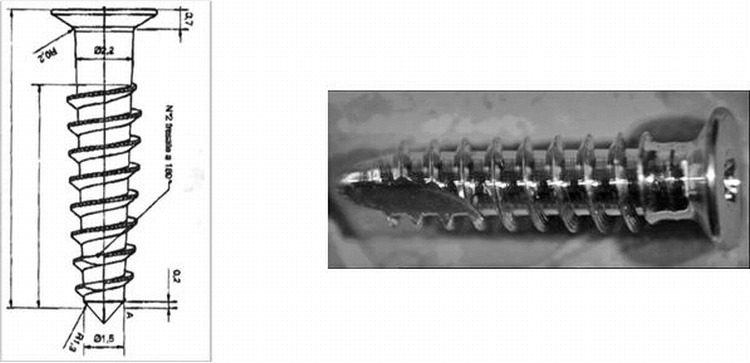
Miniscrew used in the analyses.
The characteristics of this self-threading miniscrew are reported in Table 1 and Figure 1. It consists of an 8-mm threaded part that tapers to a point, a smooth 2.2-mm neck, and a flat 0.8-mm head. In the three-dimensional model, the threads were represented as circular rather than helicoidal for simplicity.
Table 1.
Geometric and Mechanical Properties of the Miniscrew

To model the palate, only a parallel, pipe-shaped region of bone around the screw was considered (the region of interest [ROI]), with its size chosen to render the mechanical effects of the miniscrew negligible outside the ROI. The bone was made up of two different materials, namely cortical and trabecular bone. As previously mentioned, two configurations corresponding to two different sites were constructed. The first, Configuration 1, represented an anterior portion of the palate (about 4 mm from the incisive foramen) made up of a layer of trabecular bone underlying a layer of cortical bone (Figure 2A). The second, Configuration 2, featured a layer of trabecular bone between two cortical layers and represented the thinner posterior portion of the palate (Figure 2B).
Figure 2.
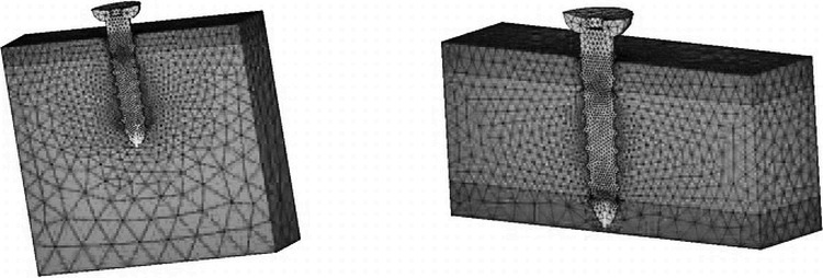
Geometric models and grids of the cases analyzed. (A) Screw inserted into trabecular bone (Configuration 1). (B) Screw inserted into the second layer of cortical bone (Configuration 2). Only half the system is represented for symmetric reasons.
The principal characteristics of the two configurations are reported in Table 2. The dimensions of the different components of the palatal bone were deduced from studies of palatal bone thickness carried out by cone-beam computed tomography.5
Table 2.
Geometric Characteristics and Mechanical Properties of the Bone in Configurations 1 and 2

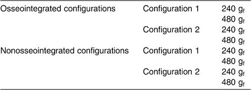
With ANSYS Multiphysics 10.0, the two miniscrew–palatal bone configurations were considered in both a state of total osseointegration between screw and bone and in a state of no osseointegration. In both cases, for each configuration, calculations were made with two different forces applied to the screw: 240 gf (2.35 N) and 480 gf (4.71 N). These load values corresponded to those generated by the application of an orthodontic appliance to the miniscrews. The eight situations are schematically represented in Table 3.
Table 3.
Summary of the Miniscrew–Palatal Bone Systems Examined
The geometric model described previously was rendered into discrete elements using 10-node nonlinear tetrahedral elements (SOLID92), resulting in approximately 75,000 nodes. In this operation, the symmetry of the problem was considered, and thus only half of the domain was actually distinguished and analyzed. The mesh at the interface between the bone and screw was refined to increase the accuracy of the results in this area.
In the nonosseointegrated situations, auxiliary “friction” elements (CONTA170 and TARGE174) were used in the contact surfaces between miniscrew and bone. All materials were considered linearly elastic and isotropic; the mechanical properties (Young's modulus and Poisson's ratio) are reported in Tables 1 through 3. The external surfaces of the modeled bone, except for that at the site of miniscrew insertion, were considered fixed because they form part of the palate and are thus not subject to movement. Furthermore, the load employed to simulate the actual state of tension was applied as a concentrated force applied at one point of the neck of the screws (Figure 3).
Figure 3.
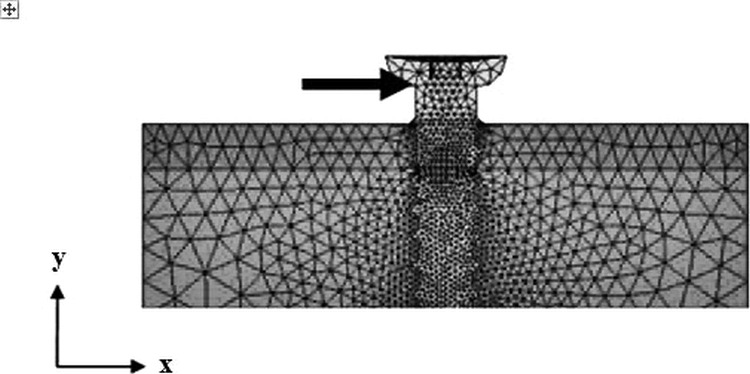
Application of load to the model.
RESULTS
First, the configurations with complete osseointegration were analyzed, and then those with no osseointegration were analyzed. The results of both analyses were subsequently compared to determine the advantages and disadvantages of each.
The two levels of load, 240 gf and 480 gf, were studied. The results of the FEM allowed evaluations of the stress and strain distribution on compact and trabecular bone because of the external loading setup that was simulated. It is important to assess the state of tension to which bone is subjected and, consequently, whether such loading conditions can be considered sufficiently safe for the tissues.
To this end, the authors considered that the normal stress σx and strain εx acted in the same direction as the force applied (ie, the x direction). To identify the areas of potential fracture, the von Mises stress (σVM) was chosen, as this quantity is often used in orthodontics to determine whether a material is able to withstand a certain type of loading and is sometimes directly comparable with the strength of the material in cases of generalized loading.
Osseointegrated Configurations
The results of the simulations of the osseointegrated configurations at each level of load were qualitatively analogous. Therefore, only the configurations loaded with 480 gf are represented in Figures 4 and 5.
Figure 4.
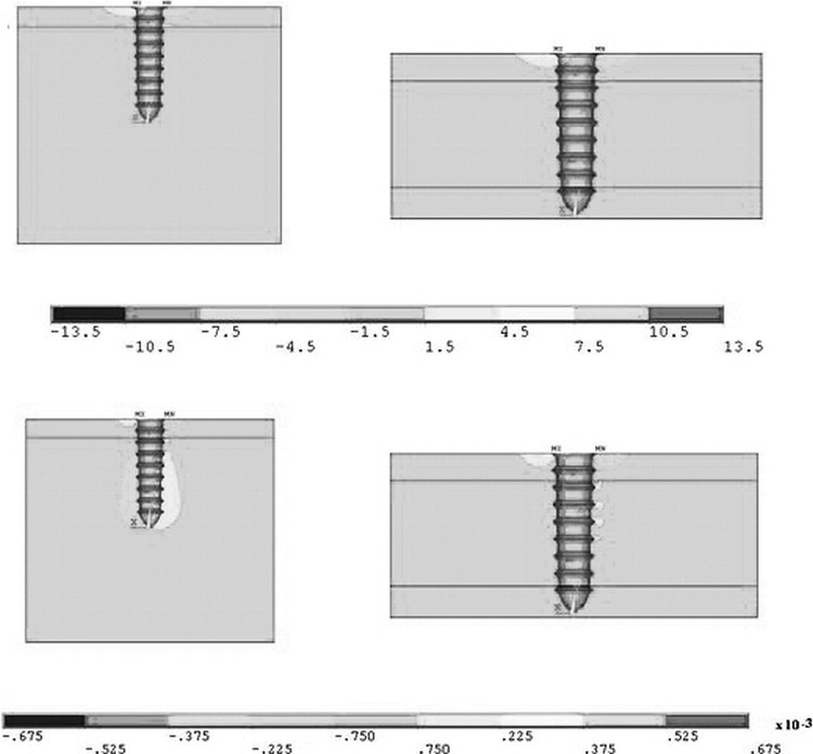
Stress σx in MPa (above) and strain εx (below) for the completely osseointegrated configurations loaded with 480 gf.
Figure 5.
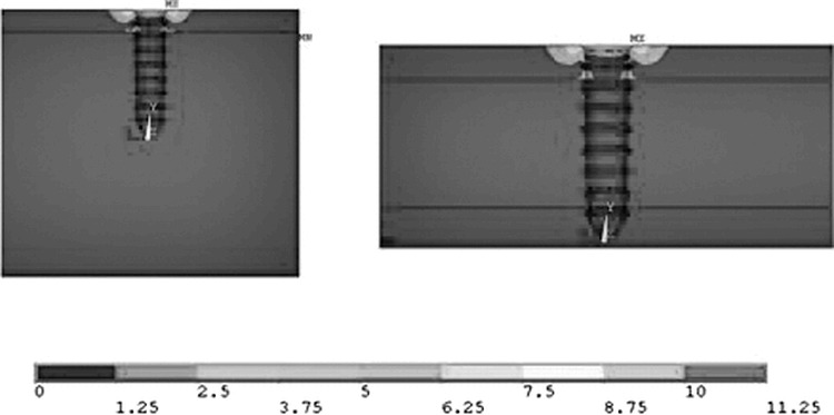
Von Mises stress (MPa) on osseointegrated miniscrews subjected to a load of 480 gf.
Figure 4 reports the σx and εx contour plots and compares the model with one cortical layer to that with two layers. In both cases the stress was distributed in the same fashion (Figure 4A,B), with its maximum value (both in compression and in tension) at about the same magnitude (approximately 11 MPa). In contrast, the resulting strain differed between the two configurations. The strain when only one layer of cortical bone was involved was most apparent in the underlying trabecular layer (Figure 4C). In particular, on the right side of the screw it appeared to be a tensile strain, while on the left of the screw it was compressive, in agreement with physical intuition.
On the other hand, when both cortical layers were involved, the same qualitative result occurred, but it affected a much smaller region in the vicinity of the screw (Figure 4D). This effect was caused by the greater degree of anchorage obtained when the screw was inserted into the second cortical layer, which is stiffer than the trabecular bone and thus able to limit the tipping of the screw.
Consideration of the von Mises stresses (Figure 5A,B) again highlighted the similarity between the two configurations. In both cases the maximum values were approximately 10 MPa in proximity to the external surface of bone, and the areas affected were the same. Moreover, a small area at the interface between the cortical and trabecular layers was subjected to a von Mises stress of around 2 MPa in both configurations.
Configurations Without Osseointegration
In the simulations without osseointegration, the measurements were carried out as per the osseointegrated simulations, and the results for both load values are reported here.
240-gf load
A change in σx distribution was seen in both configurations (Figure 6A,B). In fact, the miniscrews that were inserted into one cortical layer generated a compression σx of approximately 14 MPa at its tip, which may deform the less rigid trabecular bone. However, when the second cortical layer was involved, the tip of the miniscrew generated much lower compressive forces of approximately 2 MPa.
Figure 6.
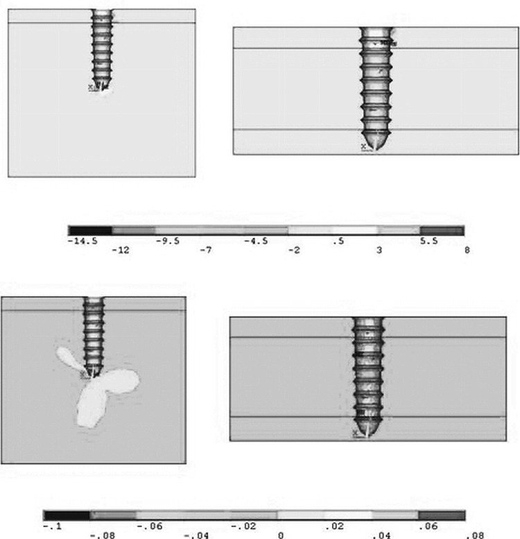
Stress σx in MPa (above) and strain εx (below) for the nonosseointegrated configurations loaded with 240 gf.
The same was also observed for εx. The trabecular zone in the first configuration was deformed by nearly 2%, a situation that did not occur in the second configuration because of the involvement of the second cortical layer.
Calculation of the von Mises stresses (Figure 7A,B) showed a maximum value of approximately 28 MPa in the trabecular bone in the first configuration and a markedly lower figure of approximately 5 MPa in the second configuration, in which the stress was transferred to the two cortical layers.
Figure 7.
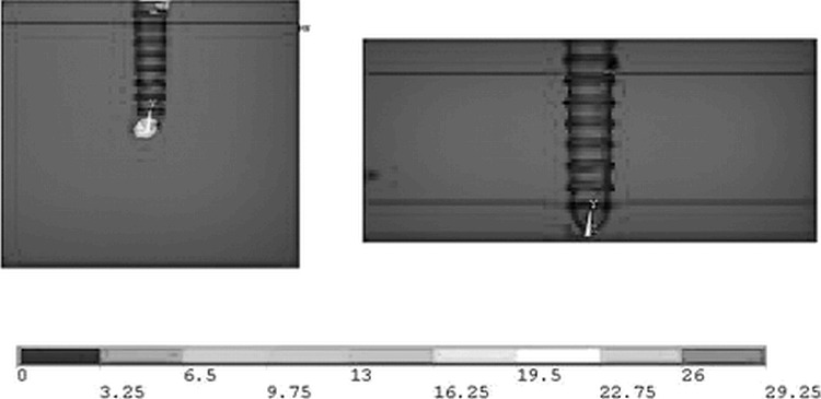
Von Mises stress (MPa) in nonosseointegrated configurations subjected to a load of 240 gf.
480-gf load
Doubling the load on the system led to significant increases in the forces affecting the materials examined. In the first configuration, σx was shown to be distributed predominantly in the first cortical layer, and the maximum value of approximately 20 MPa was found in the trabecular bone at the tip of the screw. The maximum value in the bicortical configuration was approximately 3 MPa. The change in εx was shown to be analogous to that obtained with a 240-gf load and, likewise, the trabecular bone was found to be greatly deformed in the configuration involving one cortical layer (Figure 8A,B).
Figure 8.
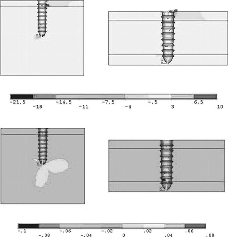
Stress σx in MPa (above) and strain εx (below) for the nonosseointegrated configurations loaded with 480 gf.
Finally, it is interesting to note that the maximum von Mises stress calculated for this situation was approximately 31 MPa, near the tip of the screw in the trabecular region, whereas in the bicortical configuration it was approximately 9 MPa and located in the cortical areas (Figure 9A,B). The maximum values of von Mises stress, used for comparison with the strength of bone in each configuration, and the areas in which they were revealed are reported in Table 4.
Figure 9.
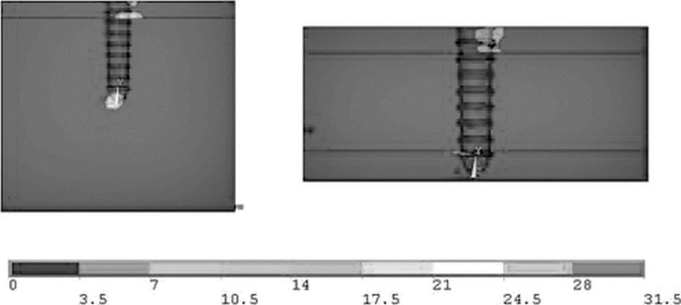
Von Mises stress (MPa) for the nonosseointegrated configurations loaded with 480 gf.
Table 4.
Locations and maximum values of von Mises stress

DISCUSSION
Similar studies of this type of system allow a qualitative comparison of the results. Dalstra et al17 used a miniscrew of similar geometry as that examined here to evaluate the stress distribution in bone, although in their study it was subjected to smaller loads (50 cN, ie, 50 gf). They found that the stress was located predominantly in the cortical bone. Boccaccio et al13 also reached similar conclusions in a two-dimensional FEM study where miniscrews of different lengths were examined (9, 11, and 14 mm) in conditions of varying degrees of osseointegration. Likewise, the FEM simulations in the present study showed that the cortical layer has a determining influence on the state of stress of the miniscrew-bone system. In fact, in all the configurations considered, the presence of a second cortical layer reduces the stress in the trabecular layer, which, being weaker, is the more critical zone.
The results obtained show that, for all the configurations examined, the maximum von Mises stress did not exceed the strength of either the cortical or the trabecular bone. Suitable strength values for palatal trabecular and cortical bone are 50 MPa and 170 MPa, respectively, as reported in a study by Kaplan et al.18 Although these values are averages, and therefore subject to individual variations in bone density, in none of the cases considered in the present study were these critical values exceeded. Therefore, in agreement with Dalstra et al,17 we can say that, in the presence of bone of good quality and adequate thickness, miniscrews do not cause fracture of bone.
In agreement with Boccaccio et al,13 this study showed that osseointegration of the miniscrews resulted in lower stresses on both the trabecular and cortical bone. In addition, the results in the case of no osseointegration, at both load levels, show that the different configurations generated totally different states of stress and strain. In the first configuration, in fact, even though the trabecular region was found to be subject to stress values (31 MPa) that are lower than trabecular bone strength, these are very close to the fracture stress and therefore, considering the subjective variability of this quantity, this situation can be considered to be at risk. However, the insertion of the miniscrews into the second cortical layer improves the situation caused by the resistance to miniscrew tipping provided by this layer. In this configuration the maximum value of the von Mises stress greatly decreases (9 MPa) and is also transferred to the stronger first cortical layer. These results are also confirmed by those obtained by Chen et al19 who, via FEM, compared osseointegrated and nonosseointegrated palatal implants and showed that it is possible to obtain good anchorage under the forces generally applied in orthodontics, even in the absence of osseointegration.
The most interesting aspect of the results obtained in this study is related to the stress distribution in the cases in which the miniscrew contacts both layers of cortical bone in addition to the trabecular bone. When this occurs, in both the presence and absence of osseointegration, the load in both the cortical and trabecular layers is reduced. This is particularly important when larger forces (480 gf) are exerted on nonosseointegrated miniscrews, as this configuration is such that the cortical layers share most of the stress and hence excessive loading of the trabecular bone is prevented.
On the basis of this FEM simulation we can conclude that, from a mechanical point of view, bicortical palatal anchorage is advantageous in clinical practice, especially in the absence of osseointegration, as it reduces the risk of microfractures in the trabecular bone layer. The sole reason for not employing bicortical anchorage in the palate could be the risk of perforation of the nasal cavity floor. However, it has previously been demonstrated that a perforation of the nasal cavity or maxillary sinus of less than 2 mm in diameter heals spontaneously, without complications, and does not compromise primary stability.20,21
CONCLUSIONS
A miniscrew of diameter 2 mm and length 11 mm inserted into the palate is able to withstand loads between 240 and 480 gf, without causing fracture to bone, even in the absence of osseointegration.
Placement of the screw into both cortical layers markedly reduces the load at the trabecular bone and increases the stability of the implant.
REFERENCES
- 1.Lee J. S, Kim D. H, Park Y. C, Kyung S. H, Kim T. K. The efficient use of midpalatal miniscrew implants. Angle Orthod. 2004;74:711–714. doi: 10.1043/0003-3219(2004)074<0711:TEUOMM>2.0.CO;2. [DOI] [PubMed] [Google Scholar]
- 2.Paik C. H, Ahn S. J, Nahm D. S. Correction of Class II deep overbite and dental and skeletal asymmetry with 2 types of palatal miniscrews. Am J Orthod Dentofacial Orthop. 2007;131(4 suppl):S106–116. doi: 10.1016/j.ajodo.2006.02.033. [DOI] [PubMed] [Google Scholar]
- 3.Gracco A, Lombardo L, Cozzani M, Siciliani G. Assessment of palatal bone thickness in adults with cone beam computerized tomography. Aust Orthod J. 2007;23:109–113. [PubMed] [Google Scholar]
- 4.Gracco A, Lombardo L, Siciliani G. Molar distalisation with skeletal anchorage. Aust Orthod J. 2007;23:147–152. [PubMed] [Google Scholar]
- 5.Gracco A, Lombardo L, Cozzani M, Siciliani G. Quantitative cone-beam computed tomography evaluation of palatal bone thickness for orthodontic miniscrew placement. Am J Orthod Dentofacial Orthop. 2008;134:361–369. doi: 10.1016/j.ajodo.2007.01.027. [DOI] [PubMed] [Google Scholar]
- 6.Kyung S. H, Hong S. G, Park Y. C. Distalization of maxillary molars with a midpalatal miniscrew. J Clin Orthod. 2003;37:22–26. [PubMed] [Google Scholar]
- 7.Kinzinger G. S. M, Diedrich P. R, Bowman S. J. Upper molar distalization with a miniscrew-supported distal jet. J Clin Orthod. 2006;15:672–678. [PubMed] [Google Scholar]
- 8.Kircelli B. H, Pektas Z. O, Kircelli C. Maxillary molar distalization with a bone-anchored pendulum appliance. Angle Orthod. 2006;76:650–659. doi: 10.1043/0003-3219(2006)076[0650:MMDWAB]2.0.CO;2. [DOI] [PubMed] [Google Scholar]
- 9.Buchter A, Wiechmann D, Koerdt S, Wiesmann H. P, Piffko J, Meyer U. Load-related implant reaction of mini-implants used for orthodontic anchorage. Clin Oral Implants Res. 2005;16:473–479. doi: 10.1111/j.1600-0501.2005.01149.x. [DOI] [PubMed] [Google Scholar]
- 10.Cope J. B. Temporary anchorage devices in orthodontics: a paradigm shift. Semin Orthod. 2005;11:3–9. [Google Scholar]
- 11.Costa A, Raffaini M, Melsen B. Miniscrews as orthodontic anchorage: a preliminary report. Int J Adult Orthod Orthognath Surg. 1998;13:201–209. [PubMed] [Google Scholar]
- 12.Kanomi R. Mini-implant for orthodontic anchorage. J Clin Orthod. 1997;31:763–767. [PubMed] [Google Scholar]
- 13.Gracco A, Boccaccio A, Cirignaco A, Cozzani M, Pappalettere C, Vitale G. Numerical/experimental analysis of the stress field around miniscrews for the orthodontic anchorage. Eur J Orthod. 2009 Feb;31:12–20. doi: 10.1093/ejo/cjn066. [DOI] [PubMed] [Google Scholar]
- 14.Pegoretti A, Fambri L, Zappini G, Bianchetti M. Finite element analysis of a glass fibre reinforced composite endodontic post. Biomaterials. 2002;23:2667–2688. doi: 10.1016/s0142-9612(01)00407-0. [DOI] [PubMed] [Google Scholar]
- 15.Toparli M, Sasaki S. Finite element analysis of the temperature and thermal stress in a postrestored tooth. J Oral Rehabil. 2003;30:921–926. doi: 10.1046/j.1365-2842.2003.01071.x. [DOI] [PubMed] [Google Scholar]
- 16.Tanaka M, Naito T, Yokota M, Kohno M. Finite element analysis of the possible mechanism of cervical lesion formation by occlusal force. J Oral Rehabil. 2003;30:60–67. doi: 10.1046/j.1365-2842.2003.00959.x. [DOI] [PubMed] [Google Scholar]
- 17.Dalstra M, Cattaneo P, Melsen B. Load transfer of miniscrews for orthodontic anchorage. Orthod. 2004;1:53–62. [Google Scholar]
- 18.Kaplan F. S, Hayes W. C, Keaveny T. M, Boskey A, Einhorn T. A, Iannotti J. P. Form and function of bone. In: Simon S. R, editor. Orthopaedic Basic Science 1st ed. Rosemont, IL: American Academy of Orthopaedic Surgeons; 1994. pp. 127–174. [Google Scholar]
- 19.Chen F, Terada K, Hanada K, Saito I. Anchorage effect of osseointegrated vs nonosseointegrated palatal implants. Angle Orthod. 2006;76:660–665. doi: 10.1043/0003-3219(2006)076[0660:AEOOVN]2.0.CO;2. [DOI] [PubMed] [Google Scholar]
- 20.Brånemark A. M, Adell R, Albrektsson T, Lekholm U, Lindstrom J, Rockler B. An experimental and clinical study of osseointegrated implants penetrating the nasal cavity and maxillary sinus. J Oral Maxillofac Surg. 1984;42:497–505. doi: 10.1016/0278-2391(84)90008-9. [DOI] [PubMed] [Google Scholar]
- 21.Kang S, Lee S. J, Ahn S. J, Heo M. S, Kim T. W. Bone thickness of the palate for orthodontic mini-implant anchorage in adults. Am J Orthod Dentofacial Orthop. 2007;131:S74–81. doi: 10.1016/j.ajodo.2005.09.029. [DOI] [PubMed] [Google Scholar]


