Abstract
In response to the global outbreak of the coronavirus pandemic (COVID-19), a staggering amount of personal protective equipment, such as disposable face masks, has been used, leading to the urgent environmental issue. This study evaluates the feasibility of mask chips for the soil reinforcement, through triaxial tests on samples mixed with complete decomposed granite (CDG) and mask chips (0%, 0.3%, 0.5%, 1%, 5% by volume). The experimental results show that adding a moderate volumetric amount of mask chips (0.3%–1%) improves the soil strength, especially under high confining pressure. The optimum volumetric content of mask chips obtained by this study is 0.5%, raising the peak shear strength up to 22.3% under the confining stress of 120 kPa. When the volumetric content of mask chips exceeds the optimum value, the peak shear strength decreases accordingly. A limited amount of mask chips also increases the elastic modulus and makes the volumetric response more dilative. By contrast, excessive mask chips create additional voids and shift the strong soil-mask contacts to weak mask-mask contacts. The laser scanning microscope (LSM) and scanning electron microscope (SEM) images on the typical samples demonstrate the microstructure of mask fibers interlocking with soil particles, highly supporting the macro-scale mechanical behavior.
Keywords: COVID-19, Face masks, Reinforced soil, Triaxial test, Microstructure
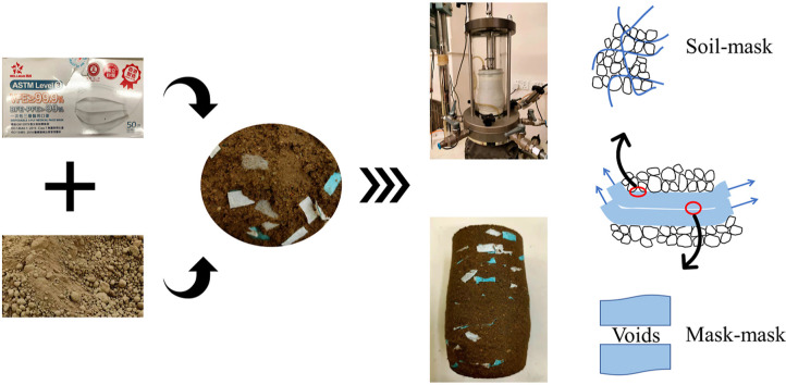
Graphical abstract
1. Introduction
During the coronavirus pandemic (COVID-19), tons of disposable face masks have been utilized to protect people from getting infected. As the pandemic still exists in many countries or regions worldwide, wearing face masks will be a daily routine in the near future. The recycling and reuse of disposable face masks are considerably challenging to the world (Vaverková et al., 2021). Even worse, unreasonable treatment may also lead to secondary pollution and even the spread of the virus, posing huge health hazards (Tian et al., 2020). Conventional waste treatment methods for the wasted face masks include incineration and landfill, while both methods have shortcomings. Energy consumption and carbon generation in the incineration process have always been the concern, which is beyond the policy of carbon neutralization supported by many countries. At the same time, polypropylene (PP), which is the main plastic component for masks, has been reported to take hundreds of years to degrade in landfills. Therefore, it is urgent and meaningful to propose a green and practical approach to treat wasted face masks.
Research has shown that masks can be self-sterilized under sunlight illumination without damage, offering the possibility of recycling masks in civil and construction engineering, which has been proposed recently (Zhong et al., 2020). Saberian et al. (2021) added shredded face masks into the recycled concrete aggregate (RCA), stating that masks could improve RCA strength within 2% mass content. Rehman and Khalid (2021) used face masks and silica fume to form a composite binary mixture to stabilize fat clay, claiming that the mixture was effective in improving strength and regulating the ductility of clay. Although the previous studies have displayed the potential application of face masks used in construction projects, a refined design basis is still needed with an in-depth investigation. For example, the experimental tests conducted previously were mainly unconfined compression tests, which failed to mimic triaxial stress state in practical field conditions. Furthermore, the host materials were focused on concrete or aggregates by far, whereas soil, as the most common construction material for infrastructures, has not received enough attention. Motivated by the current global situation, an innovative and energy-efficient treatment method is imperative, to use mask chips for soil reinforcement. Zhang et al. (2022) applied mask chips to reinforce well-graded lime-stone, concluding that the mixture of mask chips with granular soil increased shear strength, reduced shear-induced volumetric dilation and stiffness in the studied range. This study proposed an innovative method to recycle the disposable face mask, which could simultaneously solve energy consumption and land occupation problems compared with traditional treatment methods in the post-COVID-19 era. However, this study focused on the granular material. Hence, the effect of mask chips on the mechanical behavior of the cohesive soil was still unknown.
Soil reinforcement techniques with fibers have been extensively studied and well-developed (Dos Santos et al., 2010; Li et al., 2019, Li et al., 2019; Tang et al., 2012; Yang et al., 2017; Chen et al., 2021). As listed in Table 1 , the most common fibers adopted in reinforcement are commercial polypropylene fibers owing to their high strength, light weight, good elasticity, and excellent dispersibility (Ajayi et al., 2017; Liu et al., 2018; Madhusudhan et al., 2017; Mirzababaei et al., 2018; Wang et al., 2020). Other synthetic (e.g., asphalt, glass, rubber, carbon fibers) and natural fibers (e.g., coir, banana, and oil palm empty fruit bunch fibers) have also been utilized as sand/clay reinforcement material. (Ahmad et al., 2010; Mittal and Gill, 2018; Namjoo et al., 2019; Patel and Singh, 2019; Sridhar and Prathap Kumar, 2018; Xiao et al., 2019). Regarding the fiber-reinforced soil, fibers behave as tension-resisting elements in soil, thus improving soil peak strength and limiting the post-peak shear resistance losses (Mandolini et al., 2019; Wang and Brennan, 2019). However, the addition of fibers does not guarantee positive effects because the shear strength of the reinforced soil decreased when the fiber content exceeded a certain threshold (Mohamed, 2012). Extensive studies explained that the reinforcement efficiency was dependent on many aspects: the fiber properties (e.g., type, surface roughness, content, length, aspect ratio), soil properties (e.g., particle size distribution, cohesion), and spatial configuration (e.g., fiber orientation and packing method) (Cai et al., 2006; Diambra and Ibraim, 2015; Li et al., 2020). Although numerous investigations have been reported on the mechanical behaviors of the fiber-reinforced soils, the face masks encompass quite different properties compared to the conventional and widely-used synthetic polypropylene fibers in terms of shape, size, tensile stiffness and strength, etc. Thus, the mechanical performance of soil reinforced by mask chips needs to be investigated by experimental tests before the practical application of mask chips used for soil reinforcement.
Table 1.
Investigation on the mechanical behavior of fiber-reinforced soil.
| Fiber Type | Fiber Tensile Strength | Host Material | Reinforcement effect | Reference | |
|---|---|---|---|---|---|
| Synthetic Fibers | Polypropylene fibers | 120 MPa | Clay | The inclusion of fibers increasing peak and residual shear strength, unconfined compressive strength, and the optimum fiber content around 0.4–0.8% of the weight | Pradhan et al. (2012) |
| Polypropylene fibers | 350 MPa | Clayey soil | Improvement in soil resistance and the brittleness index | Plé and Lê (2012) | |
| Short discrete polypropylene fiber | 350 MPa | Clay | Significantly increasing soil tensile strength and soil tensile failure ductility | Li et al. (2014) | |
| Basalt fibers | 3200 MPa | Biocemneted silica sand | The sand unconfined compressive strength, splitting tensile strength, and peak failure state strain rising with increasing fiber content | Xiao et al. (2019) | |
| Glass fibers | 1700 MPa/3500 MPa | Lean clay | Fibers improving the unconfined compressive strength and the optimum glass fiber content at 0.75% | Sujatha et al. (2021) | |
| Carbon fibers | 3500 MPa | Biocemneted silica sand | Unconfined compressive strength increasing with fiber content | Lv et al. (2021) | |
| Natural fibers | Oil palm empty fruit bunch fibers (OPEFB) | 283 MPa | Silty sand | OPEFB significantly improving the shear strength of silty sand | Ahmad et al. (2010) |
| Coir fibers | NAa | Sand | Cyclic stiffness of sand increasing with the content of coir fibers | (Sridhar and Prathap Kumar, 2018) | |
| Banana fibers | NAa | Gravelly sand stabilized with sodium silicate | The plasticity index, unconfined compressive strength, shear strength, splitting tensile strength increasing with the banana fiber content. | Gobinath et al. (2020) | |
NA: Not applicable.
To evaluate the feasibility of applying the disposable mask for soil reinforcement, the mechanical behavior of the soil-mask chip mixture is examined in the present study. The sample was prepared, using complete decomposed granite (CDG) mixed with mask chips (0%, 0.3%, 0.5%, 1%, 5% by volume). A series of triaxial tests was conducted, focusing on the stress-strain behavior of the reinforced soil, with five different volumetric contents of mask chips. The mechanical parameters, including elastic modulus, Poisson's ratio, and dilatancy angle were analyzed. The cohesion and friction angle at peak state were identified based on the critical state line. Furthermore, the laser scanning microscope (LSM) and scanning electron microscope (SEM) were employed to analyze the microstructure of the samples and shed light on the mask reinforcement mechanism.
2. Materials and methods
2.1. Tested soil
Complete decomposed granite (CDG) used in this study is a residual soil with particles made mostly of quartz and feldspar, widely distributed in Hong Kong (Miranda Pino and Baudet, 2015). The chemical composition of CDG is obtained by X-ray fluorescence (XRF) analysis and listed in Table 2 . The in-situ CDG soil was firstly grinded to soil particles smaller than 2 mm, with the grain size distribution shown in Fig. 1 . The specific gravity (G s) of CDG particles is measured as 2.59, with the plastic limit (PL) of 15.28 and the liquid limit (LL) of 33.45, classifying the material as lean clay (CL) (ASTM, 2017). The standard proctor compaction test was conducted for the CDG soil according to ASTM D698-12 (ASTM, 2012). The result is shown in Fig. 2 , defining an optimum water content w opt equal to 14.5% and a maximum dry density ρ dmax equal to 1.83 Mg/m3.
Table 2.
XRF test result for the testing CDG soil.
| Component | SiO2 | Al2O3 | Fe2O3 | K2O | TiO2 | MnO | CaO | PbO | SrO | Rb2O |
|---|---|---|---|---|---|---|---|---|---|---|
| Mass content (%) | 61.12 | 30.19 | 4.23 | 2.73 | 0.91 | 0.47 | 0.17 | 0.09 | 0.02 | 0.01 |
Fig. 1.
Grain size distribution curves of CDG.
Fig. 2.
Standard proctor compaction curve of CDG.
2.2. Adopted disposable face mask
The clean face mask is utilized in this study, since the used face mask is currently not allowed in the laboratory for safety reasons. The clean mask is the disposable medical face mask produced by Ever Sharp Mask (China) Limited. The top and bottom layers of the mask are made of non-woven fabric, while the middle layer is the polypropylene meltblown filter. The basic physical properties of the mask are listed in Table 3 . The specific gravity and tensile properties of masks are determined according to ASTM D792-08 (ASTM, 2008) and ASTM D5035-06 (ASTM, 2006), respectively. The water absorption of 24 h is obtained following the ASTM D570-98 (ASTM, 2018). As the flow chart and the photograph in Fig. 3 shows, the metal trips and earloops were removed before masks were cut into chips manually, which shared the same length of 10 mm and width of 5 mm, and the average thickness of the mask was 0.5 mm. The aspect ratio (λ) with the rectangular cross-section is defined as (Saberian et al., 2021):
| (1) |
where l is the length of the mask chips (10 mm); d FIER is the equivalent diameter; a and b are the width (5 mm) and the thickness (0.5 mm) of the cross-section of the mask chips, respectively. Thus, the aspect ratio λ can be calculated as 11.87. A parameter, namely the volumetric content of mask chips, is introduced as f v modified from Wang et al. (2017, 2018a, 2018b), representing the volume percentage of the mask chips in the whole specimen f v as:
| (2) |
where V mask is the volume of mask chips, calculated through dividing the mass of mask chips by the density; and V total can be calculated according to the specimen size, which has a diameter of 50 mm and a height of 100 mm in this study.
Table 3.
Basic physical and mechanical properties of face mask.
| Specific gravity, Gs | 0.11 |
|---|---|
| Aspect ratio, λ | 11.87 |
| Breaking tensile strength (MPa) | 2.86 |
| Stiffness at strain of 2% (kN/m) | 10.74 |
| Elongation at break (%) | 20.88 |
| Water absorption 24 h (%) | 6.07 |
Fig. 3.
Flow chart and photograph of the mask chips preparation.
2.3. Testing plan
Five groups of samples were prepared, with different f v values for mask chips (0%, 0.3%, 0.5%, 1%, 5%). The parameters for each group of sample are listed in Table 4 . For sample preparation, water was first added and mixed with CDG of pre-determined mass to achieve the optimal water content and 95% compaction degree, which is a widely-used compaction parameter for subgrade or infrastructure constructions (Chen et al., 2019). After mixing, the soil was stored in a sealed container for 24 h for moisture homogenization. Then, the soil was mixed with the dry mask chips with the pre-determined mass and the mixture was compacted in a mold by three layers to achieve 50 mm diameter and 100 mm height. The mixing was conducted using a scoop manually, and visual inspection helped ensure the mask chips distribute randomly and uniformly in the CDG soil. From the photos of the surface or cross-section of the sample after the testing, it can be visually observed that the mask chips are distributed relatively uniformly in the samples (as shown in Fig. 4, Fig. 5 ). In addition, more compaction layers can ensure a better uniformity. From the previous studies (Wang et al., 2017, 2018a; 2018b), three layers’ compaction can guarantee that the sample is uniformly prepared with two mixtures. Note that although different f v values were controlled for each group of sample, the optimum water content and the 95% compaction degree of the pure CDG soil were kept the same, as for the definition of f v (Wang et al., 2017, 2018a; 2018b). The mass of CDG and mask chips were also determined based on the definition of f v. As the mask chips have been dried in the oven, it could be assumed that the mask did not contain water, while air and water existed in the CDG soil. For example, the volume content of the mask chips is 0.3%, and the volume content of the CDG is 99.7%. The volume of the sample (50 mm diameter and 100 mm height) is 196.34 cm3. Thus, the volume of the mask chips and CDG is 0.59 cm3 (=0.3%*Vsample) and 195.7 cm3 (=99.7%*Vsample), respectively. The density of mask chips and CDG is 0.11 g/cm3 and 1.74 g/cm3 (95% ρdmax). Then, the mass of mask chips and CDG could be determined as 0.06 g (=0.11*0.59) and 340.33 g (=1.74*195.7), as listed in Table 4, row 3. After sample preparation, triaxial tests were conducted with the drainage valve open. The axial loading rate was set as 0.1 mm/min. For each group, different confining pressures, including 30, 60, and 120 kPa, were adopted in the tests. The tests ended when the axial strain of the specimen reached 18%, where the deviator stress was considered stable. Furthermore, in order to investigate the reinforcement mechanism of mask chips on the CDG, the laser scanning microscope (LSM) and scanning electron microscope (SEM) were employed to analyze the microstructure of the selected samples.
Table 4.
List and properties of the samples.
| Name | fv (%) | w (%) | ρ (g/cm3) | ms-CDG (g) | ms-MC (g) |
|---|---|---|---|---|---|
| I | 0 | 14.5 | 1.74 | 341.40 | 0 |
| II | 0.3 | 14.5 | 1.74 | 340.33 | 0.06 |
| III | 0.5 | 14.5 | 1.74 | 339.65 | 0.11 |
| IV | 1 | 14.5 | 1.74 | 337.94 | 0.22 |
| V | 5 | 14.5 | 1.74 | 324.29 | 1.08 |
Fig. 4.
View of selected soil samples after shearing (stress in the figure represents the confining pressure).
Fig. 5.
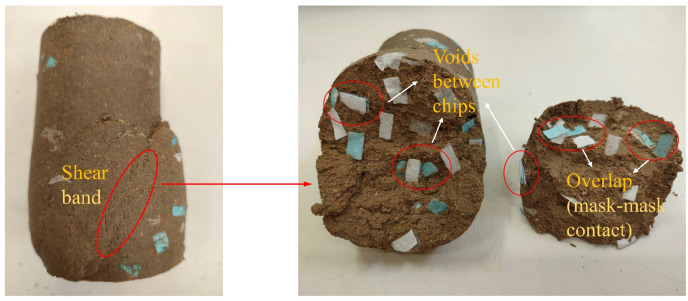
Visual view of shear band (fv = 5% under 60 kPa).
3. Results and discussions
3.1. Stress-strain behavior
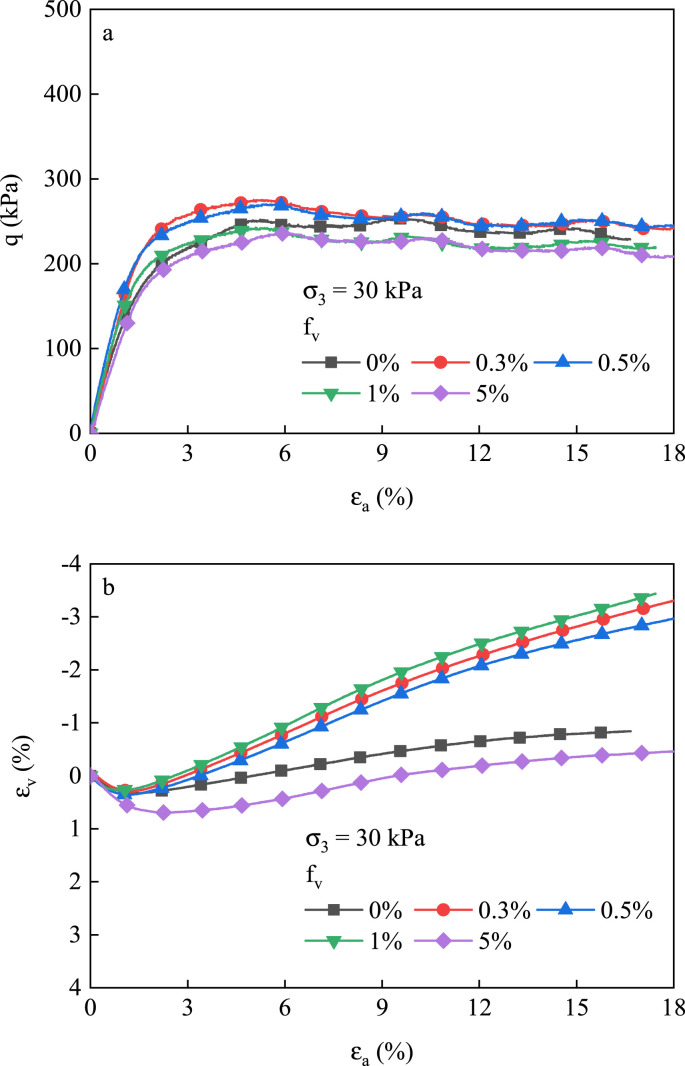
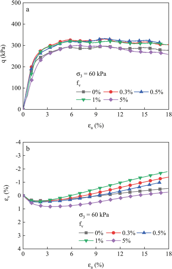
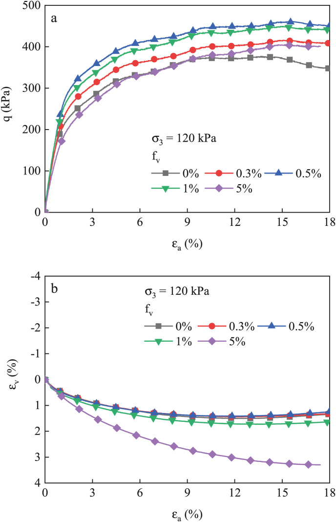
Fig. 4 shows three typical samples with different mask contents after shearing under various confining pressures, and Fig. 5 offers a close view of the shear band. As the mask content increases, more mask chips could be observed on the sample surface, particularly on the sample at 5%, where the overlapping of mask chips and the cracks induced by chips voids could be clearly observed both on the surface and shear band. Fig. 6, Fig. 7, Fig. 8 present the stress-strain behavior of samples under different confining pressure, where q is the deviator stress, ε a is the axial strain, and ε v is the volumetric strain. In this study, the negative volumetric strain indicates dilation, and the positive value stands for contraction. Generally, the deviator stress increases against the axial strain, followed by a stable variation trend with the continuous increase of the axial strain. For a given confining pressure, the curves of the samples with f v = 0.3%–1% are higher than those with f v = 0% or 5%. This difference is more distinct when the confining pressure is higher. For the relationship between the volumetric strain and the axial strain, the dilation only emerges following contraction when the confining pressure is 30 kPa or 60 kPa. By contrast, under 120 kPa confining pressure, dilation is not observed for all the samples.
Fig. 6.
Stress-strain curves of all samples at σ3 = 30 kPa.
Fig. 7.
Stress-strain curves of all samples at σ3 = 60 kPa.
Fig. 8.
Stress-strain curves of all samples at σ3 = 120 kPa.
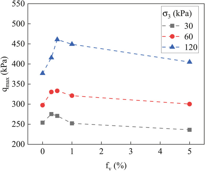
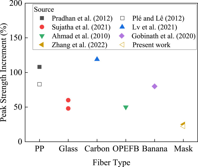
The variations of the peak deviator stress with f v are summarized in Fig. 9 for a more straightforward presentation, with a non-monotonic relationship. In short, the addition of low content of mask chips (lower than 0.5%) significantly raises the peak deviator stress, achieving the reinforcement effect. When f v is 0.5%, the maximum deviator stress is 270.7 kPa, 333.1 kPa and 460.8 kPa, whose increment compared to the control sample (f v = 0%) reaches 6.6%, 12.0%, and 22.3% under 30 kPa, 60 kPa, and 120 kPa confining pressure, respectively. However, as the mask content surpasses 0.5%, the peak deviator stress declines, even getting closer to that of pure CDG. Thus, 0.5% content by volume is reasonable to be considered as the optimum dose in this case. The non-monotonic trend is also consistent with the previous studies on fiber-reinforced soil. Pradhan et al. (2012) included randomly distributed polypropylene fibers in the cohesive soil and reported optimum content of fibers was 0.4–0.8% (by weight) for fiber aspect ratio of 100, as it produced the highest peak and residual strength obtained by direct shear tests. The same trend was also observed by Lv et al. (2021), as the unconfined compressive strength of polypropylene fiber-reinforced bio-cemented sand reached the maximum when the volume percentage of fiber was 0.2% and then decreased. Fig. 10 summarizes different fiber reinforcement effects from previous studies and present work. The peak strength increment was chosen to evaluate the reinforcement effect, which was the percentage of the maximum peak strength increment of the reinforced soil at the studied range compared with pure soil. For example, the peak deviator stress increment of mask chips at f v = 0.5% with σ3 = 120 kPa in this study was chosen. It should be emphasized that for the experiments cited here, the adopted soil properties (biocemented sand or clay) and the experimental methods (UCS, direct shear and triaxial test) were different from case to case due to the various sources, and the maximum peak strength increment was chosen as a measure here just to make an intuitive comparison. More details could be found in Table 1. Generally, the widely-used synthetic or natural fibers succeeded the studied mask chips, which could be attributed to the better tensile properties or more rational geometry of these fibers. The difference between various host soil and test methods could also contribute to the difference of the reinforcement effect as well as the optimum dose values from this study and other research. Therefore, even though the reinforcement effect of the mask chips seemed not as ideal as conventional ones, the comparison revealed the positive effect of mask chips and the potential to be improved after further clarification.
Fig. 9.
Variations of peak deviator stress with fv.
Fig. 10.
Comparison of peak strength increment with previous studies on different fiber reinforced soil.
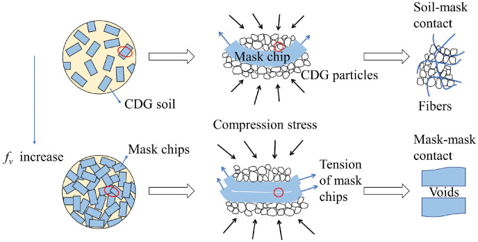
The principle of conventional fiber reinforcement could explain the increase of shear strength of the samples at a relatively low f v, related to the tension-resisting role of fibers in the soil. The interfacial force between the fibers and soil particles restricts the relative sliding of the fibers so that the fibers can withstand a certain amount of tensile stress, thus playing a role in sharing the external load. In addition, when the fibers are in a tension state, there is a restraining effect on the soil particles near the bending part of the fibers, which could limit the soil particle deformation and help improve the mechanical properties. However, the excessive addition of mask chips creates larger voids and results in fibers balling, which obstructs the loading transfers and reduces the strength (Saberian et al., 2021). As mentioned before, the visual view of the samples with 5% mask chips (Fig. 4, Fig. 5) also exhibits that the mask chips overlap and are stuck together due to poor mixing, which inevitably causes low-density cracks in the specimen. Furthermore, the soil-mask contacts have been gradually replaced by mask-mask contacts, as Fig. 5 shows, which are much weaker than the previous ones due to the significantly smaller roughness of the mask surface.
3.2. Elastic modulus
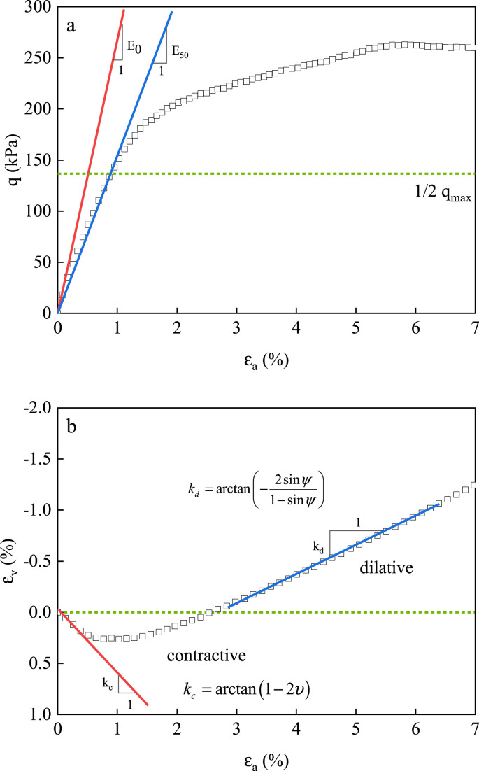
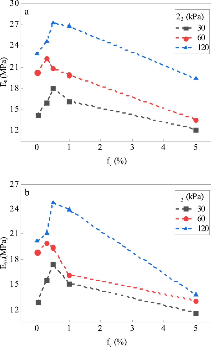
Fig. 11(a) illustrates the determinations of the elastic modulus E0 and the secant modulus E50. E0 is the tangent modulus at the initial elastic stage, determined by the ratio of deviator stress to the axial strain within the range of 0%–0.1% in this research. E50 is the secant modulus at 50% peak deviator stress (q50). Fig. 12 depicts the variations of elastic modulus and secant modulus with f v. The variation trends of E0 and E50 with f v are similar, generally consistent with peak deviator stress changes in Fig. 9. At a given f v, higher confining pressure leads to a greater elastic modulus or secant modulus. For different confining pressures, samples at 0.3% (60 kPa) or 0.5% (30 kPa and 120 kPa) witness the peak modulus, approximately 20%–35% higher than the control sample (f v = 0%). The lowest elastic modulus is obtained using 5% mask chips, showing a 15%–35% drop compared to pure CDG for both E0 and E50. It can be assumed that adding a moderate amount of mask chips, such as 0.3%–0.5% by volume, improves the integrity of the mixture. Still, too many chips generate a loss of sample stiffness due to the high amount of voids.
Fig. 11.
Determination of (a) elastic modulus E0, secant modulus at 50% peak deviator stress E50, (b) Poisson's ratio ν, and dilatancy angle ψ
Fig. 12.
Variations of elastic modulus (a) E0 and (b) E50 with fv.
3.3. Poisson's ratio and dilatancy angle
The volumetric strain to axial strain relationship determines Poisson's ratio ν and dilatancy angle ψ. These two parameters are defined as (Fig. 11(b); Yin et al. (2020):
| (3) |
| (4) |
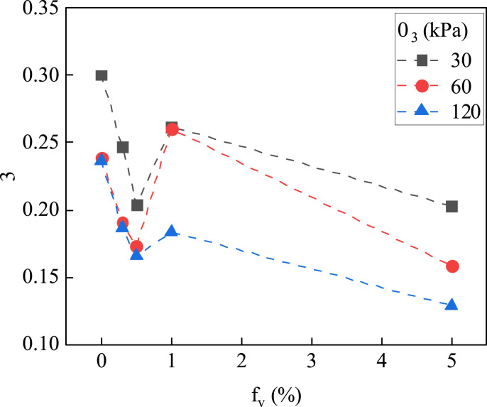
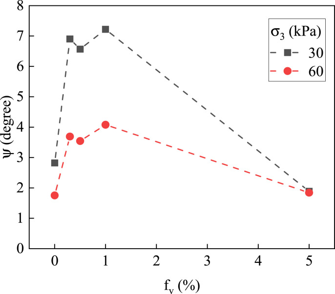
where k c is the slope of the ε v-ε a curve at the contractive phase; k d is its counterpart in the dilative phase. Fig. 13, Fig. 14 display the variation of Poisson's ratio and dilatancy angle with f v, respectively.
Fig. 13.
Variations of Poisson's ν ratio with fv.
Fig. 14.
Variations of dilatancy angle ψ with fv.
It can be observed from Fig. 13 that Poisson's ratio varies between 0.15 and 0.3. Generally, at a given f v, Poisson's ratio declines when the confining pressure rises from 30 kPa to 120 kPa. The pure CDG samples produce the highest Poisson's ratio. In the studied range, the variations of Poisson's ratio against the volumetric content of the mask chips are non-monotonic. The research presenting the relationship between the Poisson's ratio and the fiber inclusions is limited, and no apparent relationship has been reported between the Poisson's ratio and fiber content.
The dilatancy angle obtained in this study ranges from 1.5 to 7°, while samples without dilatative behavior are not shown in Fig. 14. It is evident that the lower confining pressure favors dilatancy, as the dilatancy angle under 30 kPa is greater than that of the sample at the same f v under 60 kPa. However, there is no dilatative observation for all the samples under 120 kPa (see Fig. 6, Fig. 7, Fig. 8). In terms of mask content, the dilatancy angle increases to a maximum value at a small f v (1%) and then decreases. The dilatancy angle variation trend agrees with the peak deviator stress, indicating a relationship between the increase of shear strength and dilation. Previous investigations on fiber-reinforced sand or clay have also concluded that fiber inclusion results in a more dilative volumetric response (Diambra et al., 2010; Eldesouky et al., 2016; Ibraim and Fourmont, 2007; Kong et al., 2019, Muir Muir Wood et al., 2016). However, it is worth noting that not all present research reports increased dilatancy with fiber existence, especially under high confining pressure and in the dense sample using direct shear or triaxial test (Heineck Heineck Karla et al., 2005). The apparent contradiction may be caused by many factors, such as the properties of the soil (type, particle size, relative density, etc.) and fibers (length, aspect ratio, etc.) used in the experiments as well as the experimental condition (experimental methods, confining pressure, etc.) (Ghadr, 2020; Sadek et al., 2010). According to Falorca and Pinto (2011), dilatancy seemed to be due to the enlargement of the shear zone. In their direct shear test, soil particles deformed, leading to the pullout of fibers and empty space developing in the shear box. Thus, a larger shear zone was observed in the reinforced sample as well as the more pronounced dilation behavior than the unreinforced one. However, this hypothesis may not be able to explain the results in this study, as significant shear zone enlargement was not observed at 1% in visual inspections after shearing. More studies are needed to provide a convincing explanation of the dilatancy of CDG with mask chips.
3.4. Cohesion and friction angle
The internal friction angle and cohesion for the unsaturated soil at peak state can be defined as:
| (5) |
| (6) |
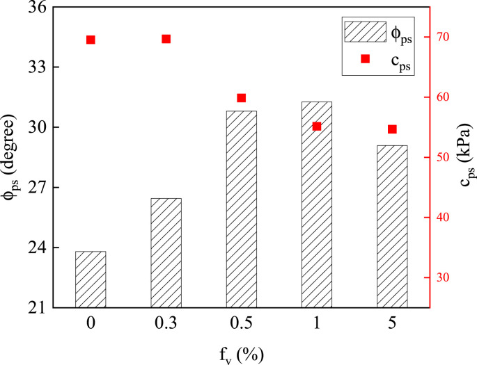
where M and S are the slope and intercept of the critical state line in the p-q plane, respectively; p is the mean total stress. Fig. 15 shows the variations of the internal friction angle and the cohesion at peak state with f v. It can be observed that the cohesion at peak state ranges from 50 kPa to 70 kPa. It decreases when f v increases, suggesting that higher mask content leads to weaker cohesion between soil particles. This is because cohesion is only contributed by CDG particle. Hence, the replacement of soil particles by mask chips results in a lower cohesion. The internal friction angle rises in the beginning and then decreases with the increase of f v. Compared to the pure CDG sample, the internal friction angle is always larger at the f v range smaller than 5%. The increase of internal friction angle can be related to the fact that most of the fibers on the shear surface are not arranged parallel to the shear direction, which is conducive to enhancing the friction between soil particles and mask chips (Wang et al., 2013). By contrast, one possible reason for the decrease of the internal friction angle at 5% is that the replacement of soil particles by mask chips on the shear surface gives rise to weak mask-mask contacts. Another explanation may be that the formation of local fiber clusters obstructs the bonding between fibers and soil (Yang et al., 2011). Given that the fiber-reinforced soil is a complex composite material, the mechanical properties of the fiber-soil interface have not been fully unraveled by the present study, which needs to be further investigated.
Fig. 15.
Variations of internal friction angle and cohesion with fv at peak state.
3.5. Microstructures and reinforcement mechanism
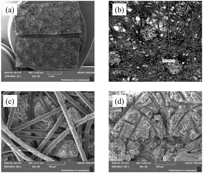
The microstructure of the samples was investigated by LSM and SEM techniques to provide microscopic insight into the reinforcement mechanism. LSM scans were performed using clean mask chips, and SEM scans were conducted using clean mask chips and the sample at f v = 5% after shearing under 120 kPa. It is noted that the sample size for SEM observation is tiny, and to ensure that suitably sized soil fragments with and without mask chips could be taken from the shear surface simultaneously, the sample with the highest mask content (5%) was selected. Fig. 16 shows the structure of both mask chips and soil-mask mixtures at the micron scale. The randomly-oriented fiber network structure of the non-woven fabric is shown in Fig. 16(a) and (b). As can be seen from Fig. 16(a), a small mask chip contains numerous thin-diameter fibers. In the SEM images, the local distribution of these fibers in CDG can be observed clearly. The fibers are interlocked with the soil particles, passing through the interparticle micro-pores, stretching, and even bending after shearing. Note that although there are no fibers captured in Fig. 16(d), the horizontal and vertical traces on the surface of the soil particles indicate the previous presence of a fiber network.
Fig. 16.
Microstructure of face mask chips and reinforced soil through (a) SEM photo of the mask chips; (b) 3D LSM image of face mask chips, (c, d) SEM photos of the sample with 5% mask chips after shearing under 120 kPa.
The reinforcement mechanism of mask chips in the soil is presented in Fig. 17 . After adding a small number of mask chips in the CDG, the mask chips are uniformly mixed with the soil. The non-woven fibers on the mask surface are interlocked with the soil particles, forming strong soil-mask boding and improving the integrity of the whole sample. During the shearing process, the mask chips stretch, twist, and deform, taking up part of the external loading and limiting the displacement of soil particles, thus enhancing the strength. However, when excessive masks are mixed with the soil, the mask chips inevitably overlap and even form clumps. On the one hand, many voids of large size exist between the mask chips, which reduces the sample stiffness. And low-density cracks could be induced by the voids, which may behave as weak surfaces and prone to damage during shearing. On the other hand, the weak mask-mask contacts gradually increase and dominate at a high f v, reducing the internal friction compared with soil-mask contact. Consequently, the reinforced-soil strength declines when mask content exceeds a specific threshold value.
Fig. 17.
Mechanism of mask chips reinforced CDG soil (the mask chips and soil marked by the red circle are enlarged in the right part).
4. Conclusions
This study focuses on the influence of mask chips inclusion on the mechanical behavior of CDG soil. Clean disposable face masks were cut into chips, and mixed with CDG at different volumetric content (0%, 0.3%, 0.5%, 1%, and 5%). The stress-strain behavior was examined using a series of triaxial tests to evaluate the feasibility of face masks as reinforcement fibers. LSM and SEM observations served to clarify the reinforcement mechanism from a microscopic perspective. The main conclusions of this study are listed as follows:
-
(1)
The soil strength grows at first and then decreases when the volumetric content of mask chips rises. The optimum mask chips dose obtained by this study is 0.5% by volume, increasing the peak deviator stress by 6.6%, 12.0%, and 22.3% compared to the pure CDG sample under 30 kPa, 60 kPa, and 120 kPa confining pressure, respectively.
-
(2)
Both the elastic modulus and the secant modulus at 50% peak deviator stress increase with the increase of the volumetric content of mask chips, reaching the peak value at 0.3% or 0.5% f v and then decreasing. A moderate amount of mask chips could enhance the integrity of the sample, while excessive inclusions lead to many voids and reduce the stiffness of the sample. The dilatancy angle rises to peak value at 1% and then decreases under a relatively low confining pressure.
-
(3)
The cohesion decreases as mask chips content increases, and internal friction angle reaches a peak value at 1% and then declines, while always higher than the pure CDG. The cohesion is assumed to be only contributed by soil particles, and mask chips inclusions are accompanied by simultaneous soil content reduction, consequently decreasing cohesion. The primary cause of the friction angle increase could be the non-parallel distribution of mask chips on the shear surface. In contrast, excessive fibers introduce many voids, and the strong soil-mask contacts gradually change to weak mask-mask contacts, reducing the internal friction angle of the sample.
-
(4)
LSM image displays randomly oriented fibers on the mask non-woven fabric layers, and SEM photos further support the observation and show the fiber-soil contacts in the micron scale. The fibers interlock with the soil particles, forming strong soil-mask bonding and restricting the soil particle displacement.
In this study, the representative face mask from one the best-selling brands in Hong Kong was used as the reinforcement material. The effect of the different brands needs to be further clarified. The present study with the appropriate method can serve as a reference to the relevant studies.
CRediT authorship contribution statement
Wangqi Xu: Methodology, Investigation, Formal analysis, Data curation, Visualization, Writing – original draft. Zhen-Yu Yin: Conceptualization, Methodology, Resources, Writing – review & editing, Supervision, Project administration, Funding acquisition. Han-Lin Wang: Conceptualization, Methodology, Data curation, Formal analysis, Writing – review & editing. Xiang Wang: Methodology, Data curation, Writing – review & editing.
Declaration of competing interest
The authors declare that they have no known competing financial interests or personal relationships that could have appeared to influence the work reported in this paper.
Acknowledgment
This research was financially supported by the Research Grants Council (RGC) of Hong Kong Special Administrative Region Government (HKSARG) of China (Grant No.: R5037-18F).
Handling Editor: Zhen Leng
References
- Ahmad F., Bateni F., Azmi M. Performance evaluation of silty sand reinforced with fibres. Geotext. Geomembranes. 2010;28(1):93–99. [Google Scholar]
- Ajayi O., Le Pen L., Zervos A., Powrie W. Scaling relationships for strip fibre–reinforced aggregates. Can. Geotech. J. 2017;54(5):710–719. [Google Scholar]
- ASTM . 2006. Standard Test Method for Breaking Force and Elongation of Textile Fabrics (Strip Method) West Conshohocken. [Google Scholar]
- ASTM . 2008. Standard Test Methods for Density and Specific Gravity (Relative Density) of Plastics by Displacement. West Conshohocken. [Google Scholar]
- ASTM . 2012. Standard Test Methods for Laboratory Compaction Characteristics of Soil Using Standard Effort (12 400 Ft-Lbf/ft3 (600 kN-M/m3)) West Conshohocken. [Google Scholar]
- ASTM . 2017. Standard Practice for Classification of Soils for Engineering Purposes (Unified Soil Classification System) West Conshohocken. [Google Scholar]
- ASTM . 2018. Standard Test Method for Water Absorption of Plastics. West Conshohocken. [Google Scholar]
- Cai Y., Shi B., Ng C.W.W., Tang C.-s. Effect of polypropylene fibre and lime admixture on engineering properties of clayey soil. Eng. Geol. 2006;87(3–4):230–240. [Google Scholar]
- Chen R.P., Liu Q.W., Wang H.L., Liu Y., Ma Q.L. Performance of geosynthetic-reinforced pile-supported embankment on soft marine deposit. Proc. ICE Geotech. Eng. 2021;174(6):627–644. [Google Scholar]
- Chen R.-P., Qi S., Wang H.-L., Cui Y.-J. Microstructure and hydraulic properties of coarse-grained subgrade soil used in high-speed Railway at various compaction degrees. J. Mater. Civ. Eng. 2019;31(12) [Google Scholar]
- Diambra A., Ibraim E. Fibre-reinforced sand: interaction at the fibre and grain scale. Geotechnique. 2015;65(4):296–308. [Google Scholar]
- Diambra A., Ibraim E., Muir Wood D., Russell A.R. Fibre reinforced sands: experiments and modelling. Geotext. Geomembranes. 2010;28(3):238–250. [Google Scholar]
- Dos Santos A.P.S., Consoli N.C., Baudet B.A. The mechanics of fibre-reinforced sand. Geotechnique. 2010;60(10):791–799. [Google Scholar]
- Eldesouky H.M., Morsy M.M., Mansour M.F. Fiber-reinforced sand strength and dilation characteristics. Ain Shams Eng. J. 2016;7(2):517–526. [Google Scholar]
- Falorca I.M.C.F.G., Pinto M.I.M. Effect of short, randomly distributed polypropylene microfibres on shear strength behaviour of soils. Geosynth. Int. 2011;18(1):2–11. [Google Scholar]
- Ghadr S. Effect of grain size on undrained anisotropic behaviour of sand–fibre composite. Transp. Geotech. 2020;22 [Google Scholar]
- Gobinath R., Akinwumi I.I., Afolayan O.D., Karthikeyan S., Manojkumar M., Gowtham S., Manikandan A. Banana fibre-reinforcement of a soil stabilized with sodium silicate. Silicon. 2020;12(2):357–363. [Google Scholar]
- Heineck Karla S., Coop Matthew R., Consoli Nilo C. Effect of microreinforcement of soils from very small to large shear strains. J. Geotech. Geoenviron. 2005;131(8):1024–1033. [Google Scholar]
- Ibraim E., Fourmont S. Springer; Netherlands: 2007. Behaviour of Sand Reinforced with Fibres, Soil Stress-Strain Behavior: Measurement, Modeling and Analysis; pp. 807–818. [Google Scholar]
- Kong Y., Zhou A., Shen F., Yao Y. Stress–dilatancy relationship for fiber-reinforced sand and its modeling. Acta Geotechnol. 2019;14(6):1871–1881. [Google Scholar]
- Li H., Senetakis K., Coop M.R. Medium-strain dynamic behavior of fiber-reinforced sand subjected to stress anisotropy. Soil Dynam. Earthq. Eng. 2019;126 [Google Scholar]
- Li J., Tang C., Wang D., Pei X., Shi B. Effect of discrete fibre reinforcement on soil tensile strength. J. Rock Mech. Geotech. Eng. 2014;6(2):133–137. [Google Scholar]
- Li L., Zang T., Xiao H., Feng W., Liu Y. Experimental study of polypropylene fibre-reinforced clay soil mixed with municipal solid waste incineration bottom ash. Eur. J. Environ. Civ. Eng. 2020:1–17. [Google Scholar]
- Li L., Zhang J., Xiao H., Hu Z., Wang Z. Experimental investigation of mechanical behaviors of fiber-reinforced fly ash-soil mixture. Adv. Mater. Sci. Eng. 2019;2019 [Google Scholar]
- Liu J., Chen Z., Song Z., Bai Y., Qian W., Wei J., Kanungo D. Tensile behavior of polyurethane organic polymer and polypropylene fiber-reinforced sand. Polymers. 2018;10(5):499. doi: 10.3390/polym10050499. [DOI] [PMC free article] [PubMed] [Google Scholar]
- Lv C., Zhu C., Tang C.S., Cheng Q., Yin L.Y., Shi B. Effect of fiber reinforcement on the mechanical behavior of bio-cemented sand. Geosynth. Int. 2021;28(2):195–205. [Google Scholar]
- Madhusudhan B.N., Baudet B.A., Ferreira P.M.V., Sammonds P. Performance of fiber reinforcement in completely decomposed granite. J. Geotech. Geoenviron. 2017;143(8) [Google Scholar]
- Mandolini A., Diambra A., Ibraim E. Strength anisotropy of fibre-reinforced sands under multiaxial loading. Geotechnique. 2019;69(3):203–216. [Google Scholar]
- Miranda Pino L.F., Baudet B.A. The effect of the particle size distribution on the mechanics of fibre-reinforced sands under one-dimensional compression. Geotext. Geomembranes. 2015;43(3):250–258. [Google Scholar]
- Mirzababaei M., Arulrajah A., Haque A., Nimbalkar S., Mohajerani A. Effect of fiber reinforcement on shear strength and void ratio of soft clay. Geosynth. Int. 2018;25(4):471–480. [Google Scholar]
- Mittal R.K., Gill G. Sustainable application of waste tire chips and geogrid for improving load carrying capacity of granular soils. J. Clean. Prod. 2018;200:542–551. [Google Scholar]
- Mohamed A.E.M.K. Improvement OF swelling clay properties using hay fibers. JES, J. Eng. Sci. 2012;40(5):1337–1349. [Google Scholar]
- Muir Wood D., Diambra A., Ibraim E. Fibres and soils: a route towards modelling of root-soil systems. Soils Found. 2016;56(5):765–778. [Google Scholar]
- Namjoo A.M., Toufigh M.M., Toufigh V. Experimental investigation of interface behaviour between different types of sand and carbon fibre polymer. Eur. J. Environ. Civ. Eng. 2019:1–20. [Google Scholar]
- Patel S.K., Singh B. Shear strength response of glass fibre-reinforced sand with varying compacted relative density. Int. J. Geotech. Eng. 2019;13(4):339–351. [Google Scholar]
- Plé O., Lê T.N.H. Effect of polypropylene fiber-reinforcement on the mechanical behavior of silty clay. Geotext. Geomembranes. 2012;32:111–116. [Google Scholar]
- Pradhan P.K., Kar R.K., Naik A. Effect of random inclusion of polypropylene fibers on strength characteristics of cohesive soil. Geotech. Geol. Eng. 2012;30(1):15–25. [Google Scholar]
- Rehman Z.U., Khalid U. Reuse of COVID-19 face mask for the amelioration of mechanical properties of fat clay: a novel solution to an emerging waste problem. Sci. Total Environ. 2021;794:148746. doi: 10.1016/j.scitotenv.2021.148746. [DOI] [PMC free article] [PubMed] [Google Scholar]
- Saberian M., Li J., Kilmartin-Lynch S., Boroujeni M. Repurposing of COVID-19 single-use face masks for pavements base/subbase. Sci. Total Environ. 2021;769:145527. doi: 10.1016/j.scitotenv.2021.145527. [DOI] [PMC free article] [PubMed] [Google Scholar]
- Sadek S., Najjar S.S., Freiha F. Shear strength of fiber-reinforced sands. J. Geotech. Geoenviron. 2010;136(3):490–499. [Google Scholar]
- Sridhar R., Prathap Kumar M.T. Cyclic response of coir fibre-reinforced sand. Innov. Infrastruct. Solut. 2018;3(1) [Google Scholar]
- Sujatha E.R., Atchaya P., Darshan S., Subhashini S. Mechanical properties of glass fibre reinforced soil and its application as subgrade reinforcement. Road Mater. Pavement Des. 2021;22(10):2384–2395. [Google Scholar]
- Tang C.-S., Shi B., Cui Y.-J., Liu C., Gu K. Desiccation cracking behavior of polypropylene fiber–reinforced clayey soil. Can. Geotech. J. 2012;49(9):1088–1101. [Google Scholar]
- Tian J.-h., Yan C., Nasir Z.A., Alcega S.G., Tyrrel S., Coulon F. Real time detection and characterisation of bioaerosol emissions from wastewater treatment plants. Sci. Total Environ. 2020;721 doi: 10.1016/j.scitotenv.2020.137629. [DOI] [PubMed] [Google Scholar]
- Vaverková M.D., Paleologos E.K., Dominijanni A., Koda E., Tang C.-S., Małgorzata W., Li Q., Guarena N., Mohamed A.-M.O., Vieira C.S., Manassero M., O'Kelly B.C., Xie Q., Bo M.W., Adamcová D., Podlasek A., Anand U.M., Mohammad A., Goli V.S.N.S., Kuntikana G., Palmeira E.M., Pathak S., Singh D.N. Municipal solid waste management under Covid-19: challenges and recommendations. Environ. Eng. Geosci. 2021;8(3):217–232. [Google Scholar]
- Wang D., Tang C., Li J., Liu B., Tang W., Zhu K. Shear strength characteristics of fiber-reinforced unsaturated cohesive soils. Chin. J. Geotech. Eng. 2013;35(10):1933–1940. [Google Scholar]
- Wang H.-L., Cui Y.-J., Lamas-Lopez F., Calon N., Saussine G., Dupla J.-C., Canou J., Aimedieu P., Chen R.-P. Investigation on the mechanical behavior of track-bed materials at various contents of coarse grains. Construct. Build. Mater. 2018;164:228–237. [Google Scholar]
- Wang H.-L., Cui Y.-J., Lamas-Lopez F., Dupla J.-C., Canou J., Calon N., Saussine G., Aimedieu P., Chen R.-P. Permanent deformation of track-bed materials at various inclusion contents under large number of loading cycles. J. Geotech. Geoenviron. Eng. 2018;144(8) [Google Scholar]
- Wang H.-L., Cui Y.-J., Lamas-Lopez F., Dupla J.-C., Canou J., Calon N., Saussine G., Aimedieu P., Chen R.-P. Effects of inclusion contents on resilient modulus and damping ratio of unsaturated track-bed materials. Can. Geotech. J. 2017;54(12):1672–1681. [Google Scholar]
- Wang H.-S., Tang C.-S., Gu K., Shi B., Inyang H.I. Mechanical behavior of fiber-reinforced, chemically stabilized dredged sludge. Bull. Eng. Geol. Environ. 2020;79(2):629–643. [Google Scholar]
- Wang K., Brennan A. Behaviour of saturated fibre-reinforced sand in centrifuge model tests. Soil Dynam. Earthq. Eng. 2019;125 [Google Scholar]
- Xiao Y., He X., Evans T.M., Stuedlein A.W., Liu H. Unconfined compressive and splitting tensile strength of Basalt fiber–reinforced biocemented sand. J. Geotech. Geoenviron. 2019;145(9) [Google Scholar]
- Yang K.-H., Adilehou W.M., Jian S.-T., Wei S.-B. Hydraulic response of fibre-reinforced sand subject to seepage. Geosynth. Int. 2017;24(5):491–507. [Google Scholar]
- Yang Y.-H., Cheng S.-G., Gu J.-Y., Hu X.-H. IEEE; 2011. Triaxial Tests Research on Strength Properties of the Polypropylene Fiber Reinforced Soil, 2011 International Conference on Multimedia Technology. [Google Scholar]
- Yin Z.-Y., Hicher P.-Y., Jin Y.-F. Springer; Singapore: 2020. Practice of Constitutive Modelling for Saturated Soils. [Google Scholar]
- Zhang J.-Q., Wang X., Yin Z.-Y., Yang N. Static and dynamic behaviors of granular soil reinforced by disposable face-mask chips. J. Clean. Prod. 2022;331 doi: 10.1016/j.jclepro.2022.131528. [DOI] [PMC free article] [PubMed] [Google Scholar]
- Zhong H., Zhu Z., Lin J., Cheung C.F., Lu V.L., Yan F., Chan C.-Y., Li G. Reusable and recyclable graphene masks with outstanding superhydrophobic and photothermal performances. ACS Nano. 2020;14(5):6213–6221. doi: 10.1021/acsnano.0c02250. [DOI] [PubMed] [Google Scholar]


