Abstract
Safety concerns have severely impeded the practical application of high-energy-density lithium-based batteries. Dendrite growth and overcharging can lead to particularly catastrophic thermal failure. Here we report an organic cation, trisaminocyclopropenium (TAC), as a bi-functional electrolyte additive to suppress dendrite growth and offer reversible overcharge protection for metallic lithium-based batteries. During the Li plating process, TAC cations with aliphatic chains can form a positively charged electrostatic shield around Li protrusions, repelling the approaching Li+ and thereby attaining a more uniform plating. A two times longer cycle life of 300 h at 1 mA cm−2 is achieved in a Li|Li symmetric cell in comparison with the control. During the overcharging process, the redox-active TAC can repeatedly shuttle between two electrodes, maintaining the cell voltage within a safe value. A solid protection of 117 cycles (~1640 h) at 0.2 C with a 100% overcharge is achieved in a LiFePO4/Li4Ti5O12 cell. This study sheds fresh light on the ability of organic cations to build safer batteries.
Keywords: trisaminocyclopropenium cation, electrolyte additive, dendrite suppression, overcharge protection, metallic lithium-based batteries
1. Introduction
The demand for high-energy-density batteries in the electric vehicle market has brought metallic lithium (Li) to public attention due to its high theoretical specific capacity (3860 mA h g−1) and low electrochemical potential (−3.04 V vs. standard hydrogen electrode) [1]. Nevertheless, the industrial deployment of Li-based batteries has been hindered by pressing safety issues caused by dendrite formation and overcharge abuse [2–4].
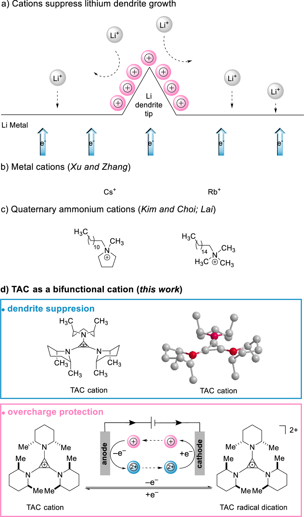
During the electrochemical plating/stripping reaction, sharp Li dendritic projections can form and pierce through a porous separator, resulting in electrical shorting of a Li cell [5,6]. Due to the difficulty in detection and mitigation, the accumulative effect can make the cell undergo severe thermal runaway and even catch fire or cause an explosion. To control dendrites’ growth, considerable efforts have been dedicated to developing a stable Li/electrolyte interface [7–9], improving the tolerance of the separator towards dendrites [10,11] etc. Among those strategies, electrolyte additives have been of high interest due to their rich chemistry and practical applicability. In pioneering work, Xu and Zhang proposed an electrostatic shield mechanism for dendrite suppression (Fig. 1a) [12]. During lithium plating, selected cation-based additives (Cs and Rb, Fig. 1b) can form a positively charged electrostatic shield around Li dendrite tips; thus, the approaching Li cations can be shunted to deposit on an adjacent Li surface and form a uniform Li plating. Compared with other film-forming additives [9], cation additives are not consumable, and thus can provide protection during long cycles. However, those cations may become ineffective at high current densities due to a limited diffusion rate since the concentration is low. The under-potential reduction may also lead to an insufficient shielding on the fast-growing Li tips [13]. Besides metal cations, organic cations might be a promising alternative since their structures can be designed and tailored to fit the battery system. To guarantee a highly efficient shielding effect on demand, the cations should have: 1) a resistance to reduction by Li; 2) a high solubility; 3) a sound diffusivity and ionic mobility; 4) a moderate solvability with electrolyte solvent molecules. This list of requirements may well explain why suitable candidates are seldom reported. Only very recently, Kim, Choi and Lai, respectively, reported two types of quaternary ammonium cations that seem effective (Fig. 1c) [14–15]. Still, devising a more structure-tunable organic cation remains an open challenge.
Fig. 1.

a) A schematic illustration of cation-based electrolyte additives for dendrite suppression; b) metal cations; c) quaternary ammonium cations and d) TAC cation.
Another common safety hazard is overcharge abuse, which can trigger a catastrophic failure due to the sudden release of the pre-stored electrochemical energy [16–18]. To prevent an overcharge, technologies such as external voltage regulators and shutdown electrolyte additives have been proven effective [19,20]. Nevertheless, these approaches would either add extra complexity/weight to the battery management system or permanently disable the cell after overcharging. As an alternative, a small amount of redox shuttle additive can reversibly protect the cell from overcharging by limiting the cell voltage to lower than the molecules’ redox potential [21–26]. The redox-activity of trisaminocyclopropenium (TAC) cations has been known since the 1970s [27–31]. Recently, we reported TAC as the first cation-based redox shuttle additive for sodium-ion batteries’ overcharge protection [32] and an effective electrophotocatalyst [33–34].
In this Communication, we report that TAC can not only prevent the overcharge of Li-based batteries, but also mitigate dendrite growth on a Li anode during charging (Fig. 1d). With a large and bulky positively charged framework, TAC can effectively form an electrostatic shield on dendrite tips and prevent their further growth. Moreover, TAC can reversibly undergo a single-electron oxidation to furnish a very stable dication, which can provide overcharge protection for the batteries. Such peculiar bi-functionality of additives for building safer batteries is reported for the first time.
2. Results and discussion
2.1. Physicochemical properties of TAC cation.
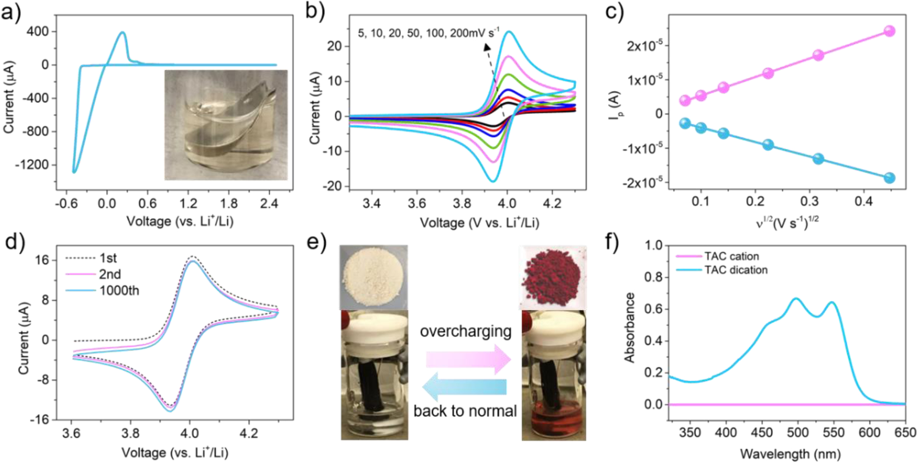
In order to explore the reduction stability of TAC on Li metal, cyclic voltammetry (CV) was carried out on the TAC electrolyte. As can be seen in Fig. 2a, only a pair of Li plating/stripping peaks was observed. In addition, the inset photograph shows that a Li disk stored in a TAC electrolyte solution after six months remained a metallic color with no generation of air bubbles. These results indicate a high reduction-resistant property of the TAC cation toward the Li surface. Fig. 2b shows the reversibility of the redox reaction of TAC. As the scan rate increased from 5 mV s−1 to 200 mV s−1, a series of well-defined redox peaks occurred at ~4.03 V (vs. Li+/Li). The diffusion coefficient of TAC was further calculated to be 2×10⁻⁶ cm−2 s−1 as shown in Fig. 2c, which was consistent with that of the redox shuttles reported previously [21–23]. After 1000 CV scans as shown in Fig. 2d, TAC still presented a very high electro-reversibility with no decrease of current intensity or increase of overpotential.
Fig. 2.

a) Li plating/stripping behaviour in electrolyte containing 50 mM TAC, the inset is a Li disk stored in the same electrolyte after six months; b) cyclic voltammograms at various scan rates; c) plots of peak current vs square root of the scan rate and linear fits; d) cyclic voltammograms scanned at 100 mV s−1; e) photographs of the as-synthesized TAC cation salt and dication salt, photographs of holding a electrochemical device contained TAC cation electrolyte at a constant-potential of 4.1 V (vs. Li+/Li); f) UV-vis spectra of TAC cation and dication solutions.
Interestingly, a unique electrochromic behavior occurred during the redox reaction as displayed in Fig. 2e. The TAC solution exhibited a rapid transfer from colorless to red at 4.1 V (vs. Li+/Li), and the red color disappeared once the polarization voltage was removed. The UV-vis spectrum in Fig. 2f displayed three new peaks at ~450, ~500 and ~550 nm in the TAC dication solution compared with the TAC cation solution. This electrochromic phenomenon implies that TAC can also serve as a visualized overcharge indicator reflecting the safety status of a device during operation. Other parameters such as solubility and viscosity were also investigated. The baseline electrolyte can roughly dissolve up to ~0.5 M TAC cation salt. An electrolyte containing 0.1 M TAC was down selected to be the optimal concentration and was used throughout the rest of the study. The viscosity of a 0.1 M TAC electrolyte is 2.78 mPa compared with 2.43 mPa of baseline electrolyte.
2.2. Electrochemical performance of Li plating/stripping in TAC electrolyte.
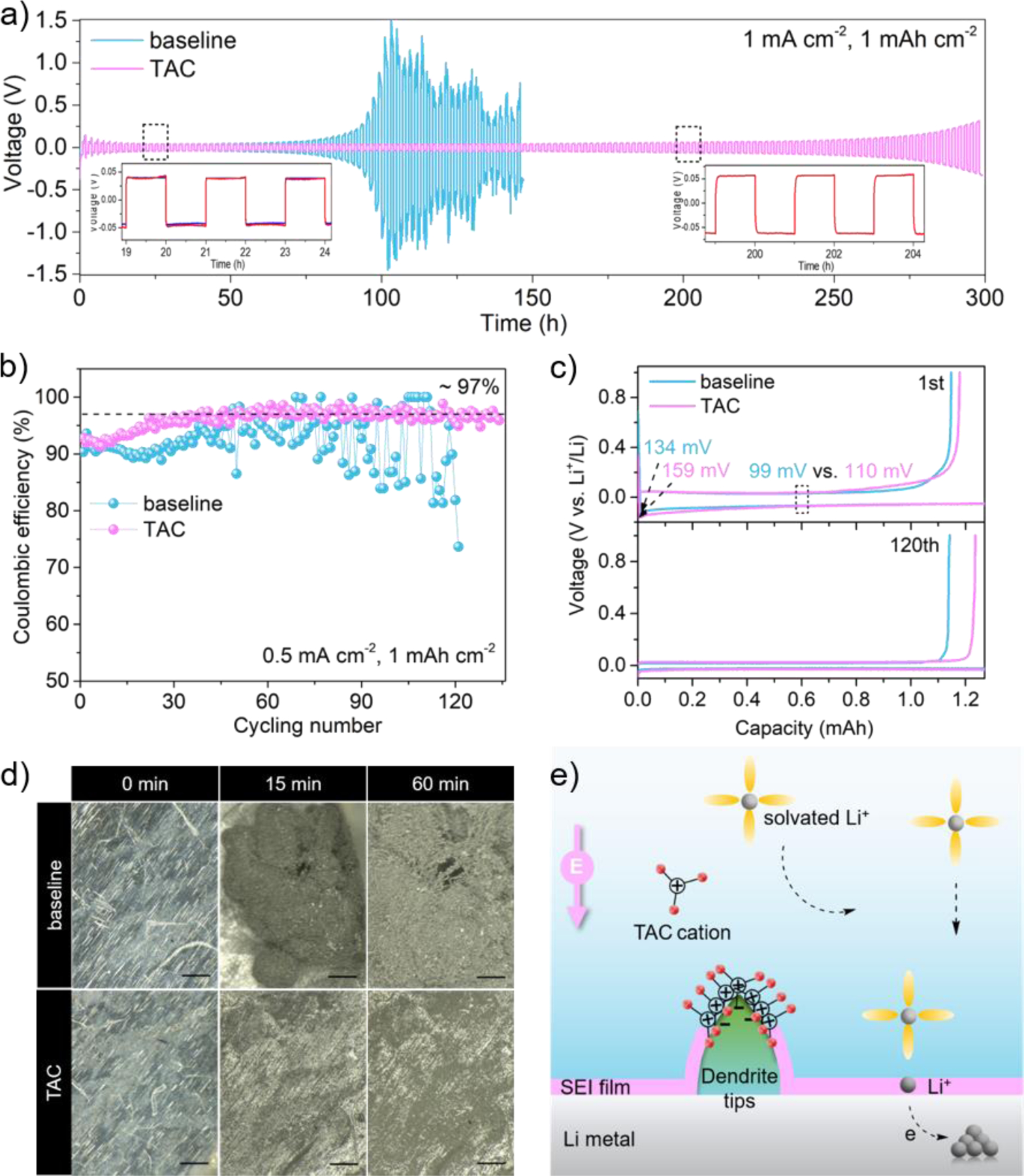
To investigate the role of TAC cation on dendrite suppression, polarization profiles of Li|Li symmetric cells were first cycled at 1 mA cm−2 rate for 1-hour duration. As displayed in Fig. 3a, the cell with baseline electrolyte exhibits increasing voltage hysteresis after 90 h, followed by severe fluctuations due to the huge impedance after cycling. In contrast, the cell with TAC containing an electrolyte was stable after cycling for 300 h. Coulombic efficiencies (CEs) of Li|Cu asymmetric cells cycled at 0.5 mA cm−2 rate in 1 h duration were next evaluated. The results are shown in Fig. 3b. The average CE in the baseline electrolyte dropped below 90% after 49 cycles while an average CE of 97% is preserved in the TAC electrolyte throughout 135 cycles. As shown in Fig. 3c, the slightly larger nucleation potential and higher polarization during the first cycle in the TAC electrolyte could be attributed to the slower ion mobility in a more viscous electrolyte. Then, in-situ optical microscopic images were compared under a harsh Li plating condition of 4.0 mA cm-2. As displayed in Fig. 3d, highly dendritic and mossy Li formed after 15 min in the baseline electrolyte and evolved into filament morphology after 60 min. These dead Li can lead to a poor CE and an increased cell impedance. In contrast, a relatively uniform Li deposition was observed in the TAC electrolyte throughout the test.
Fig. 3.

Electrochemical performance of Li plating/stripping in TAC electrolyte. a) Voltage profiles of Li|Li symmetric cells cycling at 1 mA cm−2 1 mAh cm−2; b) Coulombic efficiencies of Li|Cu asymmetric cells cycling at 0.5 mA cm−2 1 mAh cm−2 and c) the voltage profiles of Li|Cu cell at 1st and 120th; d) in-situ optical microscopic images during Li plating process at 4 mA cm−2, scale bar 200 μm; e) schematic illustration of a cation-shield mechanism. Note: the TAC cation is not drawn to scale.
Electrochemical impedance spectroscopy (EIS) and X-ray photoelectron spectroscopy (XPS) analysis were employed to study the stability and chemical composition of the formed SEI on Li surface. As displayed in Fig. S3a, EIS of Li|Li symmetric cells were compared between the two electrolytes after the first and second cycle, respectively. Distribution of relaxation times (DRT) calculation was further conducted to better distinguish the impedance-related process. DRT plots can provide direct access to not only the rate constant (relaxation time) of each physical and electrochemical step, but also the polarization resistance (relaxation amplitudes) from the corresponding peaks. As displayed from Fig. S3b, the DRT plots exhibit two significant peaks, implying two constant phase elements (CPE) in the equivalent circuit. Specifically, the green area related kinetic process corresponds to the interfacial charge transfer reaction (RCT) while the yellow area corresponds to the Li+ diffusion across SEI layer (RSEI). After the 2nd cycle, the symmetric cell in baseline electrolyte shows a hysteresis in charge transfer process and an increase in RCT (from 73 ohm to 82 ohm). By contrast, the cell in TAC electrolyte shows a significantly improved kinetic process with a reduced RSEI (from 41 ohm to 15 ohm) and RCT (from 44 ohm to 34 ohm), indicating the formation of a more stable solid-liquid interface driven by TAC cation. The XPS spectra are displayed in Fig. S4. The F1s spectra (Fig. S4a) of both samples shows a strong peak at ~684.8 eV and a weak peak at ~686.6 eV, assigned to LiF and LixPyOFz species, respectively. O1s spectra (Fig. S4b) exhibits a peak at 533.3 eV, representing C-O-C group from ROCO2Li compound, caused by linear DMC decomposition. Another two peaks at ~531 eV and ~532 eV is assigned to the LiOH and Li2CO3 compound, which are the main SEI components from carbonates. In the TAC electrolyte, more Li2CO3 species are formed, which is reported to benefit the cyclability of Li metal electrode.[35] The C1s spectra (Fig. S4c) shows three peaks at ~284.8 eV, ~286.1 eV and ~288.1 eV, representing C-C, C-O and Li-CO2- group, respectively. The C-H and C-O compounds are derived from FEC decomposition and Li-CO2-R compound is arise from DMC. In the TAC electrolyte, the Li-CO2-R peak is weaker, indicating a suppression of DMC decomposition. For N1s and Cl1s spectra (Fig. S4d-e), no signal was detected in both electrolytes, indicating the inertness of TAC cation on the Li surface during repeated cycling. Generally, TAC cations promote the formation of a more favorable SEI on Li surface without reducing to become the components of SEI.
A cation-shield mechanism is proposed and illustrated in Fig. 3e. It is well established that the plating process can unavoidably generate protuberant tips on which electric charges tend to accumulate. The TAC cations can be absorbed on those tips without being reduced via electrostatic attraction. Thus, a lithiophobic protective layer can be formed due to its bulky scaffold with branched nonpolar groups. The arriving Li+ was repelled and deposited on the adjacent flat Li surface, thus generating a dendrite-free Li deposition.
2.3. Cell performance during overcharging and normal operation.
Next, we turned to evaluate the overcharge protection of the TAC electrolyte. LiFePO4 (LFP) was selected as the cathode. Recently, BYD Company unveiled a “blade battery” technology, returning LFP batteries to the spotlight of the passenger vehicle market as a competitive candidate compared with the high energy density LiNi1–y–zMnyCozO2 (NMC) batteries [36]. The robust blade design can lead to a 50% increase of space utilization compared with the conventional design at the pack level. Li metal, Li4Ti5O12 (LTO) and graphite were selected as potential anodes, respectively.
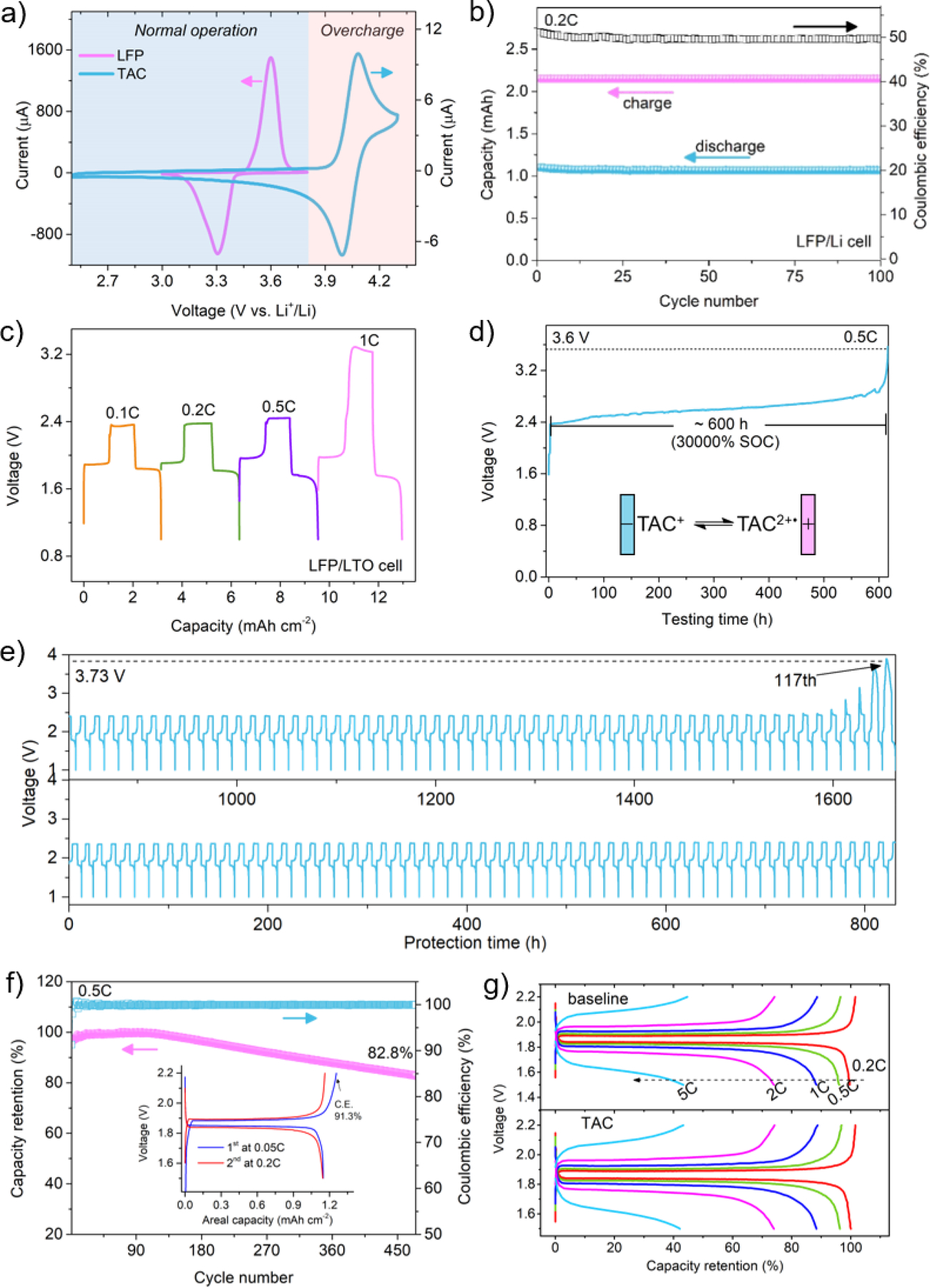
As shown in Fig. 4a, the oxidation peak of TAC cation occurs 300 mV after the full completion of the delithiation process of LFP, while the reduction of TAC dication takes place 600 mV before the beginning of the lithiation process of LFP. This indicates that TAC can remain electro-inactive during the normal lithiation/delithiation process of a LFP cathode. As shown in Fig. 4b, LFP/Li cell maintained a stable CE of ~50% and a discharge capacity of ~162 mAh g−1 throughout the 100 overcharge cycles at 0.5 C. As shown in Fig. S5a, the LFP/LTO cell exhibits a discharge voltage plateau at ~1.8 V and a protection voltage plateau at ~2.4 V. No additional polarization was observed in comparison with that of the LFP/Li and LTO/Li cell. The TAC’s capacity of overcharge protection for a LFP/LTO cell at different current densities is displayed in Fig. 4c. TAC can provide protection up to 1 C rate charge. Fig. 4d shows the overcharge protection during a continuous overcharge at 0.5 C of a LFP/LTO cell. ~600 h (30000% SOC) protection was sustained before losing voltage clamping effect. As shown in Fig. 4e and Fig. S5b, the LPF/LTO cell survives 117 cycles (~1640 h) with 100% overcharge at 0.2 C. Moreover, as shown in Fig. S6, the cell survives 77 cycles (~2200 h) and 63 cycles (~354 h) with 100% overcharge at 0.1 C and 0.5 C, respectively.
Fig. 4.

a) Comparison of cyclic voltammograms between LFP and TAC at a scan rate of 0.1 mV s−1 and 20 mV s−1, respectively; b) cycling performance of LFP/Li cell with 100% overcharge; LFP/LTO cell: c) voltage profiles with 100% overcharge at different current rates; d) continuously charging voltage profile at 0.5 C; e) cycling performance with 100% overcharge at 0.2 C; f) normal cycling performance at 0.5 C between 1.5–2.2 V, inset is the voltage profiles of the first two cycles; g) normal rate performance between 1.5–2.2 V.
Electrochemical performance during normal operation of LPF/LTO cell (1.5–2.2 V) is an indispensable prerequisite before the redox shuttle’s practical application. Cycling performance is shown in Fig. 4f. The LFP/LTO cell has a capacity retention of 82.8% after 475 cycles with a steady CE of nearly 100%. The inset two formation cycles have a CE of 91.3% and 98%, respectively. No change in capacity retention can be observed at the rate up to 5 C (Fig. 4g). Despite the higher viscosity, TAC cation can contribute to overall ionic conductivity. Generally, the normal operation of the LFP/LTO cell is barely affected by the TAC additive. Other than the LFP/LTO cell, the LFP/graphite cell was also studied and displayed in Fig. S7.
3. Conclusion
In summary, this study explored trisaminocyclopropenium cation as a bi-functional electrolyte additive for dendrite suppression and overcharge protection in Li-based batteries. With a mere 0.1 M addition, the Li|Li symmetric cell exhibits a stable cycling for 300 h at 1 mA cm−2, two times longer than in the baseline electrolyte. Also, the TAC electrolyte can provide 117 cycles (~1640 h) of reversible overcharge protection under 0.2 C with 100% overcharge for the LiFePO4/Li4Ti5O12 cell.
Supplementary Material
References
- [1].Bruce PG, Freunberger SA, Hardwick LJ, Tarascon J-M, Nat. Mater 11 (2012) 19–29. [DOI] [PubMed] [Google Scholar]
- [2].Wang Q, Ping P, Zhao X, Chu G, Sun J, Chen C, J. Power Sources 208 (2012) 210–224 [Google Scholar]
- [3].Feng X, Ouyang M, Liu X, Lu L, Xia Y, He X, Energy Storage Mater 10 (2018) 246–267 [Google Scholar]
- [4].Finegan DP, Scheel M, Robinson JB, Tjaden B, Hunt I, Mason TJ, Millichamp J, Di Michiel M, Offer GJ, Hinds G, Brett DJL, Shearing PR, Nature Comm 6 (2015) 6924. [DOI] [PMC free article] [PubMed] [Google Scholar]
- [5].Kushima A, So KP, Su C, Bai P, Kuriyama N, Maebashi T, Fujiwara Y, Bazant MZ, Li J, Nano Energy 32 (2017) 271–279 [Google Scholar]
- [6].Pei A, Zheng G, Shi F, Li Y, Cui Y, Nano letters 17 (2017) 1132–1139. [DOI] [PubMed] [Google Scholar]
- [7].Lin D, Liu Y, Cui Y. Nat. Nanotechnol 12 (2017) 194. [DOI] [PubMed] [Google Scholar]
- [8].Liu H, Cheng X-B, Huang J-Q, Yuan H, Lu Y, Yan C, Zhu G-L, Xu R, Zhao C-Z, Hou L-P, He C, Kaskel S, Zhang Q. ACS Energy Lett 5 (2020) 833–843 [Google Scholar]
- [9].Zhang X-Q, Cheng X-B, Chen X, Yan C, Zhang Q, Adv. Funct. Mater 27 (2017) 1605989. [Google Scholar]
- [10].Liu K, Zhuo D, Lee H-W, Liu W, Lin D, Lu Y, Cui Y, Adv. Mater 29 (2017) 1603987. [DOI] [PubMed] [Google Scholar]
- [11].Gonzalez MS, Yan Q, Holoubek J, Wu Z, Zhou H, Patterson N, Petrova V, Liu H, Liu P, Adv. Mater 32 (2020) 1906836. [DOI] [PubMed] [Google Scholar]
- [12].Ding F, Xu W, Graff GL, Zhang J, Sushko ML, Chen X, Shao Y, Engelhard MH, Nie Z, Xiao J, Liu X, Sushko PV, Liu J, Zhang J-G, J. Am. Chem. Soc 135 (2013) 4450–4456. [DOI] [PubMed] [Google Scholar]
- [13].Ding F, Xu W, Chen X, Zhang J, Shao Y, Engelhard MH, Zhang Y, Blake TA, Graff GL, Liu X, Zhang J-G, J. Phys. Chem. C 118 (2014) 4043–4049. [Google Scholar]
- [14].Dai H, Xi K, Liu X, Lai C, Zhang S. J. Am. Chem. Soc 140 (2018) 17515–17521. [DOI] [PubMed] [Google Scholar]
- [15].Yoo D-J, Kim KJ, Choi JW, Adv. Energy Mater 8 (2018) 1702744. [Google Scholar]
- [16].Zhu X, Wang Z, Wang Y, Wang H, Wang C, Tong L, M. Y, Energy 169 (2019) 868–880 [Google Scholar]
- [17].Nam KW, Bak SM, Hu E, Yu X, Zhou Y, Wang X, Wu L, Zhu Y, Chung KY, Yang XQ, Adv. Funct. Mater 23 (2013) 1047–1063. [Google Scholar]
- [18].Belov D, Yang MH. J. Solid State Electrochem 12 (2008) 885–894. [Google Scholar]
- [19].Liu K, Liu Y, Lin D, Pei A, Cui Y, Sci. Adv 2018, 4, eaas9820. [DOI] [PMC free article] [PubMed] [Google Scholar]
- [20].Chen Z, Qin Y, Amine K, Electrochim. Acta 54 (2009) 5605–5613. [Google Scholar]
- [21].Dahn JR, Jiang J, Moshurchak LM, Fleischauer MD, Buhrmester C, Krause LJ, J. Electrochem. Soc 152 (2005) A1283–A1289 [Google Scholar]
- [22].Weng W, Huang J, Shkrob IA, Zhang L, Zhang Z, Adv. Energy Mater 6 (2016) 1600795 [Google Scholar]
- [23].Kaur AP, Elliott CF, Ergun S, Odom SA, J. Electrochem. Soc 163 (2016) A1–A7. [Google Scholar]
- [24].Zhang L, Zhang Z, Wu H, Amine K, Energy Environ. Sci 4 (2011) 2858–2862. [Google Scholar]
- [25].Zhang L, Zhang Z, Redfern PC, Curtiss LA, Amine K, Energy Environ. Sci 5 (2012) 8204–8207. [Google Scholar]
- [26].Moshurchak LM, Buhrmester C, Dahn JR, J. Electrochem. Soc 155 (2008) A129–A131. [Google Scholar]
- [27].Gerson F, Plattner G, Yoshida Z, Mol. Phys 21 (1971) 1027–1032. [Google Scholar]
- [28].Weiss R, Schloter K, Tetrahedron Lett 16 (1975) 3491–3494. [Google Scholar]
- [29].Johnson RW, Tetrahedron Lett 17 (1976) 589–592. [Google Scholar]
- [30].Bandar JS, Lambert TH, Synthesis 45 (2013) 2485–2498. [Google Scholar]
- [31].Sevov CS, Samaroo SK, Sanford MS, Adv. Energy Mater 7 (2017) 1602027. [Google Scholar]
- [32].Ji W, Huang H, Zhang X, Zheng D, Ding T, Lambert TH, Qu D, Nano Energy 72 (2020) 104705. [DOI] [PMC free article] [PubMed] [Google Scholar]
- [33].Huang H, Strater ZM, Rauch M, Shee J, Sisto TJ, Nuckolls C, Lambert TH, Angew. Chem. Int. Ed 58 (2019) 13318–13322. [DOI] [PMC free article] [PubMed] [Google Scholar]
- [34].Huang H, Strater ZM, Lambert TH, J. Am. Chem. Soc 142 (2020) 1698–1703. [DOI] [PMC free article] [PubMed] [Google Scholar]
- [35].Ding F, Xu W, Chen X, Zhang J, Engelhard MH, Zhang Y, Johnson BR, Crum JV, Blake TA, Liu X, and Zhang J-G, J. Electrochem. Soc 160 (2013) A1894–A1901. [Google Scholar]
- [36]. https://en.byd.com/news-posts/byds-new-blade-battery-set-to-redefine-ev-safety-standards/.
Associated Data
This section collects any data citations, data availability statements, or supplementary materials included in this article.


