

Abstract

A series of n-octadecane/mesoporous silica (C18/MS) shape-stabilized phase change materials (SSPCMs) with varying C18 content were prepared, and the effects of adsorbed C18 distributed within porous MS on the thermal properties were analyzed. As characterized, C18 was first infiltrated into the mesoporous space, resulting in a SSPCM with a maximum of ∼52 wt % C18. Additional adsorption of C18 occurred on the external surface of MS. Consequently, the optimum 70 wt % C18 SSPCM had no C18 leakage and exhibited a heat storage capacity of 135.6 J/g and crystallinity of 83.5%, which were much larger than those of 52 wt % C18 SSPCM (60.2 J/g and 68.2%, respectively). The prepared C18/MS SSPCMs showed excellent thermal stability and thermal reliability up to 1000 accelerated thermal cycle tests. Moreover, the C18/MS SSPCM incorporated in gypsum effectively reduced the temperature changes compared with the original gypsum, suggesting the promising application of the prepared C18/MS SSPCM for energy-saving building applications.
1. Introduction
Using shape-stabilized phase change materials (SSPCMs) comprised of phase change materials (PCMs) impregnated in porous matrixes for thermal energy storage (TES) in buildings can smooth the temperature fluctuation and reduce energy consumption.1,2 PCMs are active thermal energy storage materials that can store large amounts of latent heat during melting/solidification within a small phase change temperature range. In turn, the leakage of liquid PCMs during melting is prevented by the capillary and surface tension forces of the porous matrixes.3 Practically, SSPCMs are usually incorporated with construction materials such as gypsum, mortar, cement, and brick.4,5 According to the thermal comfort (20 < T < 26 °C) of human beings, PCMs with a phase change temperature of 18–30 °C are most suitable.2 During the daytime, PCMs absorb heat and melt due to temperature rise; at night, as the temperature decreases, they release the stored heat and solidify. Several organic PCMs (paraffins,6,7 biobased PCMs,8 fatty alcohols9) and inorganic PCMs (CaCl2·6H2O,10 Na2SO4·10H2O11) have been investigated for building applications. Inorganic PCMs usually show advantages of low cost, flame retardance, and relatively high latent heat storage capacity. However, severe supercooling, phase segregation, and strong corrosivity still restrict their applications.12,13 To overcome these limitations, organic PCMs have gained increasing attention for preparing SSPCMs.14 Of the organic PCMs, n-octadecane is considered a potential candidate for its high heat storage capacity and high chemical and thermal stability after a long-term utilization period.15,16
Porous supports allow us to stabilize PCMs in nanopores and continue to maintain the PCMs after multiple melting/solidification cycles. Pore size is an important parameter, which greatly affects the PCM storage amount and thermal properties of SSPCMs. Very small pores i.e., micropores, can only adsorb a small amount of PCM due to the low pore volume, leading to poor latent heat storage capacity. In contrast, large pores, i.e., macropores, can result in high PCM adsorption but cause leakage due to insufficient capillary and surface tension forces. Practically, mesoporous structures are often used for high PCM stability and enhanced PCM adsorption. Commonly employed porous supports include silica,17,18 carbon-based materials,13,19 organic porous polymers,12,20,21 and metal foams.22 Of them, porous silica has been considered the most promising candidate for large-scale building applications due to its low cost, high availability, high thermal resistance, and high surface adsorption. For example, Min et al.23 used mesoporous silica (MS) as a porous matrix for adsorption of poly(ethylene glycol) (PEG) PCM, which resulted in a PEG/MS SSPCM up to 80 wt % PEG. Chen et al.24 prepared an MS to support myristic acid (MA), and up to 65 wt % MA could be stabilized in the MA/MS SSPCM. The high PCM contents in the SSPCMs greatly benefited the thermal performance since the latent heat storage capacity was directly proportional to the PCM amount. It can be calculated that the MS supports from the as-mentioned studies provide limited mesoporous space for infiltrating PCMs so that the volume of mesopores occupied is only about 40 wt % PEG by Min et al.23 or 50 wt % MA by Chen et al.24 Thanks to the large surface area of microsized silica particles, PCMs can be continued to be adsorbed onto the external surface of MS particles with enough physical forces to maintain the stability of the resultant SSPCMs. Thus, PCM contents were practically much larger than their maximum amounts calculated from mesoporous adsorption capability of siliceous materials, i.e., 80 wt % PEG for PEG/MS SSPCM and 65 wt % MA for MA/MS SSPCM. In other words, the external surface of MS played the role of adsorption sites for PCMs. However, the behaviors of PCMs residing on the external surface and their role in affecting thermal properties have not been fully clarified in the literature. In addition, it is worth mentioning that different PCM materials can exhibit unique physicochemical interactions with the porous host. Hence, C18 exhibits different performances compared with PEG and MA if it was loaded in porous silica. However, to the best of our knowledge, the insight into C18 distribution in mesoporous silica and its thermal properties has never been reported.
In this study, the chemistry insights into the C18 distribution between the mesopores and the external surface of mesoporous silica (MS) and the thermal properties of the C18/MS SSPCM were deeply investigated. A series of C18/MS SSPCMs with increasing C18 contents (40, 52, 60, 70, and 80 wt %) were prepared and characterized using N2 adsorption–desorption isotherms, Fourier transform infrared (FT-IR) spectroscopy, thermogravimetric analysis (TGA), differential scanning calorimetry (DSC), and X-ray diffraction (XRD). The obtained materials were examined for potential application in the field of buildings by incorporating SSPCM with gypsum.
2. Results and Discussion
2.1. Characterization
Figure 1a,b shows the N2 adsorption–desorption isotherms and pore size distribution (PSD) of MS compared with C18/MS SSPCMs, respectively, and the detailed porosities are exhibited in Table 1. In Figure 1a, MS presented a type IV isotherm with a capillary condensation step that occurred at a P/P0 (N2 relative pressure) of approximately 0.7–0.9 and a H1 hysteresis loop as classified by IUPAC, indicating a mesoporous structure. The pore size distribution (PSD) of MS (Figure 1b) showed that the mesopores were distributed in a broad range of 5–35 nm with a peak at 16.6 nm. The specific surface area and pore volume obtained were 291 m2/g and 1.42 cm3/g, respectively. Assuming that the amount of C18 fully occupies the pore volume of MS, we obtain Vp·ρ·WMS,25 and thus, the total mass of SSPCM is WMS + Vp·ρ·WMS. The maximum content (ϕMAX) of C18 loaded in mesopores could be calculated using eq 1
| 1 |
where Vp is the specific pore volume of MS, ρ is the density of liquid octadecane (0.77 g/cm3), and WMS is the mass of MS.
Figure 1.

(a) N2 adsorption–desorption isotherms and (b) pore size distributions of MS compared with the prepared SSPCMs (40, 52, 60, 70, and 80 wt % C18) and (c) FT-IR spectra compared among MS, C18, and the prepared SSPCMs (40 and 80 wt % C18).
Table 1. Porosities and Thermal Properties of the MS, C18, and C18/MS SSPCMs.
|
porosity |
melting |
solidification |
|||||||||||
|---|---|---|---|---|---|---|---|---|---|---|---|---|---|
| Va (cm3/g) | d (nm) | S (m2/g) | TM,pore (°C) | TM,surf (°C) | ΔHM,pore (J/g) | ΔHM,surf (J/g) | ΔHM,tot (J/g) | TS,pore (°C) | TS,surf (°C) | ΔHS,pore (J/g) | ΔHS,surf (J/g) | ΔHS,tot (J/g) | |
| MS | 1.45 | 16.6 | 291 | ||||||||||
| 40 wt % | 0.53 | 22.4 | 97 | 22.3 | 60.2 | 0 | 60.2 | 21.5 | 59.5 | 0 | 59.5 | ||
| 52 wt % | 0.22 | 44 | 22.1 | 81.7 | 0 | 81.7 | 22.9 | 82.1 | 0 | 82.1 | |||
| 60 wt % | 0.087 | 34 | 22.4 | 29.3 | 64.7 | 40.4 | 105.1 | 24.1 | 27.0 | 79.8 | 24.5 | 104.3 | |
| 70 wt % | 0.086 | 21 | 24.2 | 29.1 | 56.7 | 78.9 | 135.6 | 23.9 | 27.6 | 67.2 | 67.2 | 134.4 | |
| 80 wt % | 0.04 | 9 | 24.7 | 29.3 | 38.9 | 125.3 | 164.2 | 23.0 | 27.9 | 25.5 | 139.4 | 164.9 | |
| C18 | 29.0 | 0 | 230.6 | 230.6 | 28.1 | 0 | 231.4 | 231.4 | |||||
The pore volume was calculated at P/P0 of 0.95.
ϕMAX was computed to be approximately 52 wt % for the mesopores. This means that all mesopores in MS are fully loaded as the adsorbed C18 reached the ϕMAX value. For the prepared 40 wt % SSPCM (%C18 < ϕMAX), the N2 sorption isotherm (Figure 1a) exhibited a significant reduction in N2 adsorption. Additionally, the PSD (Figure 1b) showed a strong decrease of mesopores below ∼17 nm, and the peak was shifted to 22.4 nm, larger than that of pristine MS. These indicated that the PCM initially filled the smaller mesopores and then larger ones during the impregnation process, thus resulting in the shift of the PSD peak. At 52 wt % C18 load, the SSPCM showed almost no N2 uptake with the disappearance of the PSD peak, indicating that the mesopores were fully filled with the PCM. Therefore, as the C18 contents surpassed ϕMAX, i.e., 60, 70, and 80 wt %, the PCM was adsorbed onto the external surface, filling interparticle voids. These additional contents accounted for about 17, 37, and 58 wt % C18 residing on external surfaces for the 60, 70, and 80% C18 SSPCMs, respectively.
Figure 1c presents FT-IR spectra of two representatives of 40 and 80 wt % SSPCMs in comparison with pristine MS and C18. The two SSPCMs exhibited combined characteristics of pure MS and C18 with no new peaks observed. For example, the peaks at 462, 802, and 1095 cm–1 could be assigned to bending vibration, symmetric stretching vibration, and asymmetric stretching vibration of the siloxane group (Si–O–Si) inherited from MS, respectively. The peak at 1627 cm–1 was characterized for the bending mode of adsorbed water, while the overlapped stretching vibration of adsorbed water and surface silanol groups (−Si–OH) was observed at 3245 cm–1.26 Meanwhile, the inherent properties of C18 were presented for the bending vibration peaks at 1377 and 1465 cm–1 and the stretching vibration peaks at 2854, 2915, and 2962 cm–1 assigned to the −C–H group. In addition, the peak at 725 cm–1 was attributed to the −CH2– in-plane rocking vibration. These results demonstrated that C18 and MS were intact after the impregnation process and physically compounded without chemical reactions. Additionally, thermogravimetric analysis of the prepared SSPCMs showed C18 fractions of 41.5, 51.4, 60.6, 69.2, and 79.1 wt %, corresponding to the initially added C18 contents of 40, 52, 60, 70, and 80 wt % C18/MS SSPCMs, respectively (see Figure 6a).
Figure 6.

(a) Thermogravimetric analysis (TGA) curves and (b) derivative thermogravimetry (DTG) curves of C18 and the prepared SSPCMs (40, 52, 60, 70, and 80 wt % C18).
Figure 2 presents the SEM images of the prepared C18/MS SSPCMs compared with pristine MS. MS (Figure 2a) shows irregular mesopores generated from aggregated nanoparticles and rough nanoparticle surfaces, favoring both pore and surface adsorption of PCM. Meanwhile, some pores of MS in the 40 wt % SSPCM (Figure 2b) were occupied by C18 PCM, while the MS surface was still free of C18, indicating that the doped C18 was adsorbed into the pores of MS. As the C18 content reached 52 wt % (Figure 2c), the MS pores seemed to have full adsorption of C18. Such C18 adsorption almost occurred on the surface of MS upon further increasing the C18 content to 60, 70, and 80 wt % (Figure 2d–f, respectively). In addition, the SEM image of 80 wt % SSPCM (Figure 2f) shows bulk lumps of C18 on the surface, possibly due to excessive C18 produced after fully covering the surface and interparticle voids of MS. The impregnation process of C18 into MS is illustrated in Figure 3.
Figure 2.

SEM images of (a) MS, (b) 40 wt % C18/MS, (c) 52 wt % C18/MS, (d) 60 wt % C18/MS, (e) 70 wt % C18/MS, and (f) 80 wt % C18/MS.
Figure 3.
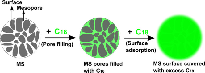
Illustration of the infiltration process of C18 into MS at %C18 exceeding the ϕMAX value.
2.2. Thermal Properties of the Prepared SSPCMs
Figure 4 shows the DSC curves of the pure C18 and prepared SSPCMs. The detailed melting/solidification temperatures of C18 residing in mesopores (TM,pore/TS,pore) and on the external surface (TM,surf/TS,surf) can be seen in Table 1. As shown, the 40 and 52 wt % SSPCMs presented single phase change peaks during melting and solidification, which was similar to pure C18, although their endothermic peaks shifted to lower temperatures by approximately 7 °C compared to pure C18. This could be attributed to the strain in C18 molecules as they are narrowly confined in the mesopores.25 However, an additional phase change peak appeared in both melting and solidification for the SSPCMs with 60, 70, and 80 wt % C18. This suggests a different phase change behavior for those of C18 residing on the external surface of the MS. As the PCMs residing on the external surface have larger space, these molecules suffered less from the strain. This resulted in higher phase change temperatures than for those residing in the mesopores, hence approaching the temperature of pure C18.
Figure 4.

(a) Melting DSC curves and (b) solidification DSC curves of C18 and the prepared SSPCMs.
The latent heat storage capacity or phase change enthalpy including the melting/solidification enthalpy of C18 residing in mesopores (ΔHM,pore/ΔHS,pore), on the external surface (ΔHM,surf/ΔHS,surf), and total melting/solidification enthalpy (ΔHM,tot/ΔHS,tot) are shown in Table 1. The total melting and solidification enthalpy increased with increasing C18 content, ranging from 60.2 and 59.5 J/g for the 40 wt % SSPCM to 165.6 and 163.2 J/g for the 80 wt % SSPCM, respectively. This was because the enthalpy of the SSPCMs was solely generated from C18 and became larger with increasing C18 content. The lower enthalpy of the SSPCMs compared to that of pure C18 (230.6 and 231.4 J/g for melting and solidification enthalpy, respectively) indicates the formation of a nonfreezable layer at the interfacial regions between PCM and pore walls during the infiltration of C18, which cannot be crystallized even at a temperature below the solidification point of the PCM. This phenomenon is known to suppress the crystallinity of the SSPCM and thus did not play a role in thermal change.18,25,27 Meanwhile, such a nonfreezable layer can be minimized at a high C18 content, leading to increasing enthalpy. To clarify the effects of the nonfreezable layer on the crystallinity of loaded C18, the crystallization fraction (FC (%)) was calculated using eq 2,(28) and the results are illustrated in Figure 5a
| 2 |
where ΔHM,tot and ΔHS,tot are the total melting and solidification enthalpy of the SSPCM, respectively, ΔHM,PCM and ΔHS,PCM are the melting and solidification enthalpy of pure C18, respectively, and x is the relative fraction of PCM in the SSPCM.
Figure 5.

(a) Crystallization fraction and (b) XRD patterns of pure C18 and the prepared SSPCMs (40, 52, 60, 70, and 80% C18).
As shown in Figure 5a, the FC values increased from 64.7 to 91.4% on increasing the C18 content from 40 to 80 wt %, respectively. This was consistent with the steady growth of the XRD peak intensity with the growing C18 content (Figure 5b). The less than 100% crystallization fraction suggested that the crystallinity of the loaded C18 was suppressed by the nonfreezable layer. In the MS porous network, the mesopores generated a much larger surface area than the external surface. The large surface area could lead to a higher fraction of the nonfreezable layer, thus lowering the crystallinity. The FC values increased with the increased C18-content SSPCMs because C18 was increasingly adsorbed onto the external surface. It is noted that ΔFC = 3.4% with the C18 content increasing from 40 to 52 wt % suddenly soared to ΔFC = 7.3% on increasing the C18 content to 60%, then steadily increased at ΔFC = 7.9 and 5.5% with the C18 content reaching 70 and 80 wt %, respectively. The strong increase of the FC value from the 52 wt % SSPCM to 60 wt % SSPCM marked the change in PCM distribution from filling mesopores to the external surface. It was emphasized that the employment of the external surface as a storage cavity greatly enhanced the crystallinity of the SSPCMs compared to that of mesopores, thus benefiting the heat storage capacity. For example, the crystallization fraction increased by 15.3% from the 52 wt % SSPCM (68.2% crystallinity) to the 70 wt % SSPCM (83.5% crystallinity), corresponding to an increase by 66% from 81.7 to 135.6 J/g for the heat storage capacity, respectively. These results suggest that the external surface adsorption of PCM plays an important role in enhancing the thermal properties of the C18/MS SSPCM.
2.3. Thermal Stability and Leakage Resistance
The thermal stability of the prepared SSPCMs compared to that of pure C18 was investigated using TGA, and the results are presented in Figure 6a. All of the samples showed a one-step weight loss because of the thermal decomposition of C18. Pure C18 presented a weight loss of nearly 100% in a temperature range of 100–207 °C. Meanwhile, all of the prepared SSPCMs exhibited a weight loss in a higher temperature range of about 150–225 °C. For precise comparison, the thermal stability was evaluated by the characteristic temperature at a maximum decomposition rate (TMAX) in the DTG curve (Figure 6b). As can be seen, pure C18 showed a TMAX at 203.5 °C while the prepared SSPCMs presented a higher TMAX value of about 230 °C, indicating that the thermal stability of the SSPCMs can be considerably improved by the introduction of the MS matrix. This result suggested that the interactions (capillary and surface tension forces) and interfacial interactions between C18 and functional groups on the MS surface can effectively delay the thermal degradation of the loaded C18.29,30 Moreover, the prepared SSPCMs decomposed at a temperature considerably exceeding the working melting point of C18 (∼30 °C). Therefore, the C18/MS SSPCMs possessed excellent thermal stability during repeated melting/solidification operations.
Figure 7 shows the digital photos of pure C18 and the prepared SSPCMs placed on filter papers for 60 min at 60 °C (∼30 °C higher than the melting point of C18). Pure C18 was totally melted after the thermal treatment. In contrast, no leakage was observed for the SSPCMs with 52, 60, and 70 wt % C18, possibly due to C18 PCM being sustained in the porous framework of MS by capillary and surface tension forces. The 80 wt % SSPCM somehow showed liquid leakage, which could be attributed to the removal of excessive C18. Therefore, MS was capable of holding up to 70 wt % C18 without leakage owing to the additional adsorption of the external surface although the mesopores of MS showed a maximum uptake of 52 wt %.
Figure 7.

Digital photos of C18 and the prepared SSPCMs after 60 min at 60 °C.
2.4. Thermal Reliability
The 70 wt % C18 SSPCM, which had the largest C18 content with no C18 leakage and exhibited a large latent heat storage capacity, was selected for the thermal tests. The cycle durability or thermal reliability of the material was tested over 1000 accelerated thermal cycles, and the melting/solidification DSC curves and melting/solidification latent heat storage capacity during the test are exhibited in Figure 8. The DSC curves were almost unchanged during the 1000 thermal cycles, and the phase change temperatures accordingly remained unaltered. Moreover, the total melting/solidification latent heat storage capacities were also negligibly changed after multiple cycles (ΔHM,tot and ΔHS,tot changed by only 0.9 and 1.3% after 1000 cycles, respectively). These results suggested that the 70 wt % C18/MS SSPCM exhibited excellent thermal reliability to repeatedly perform heat storage and release at a stable phase change temperature and heat storage capacity.
Figure 8.

(a) Melting and (b) solidification DSC curves of the 70 wt % C18/MS SSPCM during 1000 accelerated thermal cycles.
Table 2 compares the latent heat storage capacity of the prepared C18/MS SSPCM to those of other C18-based SSPCMs recently reported. Overall, the prepared SSPCM is comparable and even better than most reported materials in terms of heat storage capacity. Meanwhile, the prepared SSPCM had slightly lower thermal enthalpy than C18/G18 SSPCM and C18/fumed silica SSPCM; however, it has the advantages of simple preparation and cost-effectiveness, promising the potential of large-scale applications.
Table 2. Comparison of Thermal Enthalpy among n-Octadecane-Based SSPCMs.
2.5. Thermal Performance Evaluation of C18/MS SSPCM in Building Materials
Figure 9 shows the temperature rise compared to the original gypsum and gypsum incorporated with 70 wt % C18/MS SSPCM at two mass ratios of SSPCM 10 and 20 wt %. It is undoubtedly seen that the gypsum incorporated with SSPCMs delayed the temperature rise compared to the pristine one, indicating that the composites could effectively store a larger heat due to the additional latent heat absorption of the SSPCM. Based on the tangential method, the temperature profile of the SSPCM-incorporated gypsums can be divided into three steps as follows. The first step of <22 °C and the last step of >30 °C exhibited a temperature increase before and after the melting of the SSPCM driven by the adsorption of sensible heat. The middle step (22–30 °C) showed the temperature increase during the melting of the SSPCM driven by both sensible and latent heat. Thus, a lower slope in temperature rise was observed in the middle step than in the other steps. The result was consistent with the literature where an SSPCM generally possesses much larger latent heat than sensible heat.10,36 Contrastingly, the pristine gypsum showed a quick temperature increase due to lack of latent heat storage, nearly reaching a peak at 41.6 °C after 500 s. For comparison, at the same time (500 s), the temperatures for 10 and 20 wt % SSCPM-incorporated gypsums were 38.5 and 28.2 °C, respectively. These results demonstrated that the C18/MS SSPCM-incorporated gypsum could reduce temperature fluctuation, suitable for energy-saving building applications.
Figure 9.
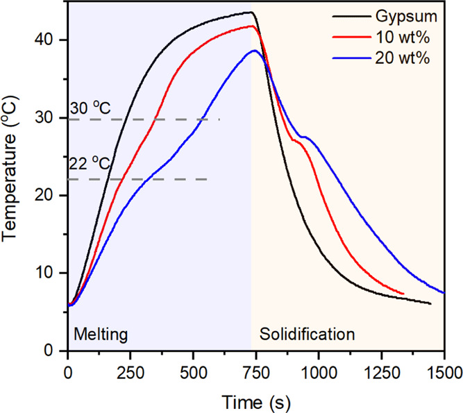
Temperature rise curves of gypsum and SSPCM-incorporated gypsums during a thermal performance evaluation.
3. Conclusions
In this work, the C18/MS SSPCMs were simply prepared and thoroughly characterized using a range of instrumental analyses. The major results were pointed out as follows.
C18 PCM was impregnated into MS by initially filling the mesopores and then the external surface. Such addition of external surface adsorption resulted in an optimal SSPCM of up to 70 wt % C18 content with excellent thermal stability and leakage prevention, where the crystallinity extent increased by ∼15%.
The 70 wt % C18/MS SSPCM exhibited high heat storage capacity (135.6 J/g) and crystallinity (83.5%) and excellent thermal reliability of up to 1000 repeated melting/solidification cycles. It allowed for reducing the temperature fluctuation of SSPCM–gypsum as building materials. With good thermal performance and cost-effectiveness, the C18/MS SSPCMs are a promising candidate for large-scale industrial preparation in energy-saving buildings.
4. Materials and Methods
4.1. Materials
Mesoporous silica gel with a mean particle size of 4 μm was purchased from S-Chemtech (South Korea). n-Octadecane 99% was bought from Alfa Aesar (USA), and n-hexane (99%) was purchased from Samchun (South Korea). Gypsum powder was bought at a local shop.
4.2. Preparation of C18/MS SSPCMs
The C18/MS SSPCMs were prepared with varying C18 contents between 40 and 80 wt % (40, 52, 60, 70, and 80 wt %) employing an evaporative impregnation method,20,37 as illustrated in Figure 10. A known amount of C18 was dissolved in n-hexane, and then an appropriate amount of MS was added to the solution. The mixture was stirred with a magnetic bar for 2 h at ambient temperature. Afterward, the mixture was heated to 70 °C until the solvent was dried out. Finally, the as-obtained material was placed in an oven at 70 °C for 24 h to totally remove the solvent, obtaining C18/MS SSPCMs.
Figure 10.
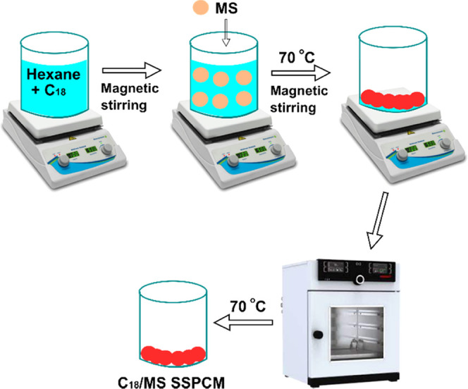
Scheme of the preparation of C18/MS SSPCMs.
4.3. Characterization Methods
The morphology was examined using field emission scanning electron microscopy (FE-SEM) with a FE-SEM S4800 instrument (Hitachi, Japan). The porosities were evaluated with nitrogen adsorption–desorption isotherms, using a BELSORP–Max instrument (MicrotracBel, Japan) at the temperature of liquid nitrogen (−196 °C). The surface area was calculated based on the Brunauer–Emmett–Teller (BET) method. The pore size distribution was estimated by the nonlocal density functional theory (NLDFT). The mesopore volume was calculated at a P/P0 of 0.95. The chemical compositions were examined with Fourier transform infrared spectroscopy using a Nicolet 6700 FT-IR instrument (Thermo Scientific, USA) in a wavenumber range of 400–4000 cm–1.
The thermal characteristics were studied with differential scanning calorimetry, using a DSC 4000 instrument (Perkin Elmer, USA). The measurements were conducted in the temperature range of 0–45 °C at a ramp rate of 10 °C/min and with 20 mL/min N2 purge gas. The phase change temperature of the materials was regarded as the onset temperature in DSC curves. DSC measurement was conducted every two cycles, and the second one was used for discussion and calculation. The crystallization properties were examined with powder X-ray diffraction, using a Rigaku Miniflex instrument (Japan) with Cu–Kα radiation. The measurements were conducted at a current of 15 mA, voltage of 40 kVe, and a scanning rate of 5°/min in a 2θ range of 5–50°.
The leakage resistance test was performed as follows. Approximately, 5 g of the prepared materials was compressed into a round block with dimensions of 30 mm × 10 nm using a homemade mold and compressor. The round block was placed on filter paper and kept in an oven for 60 min at 60 °C. Subsequently, the round block was taken off the filter paper and observed for possible leakage. The thermal stability was examined by thermogravimetric analysis, using a TGA 4000 instrument (Perkin Elmer, USA). The measurements were conducted at a temperature range of 30–500 °C, at a ramp rate of 10 °C/min, and with 20 mL/min N2 purge gas.
The thermal performance evaluation of the prepared C18/MS SSPCM in building materials was tested with an apparatus illustrated in Figure 11. A prepared C18/MS SSPCM with 70 wt % C18 was thoroughly mixed with gypsum at two contents of 10 and 20 wt % SSPCM to form SSPCM-incorporated gypsums. The selected material (∼15 g) was compressed in a cylindrical storage unit (30 mm × 150 mm). A thermocouple (T-type) and a data acquisition unit (MV200, Yokogawa Electric Corporation, Japan) were used to record the temperature change during the tests. The storage unit was first placed in a low-temperature oil bath (2 °C) until the temperature was stabilized. Then, the storage unit was rapidly moved to a high-temperature oil bath (50 °C), and the temperature change during heat storage (melting) was monitored. When the unit reached a stable temperature at nearly 50 °C, it was rapidly moved to the low-temperature oil bath and the temperature change during heat release (solidification) was recorded.
Figure 11.
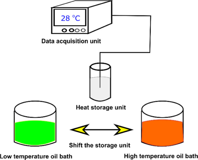
Illustration of the apparatus for the thermal performance evaluation test.
Acknowledgments
This research is supported by the Ho Chi Minh City University of Technology and Education, Vietnam.
The authors declare no competing financial interest.
References
- Cabeza L. F.; Castell A.; Barreneche C.; de Gracia A.; Fernández A. I. Materials used as PCM in thermal energy storage in buildings: A review. Renewable Sustainable Energy Rev. 2011, 15, 1675–1695. 10.1016/j.rser.2010.11.018. [DOI] [Google Scholar]
- Zhou D.; Zhao C. Y.; Tian Y. Review on thermal energy storage with phase change materials (PCMs) in building applications. Appl. Energy 2012, 92, 593–605. 10.1016/j.apenergy.2011.08.025. [DOI] [Google Scholar]
- Gao H.; Wang J.; Chen X.; Wang G.; Huang X.; Li A.; Dong W. Nanoconfinement effects on thermal properties of nanoporous shape-stabilized composite PCMs: A review. Nano Energy 2018, 53, 769–797. 10.1016/j.nanoen.2018.09.007. [DOI] [Google Scholar]
- Drissi S.; Ling T.-C.; Mo K. H.; Eddhahak A. A review of microencapsulated and composite phase change materials: Alteration of strength and thermal properties of cement-based materials. Renewable Sustainable Energy Rev. 2019, 110, 467–484. 10.1016/j.rser.2019.04.072. [DOI] [Google Scholar]
- Liu Z.; Yu Z.; Yang T.; Qin D.; Li S.; Zhang G.; Haghighat F.; Joybari M. M. A review on macro-encapsulated phase change material for building envelope applications. Build. Environ. 2018, 144, 281–294. 10.1016/j.buildenv.2018.08.030. [DOI] [Google Scholar]
- Nguyen G. T.; Hwang H. S.; Lee J.; Cha D. A.; Park I. n-Octadecane/Fumed Silica Phase Change Composite as Building Envelope for High Energy Efficiency. Nanomaterials 2021, 11, 566. 10.3390/nano11030566. [DOI] [PMC free article] [PubMed] [Google Scholar]
- Li C.; Yu H.; Song Y.; Wang M.; Liu Z. A n-octadecane/hierarchically porous TiO2 form-stable PCM for thermal energy storage. Renewable Energy 2020, 145, 1465–1473. 10.1016/j.renene.2019.06.070. [DOI] [Google Scholar]
- Kang Y.; Jeong S.-G.; Wi S.; Kim S. Energy efficient Bio-based PCM with silica fume composites to apply in concrete for energy saving in buildings. Sol. Energy Mater. Sol. Cells 2015, 143, 430–434. 10.1016/j.solmat.2015.07.026. [DOI] [Google Scholar]
- Veerakumar C.; Sreekumar A. Thermo-physical investigation and experimental discharge characteristics of lauryl alcohol as a potential phase change material for thermal management in buildings. Renewable Energy 2020, 148, 492–503. 10.1016/j.renene.2019.10.055. [DOI] [Google Scholar]
- Fu L.; Wang Q.; Ye R.; Fang X.; Zhang Z. A calcium chloride hexahydrate/expanded perlite composite with good heat storage and insulation properties for building energy conservation. Renewable Energy 2017, 114, 733–743. 10.1016/j.renene.2017.07.091. [DOI] [Google Scholar]
- Li C.; Zhang B.; Xie B.; Zhao X.; Chen J. Tailored phase change behavior of Na2SO4·10H2O/expanded graphite composite for thermal energy storage. Energy Convers. Manage. 2020, 208, 112586 10.1016/j.enconman.2020.112586. [DOI] [Google Scholar]
- Chen W.; Liang X.; Wang S.; Gao X.; Zhang Z.; Fang Y. Polyurethane macro-encapsulation for CH3COONa·3H2O-Na2S2O3·5H2O/Melamine sponge to fabricate form-stable composite phase change material. Chem. Eng. J. 2021, 410, 128308 10.1016/j.cej.2020.128308. [DOI] [Google Scholar]
- Chen W.; Liang X.; Wang S.; Ding Y.; Gao X.; Zhang Z.; Fang Y. SiO2 hydrophilic modification of expanded graphite to fabricate form-stable ternary nitrate composite room temperature phase change material for thermal energy storage. Chem. Eng. J. 2021, 413, 127549 10.1016/j.cej.2020.127549. [DOI] [Google Scholar]
- Shahid U. B.; Abdala A. A critical review of phase change material composite performance through Figure-of-Merit analysis: Graphene vs Boron Nitride. Energy Storage Mater. 2021, 34, 365–387. 10.1016/j.ensm.2020.10.004. [DOI] [Google Scholar]
- Zhang K.; Wang J.; Xu L.; Xie H.; Guo Z. Preparation and thermal characterization of n-octadecane/pentafluorostyrene nanocapsules for phase-change energy storage. J. Energy Storage 2021, 35, 102327 10.1016/j.est.2021.102327. [DOI] [Google Scholar]
- Qian T.; Li J. Octadecane/C-decorated diatomite composite phase change material with enhanced thermal conductivity as aggregate for developing structural–functional integrated cement for thermal energy storage. Energy 2018, 142, 234–249. 10.1016/j.energy.2017.10.021. [DOI] [Google Scholar]
- Jeong S.-G.; Jeon J.; Cha J.; Kim J.; Kim S. Preparation and evaluation of thermal enhanced silica fume by incorporating organic PCM, for application to concrete. Energy Build. 2013, 62, 190–195. 10.1016/j.enbuild.2013.02.053. [DOI] [Google Scholar]
- Mitran R. A.; Berger D.; Munteanu C.; Matei C. Evaluation of Different Mesoporous Silica Supports for Energy Storage in Shape-Stabilized Phase Change Materials with Dual Thermal Responses. J. Phys. Chem. A 2015, 119, 15177–15184. 10.1021/acs.jpcc.5b02608. [DOI] [Google Scholar]
- Liu H.; Qian Z.; Wang Q.; Wu D.; Wang X. Development of Renewable Biomass-Derived Carbonaceous Aerogel/Mannitol Phase-Change Composites for High Thermal-Energy-Release Efficiency and Shape Stabilization. ACS Appl. Energy Mater. 2021, 4, 1714–1730. 10.1021/acsaem.0c02864. [DOI] [Google Scholar]
- Tang J.; Yang M.; Yu F.; Chen X.; Tan L.; Wang G. 1-Octadecanol@hierarchical porous polymer composite as a novel shape-stability phase change material for latent heat thermal energy storage. Appl. Energy 2017, 187, 514–522. 10.1016/j.apenergy.2016.11.043. [DOI] [Google Scholar]
- Chen W.; Liang X.; Han W.; Wang S.; Gao X.; Zhang Z.; Fang Y. 3D shape-stable temperature-regulated macro-encapsulated phase change material: KAl(SO4)2·12H2O-C2H2O4·2H2O-CO(NH2)2 eutectic/polyurethane foam as core and carbon modified silicone resin as shell. J. Mater. Sci. Technol. 2022, 100, 27–35. 10.1016/j.jmst.2021.06.006. [DOI] [Google Scholar]
- Qu Z. G.; Li W. Q.; Wang J. L.; Tao W. Q. Passive thermal management using metal foam saturated with phase change material in a heat sink. Int. Commun. Heat Mass Transfer 2012, 39, 1546–1549. 10.1016/j.icheatmasstransfer.2012.09.001. [DOI] [Google Scholar]
- Min X.; Fang M.; Huang Z.; Liu Yg.; Huang Y.; Wen R.; Qian T.; Wu X. Enhanced thermal properties of novel shape-stabilized PEG composite phase change materials with radial mesoporous silica sphere for thermal energy storage. Sci. Rep. 2015, 5, 12964 10.1038/srep12964. [DOI] [PMC free article] [PubMed] [Google Scholar]
- Chen D.; Chen Y.; Guo X.; Tao W.; Wang J.; Gao S.; Gao J. Mesoporous silica nanoparticles with wrinkled structure as the matrix of myristic acid for the preparation of a promising new shape-stabilized phase change material via simple method. RSC Adv. 2018, 8, 34224–34231. 10.1039/C8RA06536E. [DOI] [PMC free article] [PubMed] [Google Scholar]
- Nomura T.; Zhu C.; Sheng N.; Tabuchi K.; Sagara A.; Akiyama T. Shape-stabilized phase change composite by impregnation of octadecane into mesoporous SiO2. Sol. Energy Mater. Sol. Cells 2015, 143, 424–429. 10.1016/j.solmat.2015.07.028. [DOI] [Google Scholar]
- Al-Oweini R.; El-Rassy H. Synthesis and characterization by FTIR spectroscopy of silica aerogels prepared using several Si(OR)4 and R″Si(OR′)3 precursors. J. Mol. Struct. 2009, 919, 140–145. 10.1016/j.molstruc.2008.08.025. [DOI] [Google Scholar]
- Krycka K. L.; Dura J. A.; Langston L. J.; Burba C. M. Nanoconfinement-Induced Phase Segregation of Binary Benzene–Cyclohexane Solutions within a Chemically Inert Matrix. J. Phys. Chem. A 2018, 122, 7676–7684. 10.1021/acs.jpcc.7b11365. [DOI] [Google Scholar]
- Du X.; Wang S.; Du Z.; Cheng X.; Wang H. Preparation and characterization of flame-retardant nanoencapsulated phase change materials with poly(methylmethacrylate) shells for thermal energy storage. J. Mater. Chem. A 2018, 6, 17519–17529. 10.1039/C8TA07086E. [DOI] [Google Scholar]
- Qian T.; Li J.; Min X.; Fan B. Integration of Pore Confinement and Hydrogen-Bond Influence on the Crystallization Behavior of C18 PCMs in Mesoporous Silica for Form-Stable Phase Change Materials. ACS Sustainable Chem. Eng. 2018, 6, 897–908. 10.1021/acssuschemeng.7b03267. [DOI] [Google Scholar]
- Gao J.; Zhou J.; Zhang X.; Shi Q.; Han Z.; Chen Y. Facile functionalized mesoporous silica using biomimetic method as new matrix for preparation of shape-stabilized phase-change material with improved enthalpy. Int. J. Energy Res. 2019, 3, 8649–8659. 10.1002/er.4861. [DOI] [Google Scholar]
- Wang L.; Kong X.; Ren J.; Fan M.; Li H. Novel hybrid composite phase change materials with high thermal performance based on aluminium nitride and nanocapsules. Energy 2022, 238, 121775 10.1016/j.energy.2021.121775. [DOI] [Google Scholar]
- Zhang Z.; Liu Y.; Wang J.; Sun L.; Xie T.; Yang K.; Li Z. Preparation and characterization of high efficiency microencapsulated phase change material based on paraffin wax core and SiO2 shell derived from sodium silicate precursor. Colloids Surf., A 2021, 625, 126905 10.1016/j.colsurfa.2021.126905. [DOI] [Google Scholar]
- Zhu Y.; Qin Y.; Liang S.; Chen K.; Tian C.; Wang J.; Luo X.; Zhang L. Graphene/SiO2/n-octadecane nanoencapsulated phase change material with flower like morphology, high thermal conductivity, and suppressed supercooling. Appl. Energy 2019, 250, 98–108. 10.1016/j.apenergy.2019.05.021. [DOI] [Google Scholar]
- Liu Z.; Jiang L.; Fu X.; Zhang J.; Lei J. Preparation and characterization of n-octadecane-based reversible gel as form-stable phase change materials for thermal energy storage. J. Therm. Anal. Calorim. 2020, 140, 2159–2170. 10.1007/s10973-019-08975-2. [DOI] [Google Scholar]
- Mert H. H.; Mert M. S. Design of n-octadecane-based form-stable composite phase change materials embedded in porous nano alumina for thermal energy storage applications. J. Therm. Anal. Calorim. 2021, 147, 4925–4934. [Google Scholar]
- Kim S.; Paek S.; Jeong S.-G.; Lee J.-H.; Kim S. Thermal performance enhancement of mortar mixed with octadecane/xGnP SSPCM to save building energy consumption. Sol. Energy Mater. Sol. Cells 2014, 122, 257–263. 10.1016/j.solmat.2013.12.015. [DOI] [Google Scholar]
- Wang J.; Yang M.; Lu Y.; Jin Z.; Tan L.; Gao H.; Fan S.; Dong W.; Wang G. Surface functionalization engineering driven crystallization behavior of polyethylene glycol confined in mesoporous silica for shape-stabilized phase change materials. Nano Energy 2016, 19, 78–87. 10.1016/j.nanoen.2015.11.001. [DOI] [Google Scholar]