

Abstract
Porous architecture in bone substitutes, notably the interconnectivity of pores, is a critical factor for bone ingrowth. However, controlling the pore interconnectivity while maintaining the microarchitecture has not yet been achieved using conventional methods, such as sintering. Herein, we fabricated a porous block using the crystal growth of calcium sulfate dihydrate, and controlled the pore interconnectivity by limiting the region of crystal growth. The calcium sulfate dihydrate blocks were transformed to bone apatite, carbonate apatite (CO3Ap) through dissolution–precipitation reactions. Thus, CO3Ap blocks with 15% and 30% interconnected pore volumes were obtained while maintaining the microarchitecture: they were designated as CO3Ap-15 and CO3Ap-30, respectively. At 4 weeks after implantation in a rabbit femur defect, new bone formed throughout CO3Ap-30, whereas little bone was formed in the center region of CO3Ap-15. At 12 weeks after implantation, a large portion of CO3Ap-30 was replaced with new bone and the boundary with the host bone became blurred. In contrast, CO3Ap-15 remained in the defect and the boundary with the host bone was still clear. Thus, the interconnected pores promote bone ingrowth, followed by replacement of the material with new bone. These findings provide a useful guide for designing bone substitutes for rapid bone regeneration.
Keywords: bone substitutes, carbonate apatite, pore interconnectivity, bone regeneration
Introduction
Bone defects resulting from severe trauma or wide resection of bone tumors require a graft material for their reconstruction [1–4]. Autografts using the iliac crest, fibula or resected bone after devitalization have been used as an effective option [1, 2, 4]. Although autografting is still regarded as the gold standard for bone reconstruction in post-traumatic conditions [1–3], problems, such as limited tissue mass availability, risk of infection and increased morbidity of the donor site, are unavoidable [5–7]. Therefore, the development of effective bone-substitute materials is urgently needed.
The outcome of bone reconstruction is primarily determined by the chemical composition of the grafting material [8, 9]. Among the bone-substitute materials currently used, carbonate apatite (CO3Ap), which is the main component of the bone mineral [10–12], has recently attracted much attention owing to its ability to be replaced by new bone during the bone remodeling process, as observed in autografts [13–15]. A much higher osteoconductivity of CO3Ap was also reported as compared with those of sintered hydroxyapatite (HAp) and β-tricalcium phosphate [16–22].
The architecture of the bone substitutes is also a factor that significantly affects the outcome of bone regeneration [23]. In particular, porous architectures that increase their specific surface area and vascular permeability are considered essential for the success of reconstruction [23–25]. Although the pore size and volume of the materials typically affect bone ingrowth and formation [26–32], the pore geometry, such as uniformity, orientation and interconnectivity, is also a key design consideration. Notably, an interconnected architecture of pores has been considered effective for the penetration of body fluids and cells, contributing to bone ingrowth. Although the introduction of interconnected pores [2, 23, 33–35] and/or continuous channels [29, 30, 36–40] has been achieved, controlling the pore interconnectivity while maintaining the microarchitecture has not been realized by conventional methods, such as sintering.
Interconnected porous blocks can be fabricated by interconnecting the granules and creating gaps between them. However, in the case of CO3Ap, the direct interconnection of CO3Ap granules is difficult because they have no setting ability and sinterability below the decomposition temperature. Therefore, we previously fabricated interconnected porous CO3Ap blocks by interconnecting precursor granules followed by compositional transformation to CO3Ap through a dissolution–precipitation reaction; they were interconnected by a thermal fusion with an organic binder [41], the hydrate expansion of CaO granules [42], the setting reaction of α-tricalcium phosphate spheres [43] and the setting reaction of calcium sulfate hemihydrate (CaSO4·1/2H2O) granules [44]. The setting reaction of CaSO4·1/2H2O granules with water occurs with highly aggressive crystal growth of calcium sulfate dihydrate (CaSO4·2H2O). Although this crystal growth easily causes clogging of gaps between granules and spoiling of the pore interconnectivity of CaSO4·2H2O, we found that this clogging could be avoided by regulating the amount of water [44]. In other words, the pore interconnectivity of the CO3Ap blocks might be adjustable based on this water removal process.
In this study, we aimed to fabricate CO3Ap blocks with different pore interconnectivities while maintaining the microarchitecture for histological evaluation. The pore interconnectivity was controlled by limiting the region of crystal growth of CaSO4·2H2O during the setting reaction. Centrifugal force was used to partially remove water and limit the region of crystal growth. After converting the CaSO4·2H2O blocks to CO3Ap through dissolution–precipitation reactions, we implanted the CO3Ap blocks in the rabbit femur defect to evaluate the influence of pore interconnectivity on bone ingrowth, new bone formation and material resorption.
Materials and methods
Fabrication of CO3Ap block
In our previous study, a porous CO3Ap block was fabricated through dissolution–precipitation reactions of a porous calcium sulfate anhydrous (CaSO4) block, which was obtained by the setting reaction of CaSO4·1/2H2O granules with water followed by dehydration heat treatment [44]. In this study, we fabricated CO3Ap blocks with different pore interconnectivities based on this method, with slight modifications.
In brief, commercial CaSO4·1/2H2O powder (NEW FUJIROCK WHITE, improved dental stone powder, GC Corporation, Tokyo, Japan) was mixed with distilled water at a liquid to powder ratio of 0.2 cm3·g−1 to obtain a set CaSO4·2H2O block, followed by granulating into the size of 100–200 µm and dehydrating at 120°C for 24 h. The CaSO4·1/2H2O granules obtained were placed in an acrylic mold (φ 6 mm × 9 mm) with covered stainless steel meshes. Two wetting conditions were used to control the pore interconnectivity: the packed granules were immersed in distilled water for 30 s followed by centrifugation at a speed of 500× g for 3 min using a tabletop centrifuge (Model 2420, Kubota, Tokyo, Japan), or immersed in distilled water for 30 s without centrifugation. This centrifuge process was designed to remove water except for that retained by interfacial tension with the granules. Both samples were kept inside the mold at room temperature for 24 h to prepare porous CaSO4·2H2O blocks. The blocks obtained were heat-treated at a heating rate of 1°C·min−1–750°C and maintained at 750°C for 6 h. After cooling to room temperature, the blocks were immersed in a 1 mol·dm−3 solution of Na2CO3 (Fuji Film Wako Pure Chemical Corporation, Osaka, Japan) at 60°C for 3 days to convert CaSO4 into calcium carbonate (CaCO3). The CaCO3 blocks obtained were immersed in a 0.1 mol·dm−3 solution of Na2HPO4 (Fuji Film Wako Pure Chemical Corporation) at 60°C for compositional transformation to CO3Ap. The CO3Ap blocks obtained from the CaSO4·2H2O block centrifuged at 500× g for water removal and those without centrifugation had 30% and 15% interconnected pore volumes, respectively, as shown in the Results and discussion section. Hence, the CO3Ap blocks derived from the CaSO4·2H2O block centrifuged at 500× g and those without centrifugation are referred to as CO3Ap-30 and CO3Ap-15, respectively. The compositional transformation from CaCO3 to CO3Ap in a Na2HPO4 solution was conducted for 7 (CO3Ap-30) or 14 days (CO3Ap-15).
Characterization
The crystal phases of the CO3Ap blocks were analyzed by powder X-ray diffraction (XRD; D8 Advance diffractometer, Bruker AXS GmbH, Karlsruhe, Germany) with CuKα radiation generated at an acceleration voltage of 40 kV and a current of 40 mA. The chemical characteristics of the CO3Ap blocks were analyzed by Fourier transform infrared (FTIR) spectroscopy (FT/IR-6200, JASCO, Tokyo, Japan) using the KBr disk method. The carbonate content in the CO3Ap blocks was determined by performing the elemental carbon–hydrogen–nitrogen (CHN) analysis (MT-6, Yanako Analytical Instruments, Kyoto, Japan). The remaining sulfate content in the CO3Ap blocks was assessed by inductively coupled plasma–optical emission spectrometry (ICP-OES, Optima 7300 DV, PerkinElmer, MA, USA).
The surface morphologies of the CO3Ap blocks were investigated by scanning electron microscopy (SEM; S-3400N, Hitachi High Technologies, Tokyo, Japan) with an acceleration voltage of 10 kV, after being coated with gold-palladium using a magnetron sputtering machine (MSP-1S, Vacuum Device Co., Ibaraki, Japan). Elemental analysis on the fractured surface of the samples was performed by energy-dispersive X-ray (EDX) spectroscopy coupled with the SEM with an accelerating voltage of 15 kV. The volume and size distribution of the interconnected pores in the CO3Ap blocks were analyzed using mercury intrusion porosimetry (AutoPore 9420, Shimadzu Corporation, Kyoto, Japan). The internal morphology of the CO3Ap blocks was investigated using the micro-computed tomography (μ-CT) scanning (ScanXmate-L090T, Comscan, Kanagawa, Japan).
The penetrability of the CO3Ap blocks was evaluated by the infiltration of a 0.05% toluidine blue solution (Fuji Film Wako Pure Chemical Corporation). The block was then immersed in the dye solution for 3 min. The dyed blocks were dried at 60°C for 1 h.
The mechanical strength of the CO3Ap blocks was evaluated in terms of the compressive strength and diametral tensile strength. After the diameter and height of each block were measured with a micrometer (IP65, Mitutoyo Co., Ltd, Kanagawa, Japan), the block was crushed by a loaded force at a crosshead speed of 1 mm/min using a universal testing machine (Autograph, AGS-J, Shimadzu Corporation). Eight samples per group were analyzed to determine the average compressive strength and diametral tensile strength. The total porosity of the CO3Ap blocks was determined from their bulk density (determined from each block’s weight and volume) and calculated using the theoretical density of HAp (3.16 g·cm−3). The apparent porosity of the CO3Ap blocks was determined according to Archimedes’ principle using water as the immersion liquid. Eight samples per group were analyzed to determine the average total porosity and apparent porosity.
The release profiles of calcium and phosphorus were investigated by immersing 100 mm3 of the CO3Ap blocks in 5000 mm3 of 4-(2-hydroxyethyl)-1-piperazineethanesulfonic acid (HEPES) buffer solution (Fuji Film Wako Pure Chemical Corporation) at 37°C. The amount of calcium and phosphorus released was determined by ICP-OES using Optima 7300 DV (PerkinElmer). The HEPES buffer solution was replaced with equal volume of fresh solution every seventh day.
In vitro evaluation
As described in our previous work [45], MC3T3-E1 cells (Riken BioResource Center, Ibaraki, Japan) were maintained in a cell culture medium, which was an alpha modification of Eagle’s minimum essential medium (α-MEM; Gibco, USA) supplemented with 10% fetal bovine serum (Gibco), 100 U·cm−3 penicillin, 100 mg·cm−3 streptomycin and 0.25 mg·cm−3 amphotericin B (Gibco). The cells were incubated at 37°C in a humidified atmosphere containing 5% CO2. For sample preparation for cell invasion assay, each CO3Ap block (φ 6 mm × 3 mm) was tightly inserted into the edge of an acrylic tube (φ 6 mm × 4 mm) to inhibit free migration of cells along the side of the block. The CO3Ap blocks inserted in the tubes were placed in a well plate so that one side of the block and tube were in contact with the bottom of the plate. All samples were sterilized in 70% ethanol and rinsed with phosphate buffered saline (PBS). All sterilized samples were immersed in the medium for 1 day to prevent the burst release of calcium ions.
In cell invasion assay, MC3T3-E1 cells were seeded on the samples at an approximate initial concentration of 5.5 × 10⁴ cells·cm−3. After 7 days of incubation, the cells attached to the samples were rinsed with PBS and fixed with 4% paraformaldehyde for 15 min. For SEM observation, the cells were dehydrated in a graded ethanol series consisting of 50%, 60%, 70%, 80%, 90% and 99.5% ethanol, and dried by hexamethyldisilazane (Fuji Film Wako Pure Chemical Corporation) before being coated with gold–palladium. For fluorescence staining, the attached cells were permeabilized by immersing the samples in 0.5% Triton X-100 for 15 min. The non-specific reactions were blocked by 60 min of immersion in PBS containing 3% bovine serum albumin at room temperature. F-actins and nuclei of the attached cells were stained with Acti-stain 555 phalloidin (Cytoskeleton Inc., Denver, USA) and Hoechst 33342 (Dojindo, Kumamoto, Japan), respectively. Fluorescence images were captured from the bottom of the samples.
In vivo evaluation
The animal experiments conducted in this study were approved by the Animal Care and Use Committee of Kyushu University (No. A30-293-0; issued 26 November 2018). Eighteen week-old male Japanese white rabbits (Japan SLC, Inc., Shizuoka, Japan) weighing 3.0–3.5 kg were utilized for the experiments. These rabbits were housed at the Center of Biomedical Research, Research Center for Human Disease Modeling, Graduate School of Medical Sciences, Kyushu University. They were maintained on a standard feed and water.
For sample implantation, the rabbits were initially anesthetized via intraperitoneal injection of a mixture of ketamine (30 mg·kg−1) and xylazine (5.0 mg·kg−1). The rear limbs were shaved to remove the fur, and then the skin was disinfected with 10% povidone-iodine (Meiji Seika Pharma Co., Ltd, Tokyo, Japan). The distal epiphysis of the femur was selected as the implant site because of its sufficient bone volume. An incision was made in the skin and periosteum of the femur, and a cylindrical defect (φ 6 mm × 3 mm) was created using a trephine bur. This defect size was adopted based on previous studies [40, 42], in which an effective comparison of material architecture of CO3Ap was made within 12 weeks without perforating into bone marrow region. It can be noted that this defect size is not generally regarded critical and may not be used for long-term experiments. CO3Ap-30 or CO3Ap-15 was implanted into the bone defect, and the periosteum and skin flap were closed (n = 3 per group). The rabbits were allowed unrestrained movement in their cages after they recovery from anesthesia. After implantation for 4 and 12 weeks, the rabbits were sacrificed, and the specimens were removed.
The μ-CT images of the specimens were obtained using a μ-CT scanner (SkyScan, Bruker Corporation, MA, USA). For histomorphometric analyses, the specimens were fixed in 10% formalin neutral buffer solution, decalcified with 0.5 mol·dm−3 ethylenediaminetetraacetic acid, and embedded in paraffin. The paraffin blocks were sliced at 3-μm thickness using a sliding microtome (REM-710/CBUH, Yamato Kohki, Asaka, Japan). After deparaffinization, hematoxylin and eosin (HE) staining was performed using a general protocol.
Statistical analysis
Statistical analyses were performed by Tukey’s test after one-way ANOVA using R software (The R Foundation for Statistical Computing, ver. 4.0.0, 2020). P < 0.05 was considered statistically significant.
Results and discussion
Fabrication and characterization of CO3Ap blocks
The CO3Ap blocks derived from the CaSO4·2H2O blocks centrifuged at 500× g for water removal during the setting reaction (CO3Ap-30) and those without centrifugation processes (CO3Ap-15) showed the same XRD patterns, confirming that both were purely composed of apatite without remaining precursors, such as CaSO4 and CaCO3 (Fig. 1A). The remaining sulfate groups were not detected from ICP-OES. Furthermore, the FTIR spectra confirmed the presence of carbonate groups and the absence of hydroxyl groups (Fig. 1B). The absorption peaks detected at 1470 and 1420 cm−1 correspond to the substitution of hydroxyl and phosphate groups by carbonate groups (Fig. 1B). Therefore, the apatites obtained were both AB-type CO3Ap. The CHN analyses showed no significant differences in carbonate content between CO3Ap-30 and CO3Ap-15 (Table 1). The carbonate content is equal to that of human bone apatite (6–9 wt%) [12–14].
Figure 1.

(A) XRD patterns and (B) FTIR spectra of CO3Ap-30, CO3Ap-15 and standard HAp. The miller indices of HAp were assigned from PDF# 00-009-0432.
Table 1.
Carbonate content of CO3Ap blocks
| Sample | Carbonate content (wt%) |
|---|---|
| CO3Ap-30 | 7.5 ± 0.5 |
| CO3Ap-15 | 7.2 ± 0.2 |
Both CO3Ap blocks were cylindrical blocks constructed of granules (Fig. 2A–D). The 2D-sliced images showed a significant difference in the internal architecture (Fig. 2E–H). CO3Ap-30 showed a pore-interconnected structure throughout the sliced images (Fig. 2E and G). In contrast, CO3Ap-15 showed less continuous pore interconnections (Fig. 2F and H). The SEM images of the two groups showed a significant difference in surface morphology (Fig. 2I and J). The surface of CO3Ap-30 exhibited a clear bridging structure of granules (Fig. 2I), while the bridging pattern was smeared out on the surface of CO3Ap-15 (Fig. 2J). Both CO3Ap blocks were composed of rod-like crystals (Fig. 2K and L). The surface morphologies observed were consistent with those of CaSO4·2H2O blocks, which showed a similar pattern of granular bridging depending on the water removal process (Supplementary Fig. S1). Therefore, the multi-step compositional transformation of the blocks from CaSO4·2H2O to CO3Ap did not alter the macroscopic morphology. The structural difference between CO3Ap-30 and CO3Ap-15 is likely to reflect the difference in the crystal growth of CaSO4·2H2O. Although the crystal growth of CaSO4·2H2O causes expansion in general, free expansion was restricted at the area contacting with the wall of the mold used for filling CaSO4·1/2H2O granules. This restricted expansion resulted in a densified structure at the periphery of CaSO4·2H2O blocks and CO3Ap blocks (Fig. 2E–H), as also confirmed by a porosimetry along the diametral direction based on μ-CT images (Supplementary Fig. S2). This densification was more significantly observed in CO3Ap-15, where much crystal growth occurred. Despite this porosity gradient, the composition of both CO3Ap blocks was uniform from the outer edge to the central region, as confirmed by EDX analysis (Supplementary Fig. S3).
Figure 2.

Photograph images of (A) CO3Ap-30 and (B) CO3Ap-15. μ-CT scanning observations of materials. μ-CT-based 3D reconstruction images of (C) CO3Ap-30 and (D) CO3Ap-15. μ-CT-based sliced images at a sagittal section of (E) CO3Ap-30 and (F) CO3Ap-15. μ-CT-based sliced images at a transverse section of (G) CO3Ap-30 and (H) CO3Ap-15. SEM images of (I) CO3Ap-30 and (J) CO3Ap-15. Magnified SEM images of (K) CO3Ap-30 and (L) CO3Ap-15.
To find quantitative differences in the interconnected porous architecture between CO3Ap-30 and CO3Ap-15, mercury intrusion porosimetry was employed (Fig. 3). CO3Ap-30 showed a larger interconnected pore volume than CO3Ap-15 (Fig. 3A). Both the CO3Ap blocks had a pore size distribution at two different scales, namely, larger pores of ∼29 μm (CO3Ap-30) or 14 μm (CO3Ap-15) and smaller pores of ∼1 μm in diameter (Fig. 3B). These larger and smaller pores are likely to originate in the intergranular and intercrystalline gaps of CO3Ap, respectively. By computing the peak areas of larger pores, the interconnected pore volumes in CO3Ap-30 and CO3Ap-15 were determined as 280 and 130 mm3·g−1, respectively. These pore volumes (280 and 130 mm3·g−1) correspond to 30% and 15% of the total volume, respectively.
Figure 3.

(A) Cumulative and (B) differential pore volume plotted as a function of pore diameter of CO3Ap-30 and CO3Ap-15. Differential pattern was best-fitted by two Lorentzian functions.
Pore interconnectivity was visualized using a dye penetration assay (Fig. 4). Complete dye penetration was observed in CO3Ap-30 showing a stained cross-section, whereas the assay of CO3Ap-15 resulted in a limited stained area, indicating full and partial pore interconnectivity of CO3Ap-30 and CO3Ap-15, respectively. This observation coincides with our previous study, in which the water removal process was identified as the key to creating interconnected pores [44].
Figure 4.

Photograph images of materials after dye penetration assay. Perspective views of (A) CO3Ap-30 and (B) CO3Ap-15. Cross-sectional views of (C) CO3Ap-30 and (D) CO3Ap-15.
There was no significant difference in the mechanical strength and total porosity between CO3Ap-30 and CO3Ap-15 (Fig. 5A–C). In other words, the improved pore interconnectivity did not affect the mechanical strength in accordance with the maintained total porosity. Since the equal amount of the starting substance, CaSO4·1/2H2O granules were used, both CO3Ap-30 and CO3Ap-15 were obtained from the same amount of calcium, resulting in the equal total porosity. In contrast, the apparent porosity of CO3Ap-30 determined by the Archimedes method was significantly higher than that of CO3Ap-15, confirming the increased interconnected pores and the reduced closed pores (Fig. 5D). At present, the mechanism necessary to yield an equal mechanical strength while having different pore interconnectivity has not been fully clarified. The mechanical strength is thought to depend mainly on the interlocking degree of CO3Ap crystals. Although CO3Ap-30 had a fractured surface with clear granules-fused structure, CO3Ap-15 exhibited a more disordered fractured surface (Supplementary Fig. S3). Therefore, the CO3Ap crystals may be also interlocked at the interstitial gaps between granules as well as the intergranular regions, when the crystal growth is prominent. These two contributions to the mechanical strength may result in an equal mechanical strength with an equal total porosity.
Figure 5.

(A) Compressive strength, (B) diametral tensile strength, (C) total porosity and (D) apparent porosity of CO3Ap-30 and CO3Ap-15. *P < 0.05.
The in vitro behaviors of the CO3Ap blocks were investigated in terms of ion release and cell invasion. During the 28 days of immersion in HEPES buffer, both CO3Ap-30 and CO3Ap-15 tended to constantly release calcium and phosphate ions at nearly equivalent rates (Fig. 6). This is consistent with the nearly equal specific surface areas, which were estimated from mercury intrusion porosimetry (CO3Ap-30: 1.79 m2·g−1; CO3Ap-15: 1.73 m2·g−1). After 7 days of cell culture, the cells tended to grow preferentially on the top of CO3Ap-15 surface rather than CO3Ap-30 surface (Fig. 7A and B). In contrast, no cells were found inside and on the bottom of CO3Ap-15, while CO3Ap-30 allowed cells to invade to a depth of 3 mm (Fig. 7C–J). Therefore, the difference in pore interconnectivity affected penetration of cells as well as body fluid.
Figure 6.

The amount of (A) calcium and (B) phosphorus released from CO3Ap-30 (black circles) and CO3Ap-15 (gray diamonds) to the HEPES buffer during 28 days of immersion measured using ICP-OES. *P < 0.05.
Figure 7.

Cell invasion assay of the samples with 3-mm thickness for 7 days of culture period. SEM images at the cell-seeded on-top surface of (A) CO3Ap-30 and (B) CO3Ap-15. SEM images at a cross-section of (C) CO3Ap-30 and (D) CO3Ap-15. SEM images at the bottom surface of (E) CO3Ap-30 and (F) CO3Ap-15. F-actins (red) and nuclei (blue) of attached cells on the bottom surface of (G) CO3Ap-30 and (H) CO3Ap-15. Magnified fluorescence images of the bottom surface of (I) CO3Ap-30 and (J) CO3Ap-15. Yellow triangles indicate cells.
In vivo evaluation
The above characterization of CO3Ap-30 and CO3Ap-15 demonstrated that only the pore interconnectivity was distinctly different between the two groups, whereas the chemical composition, micropore distribution, mechanical strength and total porosity were equal. Therefore, the comparison between CO3Ap-30 and CO3Ap-15 provides an effective evaluation of the effects associated with pore interconnectivity. Thus, both the CO3Ap blocks were implanted in a defect in the rabbit femur.
The μ-CT images showed that at 4 weeks after implantation, CO3Ap-30 and CO3Ap-15 remained in the bone defects and maintained their clear boundary with the host bone (Fig. 8A and B). CO3Ap-30 had a lower CT-positive value in the bone defect and a lower contrast with the host bone. At 12 weeks after implantation, the radiopacity of the defect area decreased in both groups, suggesting that the resorption of CO3Ap was progressed (Fig. 8C and D). This was accompanied by a diminished dense pattern of implant material, which had been observed during the 4-week period. In the case of CO3Ap-30 at the 12-week period, the CT-positive value in the defect was fairly close to that of the host bone (Fig. 8C). In other words, CO3Ap-30 had the potential to be resorbed and replaced by cancellous new bone in 12 weeks. In contrast, the remaining material area of CO3Ap-15 was clearly observed even at the 12-week period (Fig. 8D). Therefore, CO3Ap-15 was resorbed and replaced by new bone at a slower rate.
Figure 8.

μ-CT images of rabbit femurs with defects reconstructed by grafting CO3Ap-30 at (A) 4 weeks and (C) 12 weeks after implantation, and CO3Ap-15 at (B) 4 weeks and (D) 12 weeks after implantation
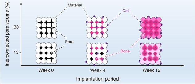
To investigate new bone formation, bone ingrowth and material resorption, histological analysis was performed with HE staining. At 4 weeks after implantation, both samples were continuously attached to the host bone without any fibrous tissue, confirming their histocompatibility and osteoconductivity (Fig. 9A and B). Moreover, new bone formed over the entire area inside CO3Ap-30, whereas the bone area inside CO3Ap-15 was limited to the region near the host bone. This indicates that interconnected pores in CO3Ap were easily occupied by new bone due to the absence of barriers for bone ingrowth, while closed pores prevent bone ingrowth into the center region of the material. Osteoblasts, osteoclasts and red blood cells were distributed inside the materials, indicating that the pores were effective for allowing cellular migration and providing an osteoconductive environment (Fig. 9C–H). Even in the area of limited bone formation in CO3Ap-15 (i.e. the center region), a large number of cells resided, which is thought to be due to the resorption of material by opening the pores that were initially not interconnected (Fig. 9D). Osteoblasts were aligned along the edge of the new bone, while osteoclasts were distributed around the material surfaces (Fig. 9E–H). At 12 weeks after implantation, CO3Ap-30 and CO3Ap-15 showed progressed resorption, as manifested in the reduced area of their building granules (Fig. 10A and B). As a morphological change, the CO3Ap-30-implanted area exhibited a trabecular bone-like pattern consisting of new bone and adipose tissue (Fig. 10A). The boundary between the CO3Ap-30-implanted area and the surrounding host bone became blurred, while the CO3Ap-15-implanted area was still clearly distinct from the host bone (Fig. 10A and B). Therefore, CO3Ap-30 was mostly replaced by cancellous-structured new bone in 12 weeks. In both groups, bone marrow-like tissue as well as adipose tissue was also observed (Fig. 10C and D). Therefore, migration or generation of soft tissue as well as hard tissue became pronounced upon progressed resorption of the material. These soft tissues may have migrated to the bone defect through the bone remodeling. Furthermore, mesenchymal and hematopoietic stem cells, which were thought to have differentiated mainly into osteoblasts and osteoclasts at the 4-week period, may have switched to adipocytes and myelocytes, respectively, to a certain extent. Osteoblasts in an array were observed at the interface between the bone and adipose tissue, while osteoclasts were mainly found near the remaining materials (Fig. 10E–H). Thus, the bone remodeling process governed by the osteoblastic new bone formation and osteoclastic resorption proceeded continuously during the implantation period.
Figure 9.

HE-Stained histological images of rabbit femurs with defects reconstructed by grafting (A) CO3Ap-30 and (B) CO3Ap-15 at 4 weeks after implantation. (C) and (D) show magnified versions of the images presented in (A) and (B), respectively. (E) and (F) show higher magnification images of typical regions in (A) and (B), respectively. (G) and (H) show TRAP-stained images in the region near (E) and (F), respectively. Yellow triangles, red triangles, blue triangles, ‘OB’, ‘OC’ and ‘#’denote new bone, red blood cells, adipose tissues, osteoblasts, osteoclasts and material, respectively.
Figure 10.

HE-Stained histological images of rabbit femurs with defects reconstructed by grafting (A) CO3Ap-30 and (B) CO3Ap-15 at 12 weeks after implantation. (C) and (D) show magnified versions of the images presented in (A) and (B), respectively. (E) and (F) show higher magnification images of typical regions in (A) and (B), respectively. (G) and (H) show TRAP-stained images in the region near (E) and (F), respectively. Yellow triangles, red triangles, blue triangles, ‘OB’, ‘OC’ and ‘#’denote new bone, red blood cells, adipose tissues, osteoblasts, osteoclasts and material, respectively.
The area percentages of bone and material in the bone defect were calculated from the histological sections (Fig. 11A and B). At 4 weeks after implantation, the bone area inside CO3Ap-30 was significantly larger than that inside CO3Ap-15 (Fig. 11A), corresponding to the observed difference in new bone formation in the region distant from the host bone (Fig. 9A and B). From Weeks 4–12, both groups showed an increase in the bone area, although this was not statistically significant in the case of CO3Ap-30 (Fig. 11A). Moreover, the material areas drastically decreased at 12 weeks after implantation (Fig. 11B), corresponding to the rapid resorption of CO3Ap- and replacement by cancellous-structured new bone (Figs 9 and 10).
Figure 11.

Area percentages of (A) bone and (B) remaining material in each bone defect. **P < 0.01.
The above in vivo evaluation clearly demonstrates that the interconnectivity of pores has a remarkable influence on new bone formation and material resorption, or CO3Ap-to-bone remodeling. The pore size of the CO3Ap blocks used in this study was smaller than that typically adopted. Considering that the pores smaller than 50 µm are usually referred to as micropores [32], both CO3Ap-30 and CO3Ap-15, which have larger pores distributed around 29 and 14 μm, respectively, should be referred to as microporous CO3Ap blocks. Nevertheless, these pores were liquid-penetrable (Fig. 4) and could be occupied by cells through bone ingrowth (Figs 9 and 10). Therefore, although quite small, the pores distributed around 29 and 14 μm acted as a penetrable space for bony tissue, similar to macropores. Typically, the effects of macropore size have been associated with angiogenesis, which is in competition with the ingrowth of fibrous tissue [28, 30]. Correspondingly, the osteoconductivity evaluated by the bone area decreased below a certain threshold of pore size (∼500 μm) [27]. From a geometrical point of view, osteoconductivity should also be affected by pore geometry, even at the same pore size and volume. For example, the lower threshold of the effective pore size was decreased to ∼300 μm by using a uniformly oriented honeycomb CO3Ap blocks [29, 30]. In this study, we used a CO3Ap block with fully interconnected pores smaller than 100 μm in diameter, and achieved almost complete replacement of the implanted material with new bone in 12 weeks (Fig. 10A, C and E). Therefore, 3D porous architectures with high pore interconnectivity are associated with rapid bone regeneration, which may drastically shorten hospitalization. Furthermore, upon significant resorption of the material, bone marrow-like tissues were observed at the 12-week period (Fig. 10). A detailed mechanism is currently not available. Similarly, a previous investigation using honeycombed CO3Ap reported the generation of bone marrow-like tissue upon progressed resorption of CO3Ap with a high micropore volume, which might be associated with an elevated local Ca2+ concentration [46]. As shown in the porosimetry results, both the CO3Ap blocks prepared in this study had a micropore volume of more than 50% of the pore volume (Fig. 3). Considering that even interconnected pores were smaller than 100 μm, the overall volume occupied by micropores was extremely large. Therefore, further studies are needed to understand the tissue reactions that generate bone marrow-like tissues using highly microporous architectures.
Conclusions
The CO3Ap blocks with 15% and 30% interconnected pore volumes, i.e. CO3Ap-15 and CO3Ap-30, for histological evaluation of the rabbit femur defect were fabricated in this study. Other structural parameters, such as microporosity, micropore size and total porosity, were equal between CO3Ap-15 and CO3Ap-30. The fabrication of CO3Ap-30 was achieved by a centrifuge method to limit the region of crystal growth of CaSO4·2H2O, followed by compositional transformation to CO3Ap. At the 4-week period, new bone formed over the entire region of CO3Ap-30, whereas a much more scarce formation of bone in the center region of CO3Ap-15 was observed. Therefore, the rate of bone ingrowth was significantly affected by the pore interconnectivity. At the 12-week period, the original block morphology of CO3Ap-30 mostly vanished upon replacement by cancellous-structured new bone, whereas CO3Ap-15 remained in the bone defect. From this observation, we conclude that introducing interconnected pores is a highly effective approach for realizing rapid bone regeneration by allowing earlier bone ingrowth, followed by replacement of the material with new bone.
Supplementary data
Supplementary data are available at REGBIO online.
Funding
This research was supported, in part, by Japan Agency for Medical Research and Development under Grant Number JP20im0502004, Grant-in-Aid for Research Activity start-up (18H06295) and Grant-in-Aid for Early-Career Scientists (20K18576) from Japan Society for the Promotion of Science.
Author contributions
M.E. carried out the preparation and characterization of materials, participated in the design of the study and analyzed in vivo experimental results; R.K. wrote the manuscript, conducted in vitro and in vivo experiments, carried out the characterization of materials and supervised the study; K.H. critically reviewed the manuscript and participated in the design of the study; A.T. participated in the design of the study; M.S. conducted in vitro experiments and critically reviewed the manuscript; K.I. conceived and designed the experiments, critically reviewed the manuscript and supervised the study.
Conflict of interest statement. None declared.
Supplementary Material
References
- 1. García-Gareta E, Coathup MJ, Blunn GW.. Osteoinduction of bone grafting materials for bone repair and regeneration. Bone 2015;81:112–21. [DOI] [PubMed] [Google Scholar]
- 2. Calori GM, Mazza E, Colombo M, Ripamonti C.. The use of bone-graft substitutes in large bone defects: any specific needs? Injury 2011;42:S56–63. [DOI] [PubMed] [Google Scholar]
- 3. Wang W, Yeung KW.. Bone grafts and biomaterials substitutes for bone defect repair: a review. Bioact Mater 2017;2:224–47. [DOI] [PMC free article] [PubMed] [Google Scholar]
- 4. Panagopoulos GN, Mavrogenis AF, Mauffrey C, Lesenský J, Angelini A, Megaloikonomos PD, Igoumenou VG, Papanastassiou J, Savvidou O, Ruggieri P, Papagelopoulos PJ.. Intercalary reconstructions after bone tumor resections: a review of treatments. Eur J Orthop Surg Traumatol 2017;27:737–46. [DOI] [PubMed] [Google Scholar]
- 5. Arrington ED, Smith WJ, Chambers HG, Bucknell Al, Davino NA.. Complications of iliac crest bone graft harvesting. Clin Orthop Relat Res 1996;329:300–9. [DOI] [PubMed] [Google Scholar]
- 6. Sakkas A, Schramm A, Winter K, Wilde F.. Risk factors for post-operative complications after procedures for autologous bone augmentation from different donor sites. J Cranio Maxillofac Surg 2018;46:312–22. [DOI] [PubMed] [Google Scholar]
- 7. Takamoto M, Takechi M, Ohta K, Ninomiya Y, Ono S, Shigeishi H, Tada M, Kamata N.. Risk of bacterial contamination of bone harvesting devices used for autogenous bone graft in implant surgery. Head Face Med 2013;9:3. [DOI] [PMC free article] [PubMed] [Google Scholar]
- 8. Yamasaki N, Hirao M, Nanno K, Sugiyasu K, Tamai N, Hashimoto N, Yoshikawa H, Myoui A.. A comparative assessment of synthetic ceramic bone substitutes with different composition and microstructure in rabbit femoral condyle model. J Biomed Mater Res B Appl Biomater 2009;91:788–98. [DOI] [PubMed] [Google Scholar]
- 9. Ghanaati S, Barbeck M, Detsch R, Deisinger U, Hilbig U, Rausch V, Sader R, Unger RE, Ziegler G, Kirkpatrick CJ.. The chemical composition of synthetic bone substitutes influences tissue reactions in vivo: histological and histomorphometrical analysis of the cellular inflammatory response to hydroxyapatite, beta-tricalcium phosphate and biphasic calcium phosphate ceramics. Biomed Mater 2012;7:015005. [DOI] [PubMed] [Google Scholar]
- 10. LeGeros RZ, Trautz OR, LeGeros JP.. Apatite crystallites: effects of carbonate on morphology. Science 1967;155:1409–11. [DOI] [PubMed] [Google Scholar]
- 11. LeGeros RZ. Calcium Phosphates in Oral Biology and Medicine.New York:Karger, 1991. [PubMed] [Google Scholar]
- 12. Hassan AA, Termine JD, Haynes CV.. Mineralogical studies on bone apatite and their implications for radiocarbon dating. Radiocarbon 1977;19:364–74. [Google Scholar]
- 13. Ishikawa K. Bone substitute fabrication based on dissolution−precipitation reactions. Materials (Basel) 2010;3:1138–55. [Google Scholar]
- 14. Ishikawa K. Carbonate apatite bone replacement: learn from the bone. J Ceram Soc Japan 2019;127:595–601. [Google Scholar]
- 15. Nakagawa T, Kudoh K, Fukuda N, Kasugai S, Tachikawa N, Koyano K, Matsushita Y, Sasaki M, Ishikawa K, Miyamoto Y.. Application of low-crystalline carbonate apatite granules in 2-stage sinus floor augmentation: a prospective clinical trial and histomorphometric evaluation. J Periodontal Implant Sci 2019;49:382–96. [DOI] [PMC free article] [PubMed] [Google Scholar]
- 16. Nagai H, Fujioka-Kobayashi M, Fujisawa K, Ohe G, Takamaru N, Hara K, Uchida D, Tamatani T, Ishikawa K, Miyamoto Y.. Effects of low crystalline carbonate apatite on proliferation and osteoblastic differentiation of human bone marrow cells. J Mater Sci Mater Med 2015;26:99–107. [DOI] [PubMed] [Google Scholar]
- 17. Ishikawa K, Miyamoto Y, Tsuchiya A, Hayashi K, Tsuru K, Ohe G.. Physical and histological comparison of hydroxyapatite, carbonate apatite, and β-tricalcium phosphate bone substitutes. Materials 2018;11:1993. [DOI] [PMC free article] [PubMed] [Google Scholar]
- 18. Mano T, Akita K, Fukuda N, Kamada K, Kurio N, Ishikawa K, Miyamoto Y.. Histological comparison of three apatitic bone substitutes with different carbonate contents in alveolar bone defects in a beagle mandible with simultaneous implant installation. J Biomed Mater Res B Appl Biomater 2020;108:1450–9. [DOI] [PubMed] [Google Scholar]
- 19. Sato N, Handa K, Venkataiah VS, Hasegawa T, Njuguna MM, Yahata Y, Saito M.. Comparison of the vertical bone defect healing abilities of carbonate apatite, β-tricalcium phosphate, hydroxyapatite and bovine-derived heterogeneous bone. Dent Mater J 2020;39:309–18. [DOI] [PubMed] [Google Scholar]
- 20. Kanazawa M, Tsuru K, Fukuda N, Sakemi Y, Nakashima Y, Ishikawa K.. Evaluation of carbonate apatite blocks fabricated from dicalcium phosphate dihydrate blocks for reconstruction of rabbit femoral and tibial defects. J Mater Sci Mater Med 2017;28:85–95. [DOI] [PubMed] [Google Scholar]
- 21. Ayukawa Y, Suzuki Y, Tsuru K, Koyano K, Ishikawa K.. Histological comparison in rats between carbonate apatite fabricated from gypsum and sintered hydroxyapatite on bone remodeling. BioMed Res Int 2015;2015:579541. [DOI] [PMC free article] [PubMed] [Google Scholar]
- 22. Hayashi K, Kishida R, Tsuchiya A, Ishikawa K.. Granular honeycombs composed of carbonate apatite, hydroxyapatite, and β-tricalcium phosphate as bone graft substitutes: effects of composition on bone formation and maturation. ACS Appl Bio Mater 2020;3:1787–95. [DOI] [PubMed] [Google Scholar]
- 23. Bobbert FSL, Zadpoor AA.. Effects of bone substitute architecture and surface properties on cell response, angiogenesis, and structure of new bone. J Mater Chem B 2017;5:6175–92. [DOI] [PubMed] [Google Scholar]
- 24. Karageorgiou V, Kaplan D.. Porosity of 3D biomaterial scaffolds and osteogenesis. Biomaterials 2005;26:5474–91. [DOI] [PubMed] [Google Scholar]
- 25. Hannink G, Arts JJC.. Bioresorbability, porosity and mechanical strength of bone substitutes: what is optimal for bone regeneration? Injury 2011;42:S22–5. [DOI] [PubMed] [Google Scholar]
- 26. Tsuruga E, Takita H, Itoh H, Wakisaka Y, Kuboki Y.. Pore size of porous hydroxyapatite as the cell-substratum controls BMP-induced osteogenesis. J Biochem 1997;121:317–24. [DOI] [PubMed] [Google Scholar]
- 27. Gauthier O, Bouler JM, Aguado E, Pilet P, Daculsi G.. Macroporous biphasic calcium phosphate ceramics: influence of macropore diameter and macroporosity percentage on bone ingrowth. Biomaterials 1998;19:133–9. [DOI] [PubMed] [Google Scholar]
- 28. Feng B, Jinkang Z, Zhen W, Jianxi L, Jiang C, Jian L, Guolin M, Xin D.. The effect of pore size on tissue ingrowth and neovascularization in porous bioceramics of controlled architecture in vivo. Biomed Mater 2011;6:015007. [DOI] [PubMed] [Google Scholar]
- 29. Hayashi K, Munar ML, Ishikawa K.. Effects of macropore size in carbonate apatite honeycomb scaffolds on bone regeneration. Mater Sci Eng C Mater Biol Appl 2020;111:110848. [DOI] [PubMed] [Google Scholar]
- 30. Hayashi K, Ishikawa K.. Honeycomb scaffolds fabricated using extrusion molding and the sphere-packing theory for bone regeneration. ACS Appl Bio Mater 2021;4:721–30. [Google Scholar]
- 31. Levengood SKL, Polak SJ, Wheeler MB, Maki AJ, Clark SG, Jamison RD, Johnson AJW.. Multiscale osteointegration as a new paradigm for the design of calcium phosphate scaffolds for bone regeneration. Biomaterials 2010;31:3552–63. [DOI] [PubMed] [Google Scholar]
- 32. Hayashi K, Ishikawa K.. Effects of nanopores on the mechanical strength, osteoclastogenesis, and the osteogenesis in honeycomb scaffolds. J Mater Chem B 2020;8:8536–45. [DOI] [PubMed] [Google Scholar]
- 33. Osborn JF, Newesely H.. The material science of calcium phosphate ceramics. Biomaterials 1980;1:108–11. [DOI] [PubMed] [Google Scholar]
- 34. Blokhuis TJ, Termaat MF, den Boer FC, Patka P, Bakker FC, Haarman HJTM.. Properties of calcium phosphate ceramics in relation to their in vivo behavior. J Trauma Acute Care Surg 2000;48:179–86. [DOI] [PubMed] [Google Scholar]
- 35. Mastrogiacomo M, Scaglione S, Martinetti R, Dolcini L, Beltrame F, Cancedda R, Quarto R.. Role of scaffold internal structure on in vivo bone formation in macroporous calcium phosphate bioceramics. Biomaterials 2006;27:3230–7. [DOI] [PubMed] [Google Scholar]
- 36. Kang Y, Chang J.. Channels in a porous scaffold: a new player for vascularization. Regen Med 2018;13:705–15. [DOI] [PubMed] [Google Scholar]
- 37. Yu T, Liu Q, Jiang T, Wang XS, Yang YZ, Kang YQ.. Channeled β-TCP scaffolds promoted vascularization and bone augmentation in mandible of beagle dogs. Adv Funct Mater 2016;26:6719–27. [Google Scholar]
- 38. Sakemi Y, Hayashi K, Tsuchiya A, Nakashima Y, Ishikawa K.. Reconstruction of critical-size segmental defects in rat femurs using carbonate apatite honeycomb scaffolds. J Biomed Mater Res A 2021;109:1613–22. [DOI] [PubMed] [Google Scholar]
- 39. Hayashi K, Kishida R, Tsuchiya A, Ishikawa K.. Honeycomb blocks composed of carbonate apatite, β-tricalcium phosphate, and hydroxyapatite for bone regeneration: effects of composition on biological responses. Mater Today Bio 2019;4:100031. [DOI] [PMC free article] [PubMed] [Google Scholar]
- 40. Hayashi K, Kato N, Kato M, Ishikawa K.. Impacts of channel direction on bone tissue engineering in 3D-printed carbonate apatite scaffolds. Mater Des 2021;204:109686. [Google Scholar]
- 41. Putri TS, Hayashi K, Ishikawa K.. Fabrication of three-dimensional interconnected porous blocks composed of robust carbonate apatite frameworks. Ceram Int 2020;46:20045–9. [Google Scholar]
- 42. Tanaka K, Tsuchiya A, Ogino Y, Koyano K, Ishikawa K.. Fabrication and histological evaluation of a fully interconnected porous CO3Ap block formed by hydrate expansion of CaO granules. ACS Appl Bio Mater 2020;3:8872–8. [DOI] [PubMed] [Google Scholar]
- 43. Ishikawa K, Arifta TI, Hayashi K, Tsuru K.. Fabrication and evaluation of interconnected porous carbonate apatite from alpha tricalcium phosphate spheres. J Biomed Mater Res B Appl Biomater 2019;107:269–77. [DOI] [PubMed] [Google Scholar]
- 44. Kishida R, Elsheikh M, Hayashi K, Tsuchiya A, Ishikawa K.. Fabrication of highly interconnected porous carbonate apatite blocks based on the setting reaction of calcium sulfate hemihydrate granules. Ceram Int 2021;47:19856–63. [Google Scholar]
- 45. Shimabukuro M, Hayashi K, Kishida R, Tsuchiya A, Ishikawa K.. No-observed-effect level of silver phosphate in carbonate apatite artificial bone on initial bone regeneration. ACS Infect Dis 2022;8:159–69. [DOI] [PubMed] [Google Scholar]
- 46. Hayashi K, Kishida R, Tsuchiya A, Ishikawa K.. Carbonate apatite micro‐honeycombed blocks generate bone marrow‐like tissues as well as bone. Adv Biosyst 2019;3:1900140. [DOI] [PubMed] [Google Scholar]
Associated Data
This section collects any data citations, data availability statements, or supplementary materials included in this article.