Abstract
Microfluidic organs-on-chips (OoCs) technology has emerged as the trend for in vitro functional modeling of organs in recent years. Simplifying the complexities of the human organs under controlled perfusion of required fluids paves the way for accurate prediction of human organ functionalities and their response to interventions like exposure to drugs. However, in the state-of-the-art OoC, the existing methods to control fluids use external bulky peripheral components and systems much larger than the chips used in experiments. A new generation of compact microfluidic flow control systems is needed to overcome this challenge. This study first presents a structured classification of OoC devices according to their types and microfluidic complexities. Next, we suggest three fundamental fluid flow control mechanisms and define component configurations for different levels of OoC complexity for each respective mechanism. Finally, we propose an architecture integrating modular microfluidic flow control components and OoC devices on a single platform. We emphasize the need for miniaturization of flow control components to achieve portability, minimize sample usage, minimize dead volume, improve the flowing time of fluids to the OoC cell chamber, and enable long-duration experiments.
I. INTRODUCTION, REVIEW, AND ANALYSIS
Microfluidic organs-on-chips (OoCs) technology enables mimicking organ functions on a chip. Over the past 20 years, OoC devices were developed as an alternative to in vitro 2D and 3D cell culture systems. They mimic the physicochemical microenvironments, tissue–tissue interactions, and vascular perfusion in preclinical stages and can be used for drug development.1 OoC devices are designed to model human physiology and diseases by using living human cells in a controlled environment, micrometer-sized cell chambers, and channels.2 These microfluidic devices mimic the human body in a microenvironment by reproducing certain fluid flows, such as blood and/or airflow.3 A variety of review papers focus on the recent advances and future prospects for OoC applications4–7 while some others focus on more specific topics, such as mechanical stimuli on OoC devices8 and integration of OoC devices for multi-organ chips.9 On the other hand, OoC devices are becoming more complex as they are applied to applications like human-on-a-chip. This requires a peripheral system with multiple components and connections, leading to very bulky solutions. Therefore, there is a need for miniaturizing and integrating the peripheral fluid flow control components.
In this article, first, we review and analyze the state-of-the-art OoC devices and their complexity. Second, we propose an architecture for connecting flow control components for OoC devices. Finally, we provide our perspective on modularity, integration, miniaturization, and portability needs for future OoC experiments.
A. Structural complexity in OoC devices
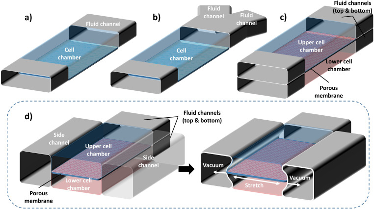
Accurate and stable fluid flow is essential in the OoC devices. The complexity of flow control requirements in OoC devices depends on the complexity of the mimicked function. A general schematic representation of various OoC devices mimicking single organs is shown in Fig. 1. Depending on the chemical and biological analysis, type of organ function, or physiological system, the structural complexity of the OoC devices varies. The simplest OoC device contains one single cell chamber having one cell type and one fluid flow channel [Fig. 1(a)]. These simple OoC devices are, in general, utilized for studying the physiology of the cells related to a particular organ and the influence of different fluids over them.10–13 Single chamber OoC devices can also be designed to have two or more fluid flow channels. In the two-channel configuration, one of the channels is used for cell medium flow while the other one can be used for flowing gases or different doses of drugs to investigate their reaction to organ functions14,15 [Fig. 1(b)]. Double cell chamber OoC devices are developed by stacking one over the other to study tissue interactions and to establish vascular perfusion.16–26 They consist of upper and bottom cell chambers, with a membrane separating them each having independent flow channels [Fig. 1(c)]. Different cell types are grown on both sides of the membrane. In some OoC applications, additional lateral side channels are added to provide sufficient media flow to the main cell chamber.27,28 In many cases, these side channels have no fluidic interaction with the cell chambers and are used to investigate mechanical effects on the membrane by lateral stretching29–31 [Fig. 1(d)].
FIG. 1.
General schematic representations of various basic OoC devices: (a) the simplest OoC device having a single cell chamber and a single fluid channel and (b) an OoC device having a single cell chamber and two fluid channels. One of the fluid channels is to flow cell medium and the other for various drug doses. (c) A double cell chamber and two fluid channels OoC device for mimicking vascularization. This device has upper and lower cell chambers with a micro-fabricated porous elastic membrane at the interface of the chambers. (d) A mechanically stretchable membrane in the OoC device having a double cell chamber and multiple fluid channels. The upper cell chamber can be used to flow air periodically to mimic the lung function. This device is also equipped with two isolated side channels along with the cell chambers. A lateral elongation of the elastic membrane is obtained by applying a vacuum on the side channels, which induces mechanical stretching of the adherent cell layers on the membrane.
Multiple cell chambers were also made for certain single organs such as kidney,32 skin,33 heart,34 and intestine.35 The structural complexity can be further increased to multi-organ functions and interactions by connecting two or more organs36–41 in multiple chambers, such as the gastrointestinal tract,42 four-organs,43 and immune system.44 The most intricate OoC device is a body or human-on-a-chip having multiple organ chambers and multiple channels, with a supply of different fluids at different flow rates.45–48 Table I summarizes some of the literature on various structural complexity levels of OoC applications and relates these to the microfluidic complexity levels. The microfluidic complexity levels are categorized into single, double, and multiple cell/tissue culture chambers. Each of these could have single, double, or multiple fluid flow channels. The OoC applications are categorized into single organ, system-on-a-chip, and complete body/human-on-a-chip.
TABLE I.
General OoC classification depending on the complexity of the microfluidic device (see Fig. 1) and their combinations, represented by the intensity of the color. The columns represent the microfluidic complexity levels concerning the number of cell chambers and microfluidic channels. The rows represent different OoC applications while categorizing them into three main parts: single organ-on-chip, system-on-a-chip, and body/human-on-a-chip.
| Microfluidic complexity OoC application complexity |
Single chamber | Double chamber | Multiple chambers | |||||||
|---|---|---|---|---|---|---|---|---|---|---|
| Single channel | Double channel | Multichannel | Single channel | Double channel | Multichannel | Single channel | Double channel | Multichannel | ||
| Single organ | Tumor | Li et al. (2016)10 | Cho et al. (2016)14 | Ayuso et al. (2016)27 | ||||||
| Miller et al. (2018)15 | ||||||||||
| Liver | Lee et al. (2013)12 | Kane et al. (2006)20 | ||||||||
| Vernetti et al. (2016)11 | ||||||||||
| Skin | Chung et al. (2009)28 | Sriram et al. (2018)17 | Wufuer et al. (2016)33 | |||||||
| BBB | Park et al. (2019)19 | Brown et al. (2015)24 | ||||||||
| Pancreas | Zbinden et al. (2020)13 | Shik Mun et al. (2019)21 | ||||||||
| Kidney | Jang and Suh (2010)16 | Jang et al. (2013)22 | Weinberg et al. (2008)32 | |||||||
| Intestine | Shah et al. (2016)23 | Kasendra et al. (2018)30 | Beaurivage et al. (2020)35 | |||||||
| Kim et al. (2012)29 | ||||||||||
| Heart | Marsano et al. (2016)25 | Chen et al. (2017)34 | ||||||||
| Lung | Benam et al. (2016)18 | Huh et al. (2010)31 | ||||||||
| Stucki et al. (2015)26 | ||||||||||
| System-on-a-chip | Double-organ/co-culture | Park et al. (2012)36 | Kamei et al. (2017)40 | Bovard et al. (2018)38 | ||||||
| Li et al. (2017)39 | Chang et al. (2017)37 | |||||||||
| Multi-organ system | Mahler et al. (2009)42 | Sasserath et al. (2020)44 | ||||||||
| Maschmeyer et al. (2015)43 | ||||||||||
| Maoz et al. (2018)41 | ||||||||||
| Body/human-on-a-chip | Combination of systems | Novak et al. (2020)48 | ||||||||
| Miller et al. (2016)47 | ||||||||||
| Edington et al. (2018)46 | ||||||||||
| Ramme et al. (2018)45 | ||||||||||
B. State-of-the-art commercial OoC devices
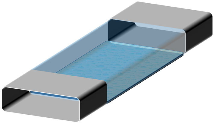
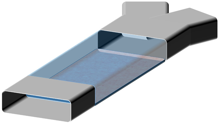
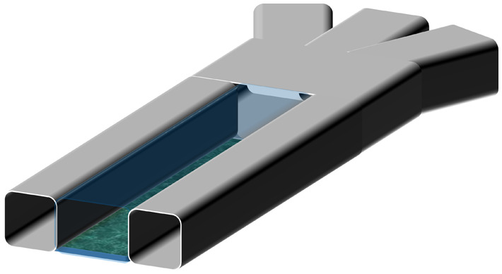
Several commercially available OoC devices were developed by various companies to meet the needs of multi-organ functions. Some of these companies and their OoC device microfluidic complexity levels are shown in Table II. AlveoliX developed AX12 lung-on-chip device to recreate the air–blood barrier of lung alveoli.49 It is based on a 96-well plate format and 12 samples per device could be tested in parallel. The initial sample loading is done via pipetting. This device has an ultrathin membrane mimicking the breathing motion using under-pressure. The device is compatible with readouts, such as transepithelial/endothelial electrical resistance (TEER), enzyme-linked immunosorbent assay (ELISA), reverse transcription polymerase chain reaction (RT-PCR), and flow cytometry. Bi/OND Solutions B.V. developed inCHIPit™, which is a microfluidic device having an open-cell/tissue chamber connected to a microfluidic channel through a porous membrane.50 To connect the device to perfusion systems, a compact and reusable six-well plate branded as comPLATE™ is used. Hesperos Inc. developed Human-on-a-Chip®, which is capable of creating toxicology models with several interlinked organs.51 Emulate Inc. developed the Chip-S1 stretchable chip, which can be configured to emulate different organs.52 The device recreates a dynamic cellular microenvironment of the human body, including tissue-to-tissue interfaces, media flow, and mechanical forces. It has multiple microchannels and a double cell chamber with a stretchable membrane in between. Akura™ Flow developed by InSphero Inc. is used for pre-clinical efficacy and toxicity testing applications in a multi-tissue, microfluidic assay format.53 A gravity-induced flow by using a tilting medium perfusion system is applied in this device. A smart multi-electrode array-chip for pharmacological research was developed by Micronit Microtechnologies B.V. and IMEC.54 The device is based on a 16-well plate format. Hence, multiple tests can be performed in parallel. Mimetas B.V. developed OrganoPlate®, which is a microfluidic 3D cell culture plate having 96 wells.55 Continuous perfusion is done by a gravity-driven leveling system. ParVivo™ disposable microfluidic chip was developed by Nortis.56 The device has different configurations with various degrees of microfluidic complexity. Cells are pre-seeded to the device and it is required to connect an external perfusion device to create controlled fluid flow. PIMCELL is an OoC device developed by PimBio B.V.57 The device has a single chamber and double channel structure and is based on a six-well plate format. These double channels provide “arterial” perfusion and “venous” perfusion to the open access cell chamber. SynVivo Inc. developed different OoC devices having a single/double/multiple chamber and multichannel structures such as idealized co-culture chips (IMN2/IMN3 linear and IMN2/IMN3 radial) and microvascular network chips (SMN1/SMN2/SMN3) for different tissue and organ studies.58 HUMIMIC™ chips are developed by TissUse GmbH.59 These chips are applicable to any kind of cell types or tissues in multiple formats. HUMIMIC Chip2 allows co-cultures. On-chip micropumps to create recirculation are controlled by external pressurized air or vacuum systems to provide pulsatile flow in these devices.
TABLE II.
Commercially available OoC devices, applications, and microfluidic complexities as shown in Fig. 1 and their combinations.
| Company and OoC device name | Applied tissue/organ/system | Microfluidic complexity | Representative image(s) |
|---|---|---|---|
| Micronit Microtechnologies B.V. & IMEC Smart multi-electrode array-chip |
Complex tissue models, heart | Single chamber and single channel |
|
| AlveoliX AX12 |
Lung | Single chamber and double channel |
|
| PimBio B.V. PIMCELL |
Gut, 3D cell culture | ||
| Bi/OND inCHIPit-3C™ |
3D tissues | Single chamber and multichannel |
|
| Emulate Inc. Chip-S1 |
Lung, brain, kidney, liver, intestine | Double chamber and multichannel |
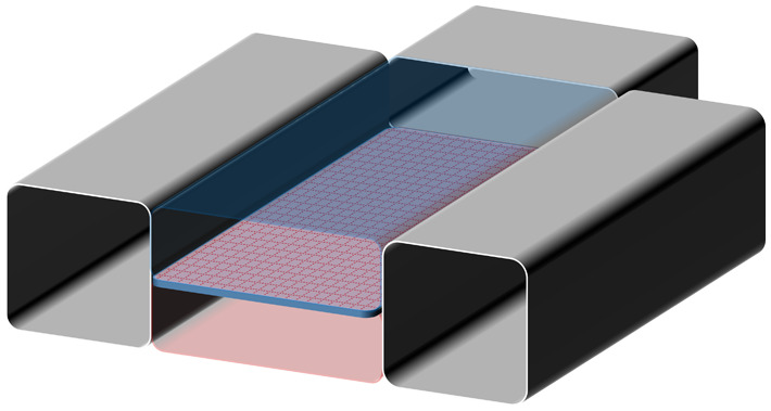
|
| Hesperos Inc. Human-on-a-chip |
2-organ, 3-organ, and 4-organ models | Multiple chambers and single channel |
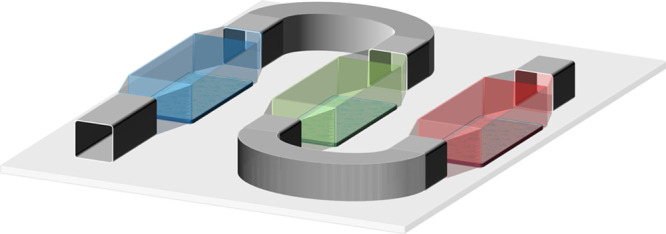
|
| InSphero Inc. Akura™ |
Multi-tissues | Multiple chambers and double channel |
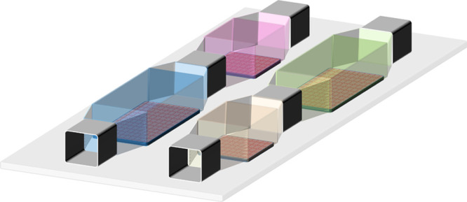
|
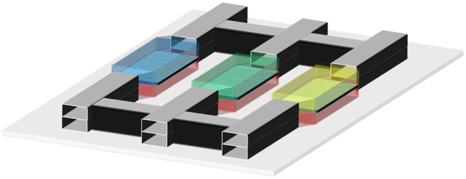
| Mimetas B.V. OrganoPlate® |
3D tissues and organ models3D co-culture of organotypic cells | Multiple chambers and multichannel |
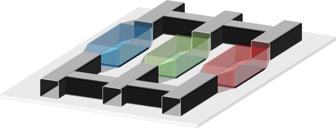
|
| Nortis ParVivo™ |
|||
| SynVivo Inc. IMN 2&3 series (linear and radial) |
Lung, blood-brain barrier, cancer | ||
| TissUse GmbH HUMIMIC™ |
2-organ and 4-organ models |
Some of these OoC device companies also provide perfusion units specific to their own OoC devices. AlveoliX brings AXExchanger and AXBreather to drive the medium and create pneumatic control on the deflection of the microdiaphragm inside the AX12, respectively. These external units are in desktop sizes and connected to the AX12 by external tubings.60 Emulate Inc. provides additional modules such as POD-1 to bring portability and integration to one OoC device (Chip-S1), a desktop-sized culture module (ZOE-CM1) to control fluid flow up to 12 OoC devices.61 Mimetas B.V. developed an external perfusion unit to provide continuous fluid flow in their OoC device. OrganoFlow L is established by passive leveling of liquids as adjustable rocking angles (0° to +25°) and can fit into the incubators.62 Nortis provides portable mini-bioreactors for perfusion of ParVivo chips to be fitted in incubators. To drive the bioreactor, an external pneumatic pump is needed.56 SynVivo provides a pneumatic primer for automated priming of their co-culture OoC devices. This unit is then connected to a pressure source.63
In addition to these efforts, some other peripheral flow control components providers, such as Elveflow,64 Fluigent,65 Convergence Industry B.V.,66 and Dolomite Microfluidics,67 focus on developing peripheral systems to support organ-on-chips in terms of automated, accurate, and stable fluid flow control. They are used in many applications, which are shown in Table I. These systems typically consist of flow/pressure controllers and flow sensors to monitor the flow under dynamic flow conditions. Such peripheral devices provide the ability to perform long-term, reproducible fluid flow for the experiments.
C. Analysis of literature on OoC peripheral control components
The functions needed to realize an OoC are to perform controlled fluid (gases and liquids) flow and to monitor vital parameters (temperature, pH, and fluorescence) with an aim of mimicking cell microenvironment in vivo. These functions are achieved by a combination of passive and active microfluidic components.68–75 Various microfluidic fabrication technologies have enabled the production of flow channels, culture chambers, membranes, and their complex combinations. These devices are usually passive. External energy sources and control systems are needed to activate the functions. Most of the focus so far has been on the development of the OoC devices and their combinations.
Despite OoC devices being small, the external peripheral systems that provide controlled fluid flow are bulky and difficult to integrate. As an example, the size of lung-on-a-chip is about a conventional glass slide (75 × 25 mm2), whereas the peripheral pressure/flow control unit typically occupies a benchtop space.76–78 This is particularly a disadvantage if more complex flow control is required for multiple organs-on-chips, multiple flow rates, multiple channels, multiple chambers, and multiple media. Such applications require a complex peripheral system with multiple components and connections. With the present state-of-the-art technology, this leads to very bulky solutions. Therefore, there is a need for significantly miniaturizing and integrating the peripheral fluid flow control components. That will improve ease of use with different analytical instruments without having to disconnect tubings/cables from OoC, significantly reduces the sample volume usage, reduces unnecessary dead volume in connecting tubes, increases reaching time of chemicals to the OoC cell chamber, and enables to conduct long-term experiments (of the order of several days up to several weeks).43,79,80 Hence, the design of the various fluid flow control components like pumps, valves, fluid selectors (multiplexers), flow sensors, and flow controllers need to be revisited. They should be miniaturized with ease of integration on a suitable platform in a modular format.
Depending on the application, the fluid types that are used in OoC devices vary from liquids (different cell culture media) to gases (air, oxygen, CO2). Vacuum can also be applied when a mechanical stimulus is needed on the cell chambers. Fluid flow rates for different OoC applications vary between a minimum of 1 μl/min and a maximum of 100 μl/min.8,81 Other requirements for the fluid flow can be defined as bubble-free and fluctuation-free flow to protect cells from high shear stresses.5,8,82
II. ARCHITECTURE DESIGN
A. Requirements of the architecture
To improve the ease of overall fluid flow control in an OoC device, the peripheral components that connect with the OoC device should allow modularity, integration, miniaturization, and portability.
1. Modularity and integration
Combining various peripheral control components and microfluidic functions onto one single platform is challenging with state-of-the-art technology.83 Therefore, a flexible modular integration approach is needed for designing OoC platform architecture. It should enable OoC devices and peripheral components to be assembled on a generic substrate as modules. The modular combination of different components on the platform brings configurational flexibility for different applications. Needs for various flow patterns (continuous, pulsatile, and discrete flow8), flow stability (short term and long term), and flow speed indicate that an active fluid displacement source is essential for fluid flow control.
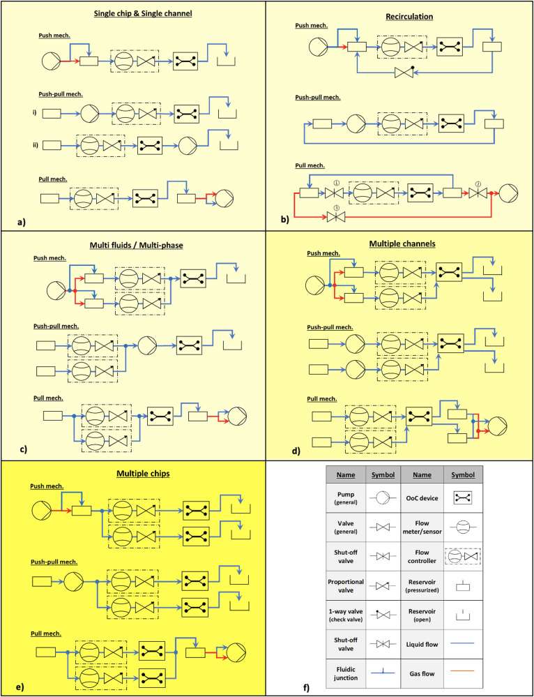
The basic microfluidic flow control peripheral components and their modular connection configurations are shown in Fig. 2.
FIG. 2.
Fluid flow control configurations for different requirements of OoCs. Each requirement can be accomplished by one of the flow control mechanisms: push, push-pull, or pull. The first level of complexity is in light yellow color: (a) single chip and single channel configurations, (b) recirculation configurations, and (c) multiple chip configurations. The second level of complexity is in yellow: (d) multiple channel configurations. The third level of complexity is in dark yellow: (e) multi-fluids/multi-phase configurations. The components: (f) the definition of symbols used in the configurations. These configurations can be used for the applications given in Table I.
They are divided [Figs. 2(a)–2(e)] into different requirements of OoC experiments. The intensity of the yellow color shade represents the level of complexity of the modular connection for those needs. The darker the shade, the higher the complexity. The selection criteria of a configuration in each requirement depend on the choice of the fluid flow control mechanism, i.e., push, push-pull, or pull. In a push mechanism, the fluid in the reservoir is pushed into the microfluidic network either directly with a flow source (blue line represents liquid flow) or indirectly by using a pressure source (red line represents gas flow). In a push-pull mechanism, the fluid displacement is done via reciprocating84–87 or rotary88 principles. In a pull mechanism, an under-pressure (vacuum) is created at the outlet to enable fluid flow through the microfluidic network either directly with a flow source or indirectly with a vacuum source. The strengths and limitations of these mechanisms are given in Table III.
TABLE III.
Comparison of fluid flow control mechanisms as shown in Fig. 2 and relevant reference studies.
| Fluid handling mechanisms | Strengths | Limitations | Reference |
|---|---|---|---|
| Push mechanism | • Syringe pumps/Pressure controllers are widely available. | • Syringe pumps or pressure sources are bulky. | 3,4,6–8,11,13,17,22,29,30 |
| • Fluctuation-free flow with pressure source. | • Fluctuations with syringe pump. | ||
| • For multiple channels to OoC: Single pressure source would suffice. | • Flow controller needed for every flow channel to OoC. | ||
| • Spills liquid if there are leakages. | |||
| • For multiple channels to OoC: Need multiple of them if syringe pump is used. | |||
| Push-pull mechanism | • Pumps have small footprint. Ideal for portability. | • Every flow channel to OoC needs a separate pump | 5,9,10,12,14,16,27,31–35,37,38,40 |
| • Pumps can be exchanged as modules. | • Spills liquid if there are leakages | ||
| • Pump can be used as flow controller if separate pumps are connected to each channel to OoC. | • Pulsating flow. Need extra fluctuation damping mechanism for smooth flow. | ||
| • Recirculation without extra components. | • Preferably different pump for different fluid phase. | ||
| Pull mechanism | • Fluctuation-free fluid flow with vacuum source. | • Vacuum pumps are bulky. Miniature vacuum pumps cannot create enough vacuum or need repeated vacuum generation. Syringe pumps are bulky. | 19,23,24 |
| • Single source for multiple channels, despite multiple channels to OoC. | • Flow controller needed for every flow channel to OoC. | ||
| • Generate bubbles if there are leakages. | |||
| • Recirculation with extra components and process steps. |
For the single chamber and single channel situation [Fig. 2(a)], the components required are a fluid reservoir, pump, flow controller, OoC device, and waste reservoir. Flow controller can be positioned before or after the OoC device or pump. For example, tumor-on-a-chip from Li et al. (2016)10 (Table I), uses a microfluidic perfusion system with a push mechanism.
For recirculation, the connection configuration is shown in Fig. 2(b). All the outlet reservoirs should be connected to the inlet reservoirs in a closed-loop. The push mechanism needs an extra one-way valve in the feedback, whereas a push-pull needs a simple feedback connection of the outlet reservoir to the inlet reservoir. It needs three shut-off valves in the microfluidic circuit. Valves 1 and 2 are open and valve 3 is closed when the fluid is flowing through the OoC. During recirculation, valves 1 and 2 are closed and valve 3 is open. Active recirculation is used for oxygenation of media89 and drug toxicity tests.90 Passive recirculation is used in OrganoPlate® of Mimetas B.V. organ chip models (Table II).
For multi-fluid or multi-phase liquids, shown in Fig. 2(c), the flow rate for each liquid is maintained by flow controllers and a single pump suffices in all three mechanisms. A push mechanism for multiple fluids and multi-phase is used in Huh et al. (2010)31 (Table I).
For single chamber–multiple channels, shown in Fig. 2(d), the configurations become a bit complex. The advantage of using a push or a pull mechanism here is that only one pump would suffice for multiple channels, and the required flow rate is maintained by the flow controllers. However, for the push-pull mechanism, the number of pumps needed is proportional to the number of flow channels. For example, Weinberg et al. (2008)32 uses push mechanism and Sriram et al. (2018)17 uses push-pull mechanism.
For multiple chips, shown in Fig. 2(e), the configurations become the most complex, for example, Novak et al. (2020)48 who use a push mechanism in their setup.
Note that each fluid type, channel, or chip needs a pump and proportional flow controller in all these configurations. Table IV summarizes the required unit function components for each mechanism and different configurations.
TABLE IV.
Fluid flow control mechanisms and required components for increasing complexity of the configurations shown in Fig. 2.
| OoC functional complexity | Fluid handling mechanisms | ||
|---|---|---|---|
| Push mechanism | Push-pull mechanism | Pull mechanism | |
| Single channel to Multi-channel (n) | 1 pump | n pumps | 1 pump |
| n flow controllers | n flow controllers | n flow controllers | |
| Single fluid to multi-fluids (n) | 1 pump | 1 pump | 1 pump |
| n flow controllers | n flow controllers | n flow controllers | |
| Single phase to multi-phase (n) | 1 pump | n pumps | 1 pump |
| n flow controllers | n flow controllers | n flow controllers | |
| Single chip to multi-chip (n) | 1 pump | 1 pump | 1 pump |
| n Flow controllers | n flow controllers | n flow controllers | |
| Single pass to recirculation | Extra component: 1-way valve | No extra components | Extra components: 3 shut-off valves |
| 1 two-step flow | |||
2. Portability and miniaturization
Controlled conditions, such as oxygen and carbon dioxide levels, pH, and temperature, are crucial for the viability of the cells in OoC chambers during experiments. These conditions are currently provided by cell culture incubators. To keep the cell viability conditions, to monitor cell proliferation, to move cells between different analytical instruments, the OoC platform should be portable. For example, the platform should be easy to move in/out of an incubator without disturbing the fluid flow control: (a) to a standard fluorescence microscope, (b) confocal microscope, (c) Raman spectroscope, and (d) chromatography system. It is even desired to develop a cell culture environment on the platform itself enabling long-term experiments. Therefore, there is a need to develop on-chip functions like incubator-on-chip and pH-control-on-chip. These functions are obtained by additional components such as heaters, temperature sensors, oxygenators, pH sensors, and corresponding electronics integrated on the platform in modules.
In order to achieve portability in OoC platforms, miniaturization of the peripheral components that control the fluid flow has an important role. Having more than one unit function in a platform requires multiplied component numbers depending on the requirements of the experiment leading to an increase in the footprint of the total platform. Therefore, there is a need to miniaturize external flow control peripheral systems in order to bring OoC devices and control components onto a single portable platform. Furthermore, having a modular architecture to connect various peripheral components on the platform enables the easy exchange of different peripheral systems. The other challenge is to bring electrical and fluidic components and their respective connections together on a single platform.
Along with miniaturization and portability, accurate and stable flow control is also required. For example, to investigate fluid shear stress effects on cells91,92 with a very low perfusion speed (typically 0.83–1.67 μl/min).93 A wide range of shear stress amplitudes is applied on different types of cells from lowest values as 1.5 × 10⁻⁴–4.1 × 10⁻⁴ Pa to highest values up to 13 Pa.91 A luminal fluid shear stress of 0.02–2 Pa was reported to mimic urinary flow in a kidney-on-a-chip device16 and a fluid-induced shear stress of 1.5 Pa was obtained in a human-breathing lung-on-a-chip device to precondition the endothelial cells.31 The typical duration for shear stress experiments is between a few hours to 30 days in some cases.94 To provide accuracy and stability in fluid flow, integrated sensors and actuators are needed.95
B. Proposed architecture
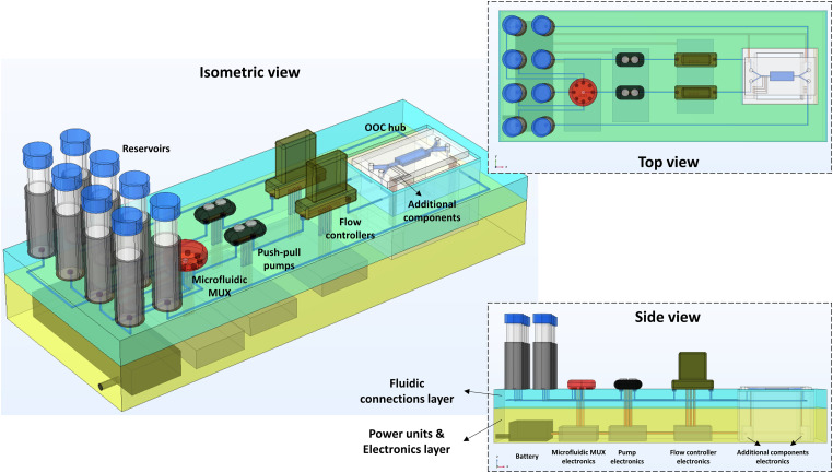
We propose a three-layered modular, integrated, and portable microfluidics platform for the next generation OoC experiments (Fig. 3). The top layer is for components, the middle layer is for the microfluidic network, and the bottom layer is for electronics. In the top component layer, the physical components like the OoC, reservoirs, pumps, flow controllers, and sensors are mounted in modules. In the middle microfluidics layer, the microfluidic network of channels carrying the fluid flow is located. The channel paths are application-specific, that is, optimized for minimum dead volume and desired fluidic resistance. The channels can be manufactured by 3D printing, injection molding, replication methods, etc. The other option for this layer is to create a microfluidic breadboard with many channels running parallel with options to tap from the top. The channels should have appropriate fluidic ports at the top components layer for connections.
FIG. 3.
A microfluidic platform architecture of push-pull mechanism designed for double channel and double chamber OoC device [Fig. 1(c)]. This example configuration is suitable for kidney-on-chip [Jang et al. (2013)22 shown in Table I] and uses a modular configuration of push-pull mechanism as shown in Fig. 2(d) with the addition of microfluidic multiplexer to the second channel to switch between the different fluids in the reservoirs. Microfluidic components are connected via interconnections to the fluidic (blue) and electronics (yellow) layers. Upright and inverse microscopic imaging is possible via the OoC hub window. The fluidic components can be exchanged when needed on the top layer (out of plane) to permit modifications of desired configurations.
The bottom electronics layer consists of a rechargeable battery, power/control electronic printed circuit boards (PCBs), computer interface (if necessary), and Bluetooth for wireless data transfer. The electrical connections to the components on the top layer go through the microfluidics layer. The region where the OoC is mounted should be made open and accessible to the microscope for visualization.
The opening should be designed to mount the OoC at various depths suitable for both upright microscopes and inverted microscopes. The proposed architecture can be implemented for all the configurations described in Fig. 2.
C. Initial results
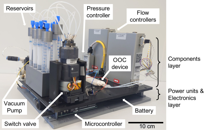
In the pursuit toward achieving a modular, integrated, miniaturized, and portable microfluidics platform using the proposed architecture, we made an initial attempt at the implementation with available commercial components. We have developed a proof-of-concept integrated platform suitable for lung-on-a-chip, gut-on-a-chip, and tissue-on-chip using off-the-shelf fluid flow control components (Fig. 4).96 The configuration shown for the pull mechanism in Fig. 2(d) was implemented. The commercial fluidic components (OoC, flow sensor, flow controllers, pump, valves, and switch valve) were placed on the top layer. The control electronics and a rechargeable battery were placed underneath. To avoid any influence of heat, the heat dissipating electrical components and battery were placed far away from the OoC. A thermally insulating 3D-printed polylactic acid (PLA) material was used for the platform to prevent further dissipation of heat to the OoC.
FIG. 4.
A preliminary version of the OoC platform, which is implemented by using off-the-shelf peripheral components. It is suitable for OoC functions of the lung, gut, and tissue. It is modular, uses the pull mechanism [Fig. 2(d)], and can sequentially control seven liquids, air, and vacuum in multiple channels. All fluidic control components are integrated on a single platform. The components are placed on the top layer while electronics and power units are placed on a 3D-printed plate at the base. The organ chip is placed on the platform with access from top or bottom suitable to fit on the x–y table of an upright or inverted microscope.
The entire platform is portable and works on a battery. The components were positioned on the platform such that the entire platform could be placed on an optical microscope table to monitor the channels and chambers in the OoC device without having to disconnect any tubes or cables. The system is reasonably modular with the capability to exchange selected components. Even for this simple implementation of an integrated microfluidic OoC platform, the overall system is still bulky.
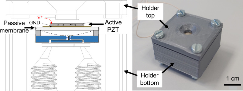
In the effort toward miniaturized components, we made a miniaturized proportional control valve manufactured by 3D printing (Fig. 5).97 The valve is based on a piezoelectric unimorph. The flow rate through the valve is proportionally controlled by the amount of voltage applied to the piezoelectric element placed on top of a membrane. The valve is modular and can be connected to a microfluidic circuit. Looking at the basic necessary peripheral components (Fig. 2), there is a need for miniaturization of the other key components: fluctuation-free pumps87,98,99 and flow controllers. For multiple fluids, a miniaturized fluid multiplexer is needed (Fig. 3).
FIG. 5.
(a) Schematic of the proportional microvalve having piezoelectric unimorph microactuator and the CAD drawing of valve holder, (b) Assembled valve holder having microvalve placed in it, suitable to place in the architecture shown in Fig. 2.
One of the challenges in OoC devices is the formation of gas bubbles in fluid flow.100 They are typically minimized/eliminated by degassing the fluids or using limited amount of pressure applied that does not dissolve gas inside liquids.101 Our proposed architecture also allows us to connect “bubble traps” in the microfluidic circuit. Leak-free tight fluidic connectors are always beneficial for well-functioning of the OoC device.
Sterilization of the flow control components and the OoC chip is another important aspect.102 To keep the system sterile, materials that can withstand temperature, radiation, and chemicals associated with sterilization will be used. With modularity, individual components can be separately sterilized or replaced, if necessary.
There is also a need to develop standards for connectors (fluidic and electrical) to enable easy interoperability among peripheral fluid flow control devices and OoC devices from different sources.103 Then establishing software with a library of fluid control functions and components will enable design of peripheral components for a desired OoC requirement and simulate the fluid flow path. An interface to advanced numerical finite element simulation programs will enable a better understanding of the flow behavior when different functions are combined. Once a complete connection (fluidic and electrical) configuration is reached for a particular experiment, a modular, portable platform is produced.
III. CONCLUSION
Microfluidic OoCs typically need functions like accurate and stable multiple fluid flow control (different liquids having varying flow rates between 1 and 100 μl/min, air for oxygenation of cells, and vacuum for stretching membranes of cell-substrate), 37 °C temperature control for cell viability, pH sensing to monitor cell oxygenation levels, and material transparency to view fluorescence signals. All these functions need many peripheral control components that will become very complicated and bulky with an increase in the number of organs to be implemented. The research effort so far has been on the fabrication of the organ chips themselves, but very little on the integration and miniaturization of the peripheral control components. We propose a three-layer architecture that supports a modular, integrated, and portable platform for OoC chips, peripheral control, and sensing components. Modular fluid flow control configurations for different requirements of OoCs are given. Each requirement can be accomplished by one of the flow control mechanisms: push, push-pull, or pull. We showed a preliminary version of the proposed architecture using off-the-shelf components suitable to investigate lung, gut, and tissue functions. Our next developments will be in (a) fabrication of integrated boards that contain fluid channels and electric connections layout and (b) miniaturization of flow control components (like proportional valves, pumps, fluid multiplexers, and flow controllers). These developments will lead to obtaining a modular, integrated, miniaturized, and portable OoC platform. The proposed architecture can also be used in other applications of microfluidics, such as bioreactors for biopharmaceuticals, food safety, and environmental monitoring.
ACKNOWLEDGMENTS
We thank Mr. Haoyu Zhu for his contribution to implementing the proof-of-concept integrated platform and Mr. Arun Gunda for his contribution to implementing a proportional microvalve. This work was supported by Top consortium voor Kennis en Innovatie (TKI) High Tech Systemen en Materialen (HTSM) and Nano Engineering Research Initiative (NERI) of the Delft University of Technology in collaboration with Bronkhorst High-Tech B.V under the project titled iMicrofluidics.
AUTHOR DECLARATIONS
Conflict of Interest
All authors declare no conflicts of interest.
Author Contributions
G.Ö., M.K.G., J.L., and M.T. came up with the idea of three-layered architecture. G.Ö. conceptualized the fluid flow control connection configurations. G.Ö. and M.K.G. prepared the initial draft. M.K.G, J.L., and M.T. supervised the work and are responsible for overseeing the entire effort. All the authors gave their comments on the manuscript and improved the writing.
DATA AVAILABILITY
The data that support the findings of this study are available from the corresponding author upon reasonable request.
NOMENCLATURE
| Cell chamber | Engineered environment of microfluidic compartments in OoC devices where cells are seeded, grown, and tested. |
| Flow connection configuration | A particular combination of fluid control components to steer the flow inside an OoC based on certain requirements of the OoC experiment. |
| Flow mechanism | Steering of the fluid either by pushing, push-pull, or pulling. |
| Fluid channel | Embedded channels that connect the cell chambers to inlet and outlets of OoC devices to provide required fluid flow. |
| OoC device | A microfluidic chip enabling mimicking the human organ functions by having cell/organ chambers and microchannels. |
| OoC platform | Combination of fluidics and electrical components connected in a certain architecture that allows performing a set of fluidic functions in an OoC device. These functions are enabled by a set of fluid flow control components. |
REFERENCES
- 1.Bhatia S. N. and Ingber D. E., Nat. Biotechnol. 32, 760 (2014). 10.1038/nbt.2989 [DOI] [PubMed] [Google Scholar]
- 2.Ingber D. E., Development 145, dev156125 (2018). 10.1242/dev.156125 [DOI] [PMC free article] [PubMed] [Google Scholar]
- 3.See https://www.fda.gov/files/food/published/Organs-On-Chips-Technology-Infographic.pdf (2021) for more information about the technology and three main components of the system (last accessed 01 April 2022).
- 4.Wu Q., Liu J., Wang X., Feng L., Wu J., Zhu X., Wen W., and Gong X., Biomed. Eng. Online 19, 9 (2020). 10.1186/s12938-020-0752-0 [DOI] [PMC free article] [PubMed] [Google Scholar]
- 5.Low L. A., Mummery C., Berridge B. R., Austin C. P., and Tagle D. A., Nat. Rev. Drug Discov. 20, 345 (2021). 10.1038/s41573-020-0079-3 [DOI] [PubMed] [Google Scholar]
- 6.Azizipour N., Avazpour R., Rosenzweig D. H., and Sawan M., Micromachines 11, 1 (2020). [DOI] [PMC free article] [PubMed] [Google Scholar]
- 7.Zhang B., Korolj A., Fook Lun Lai B., and Radisic M., Nat. Rev. Mater. 3, 257 (2018). [Google Scholar]
- 8.Kaarj K. and Yoon J. Y., Micromachines 10, 700 (2019). 10.3390/mi10100700 [DOI] [PMC free article] [PubMed] [Google Scholar]
- 9.Rogal J., Probst C., and Loskill P., Future Sci. OA 3, 1 (2017). [DOI] [PMC free article] [PubMed] [Google Scholar]
- 10.Li Y., Gao A. X., and Yu L., Appl. Biochem. Biotechnol. 178, 114 (2016). 10.1007/s12010-015-1862-1 [DOI] [PubMed] [Google Scholar]
- 11.Vernetti L. A., Senutovitch N., Boltz R., DeBiasio R., Ying Shun T., Gough A., and Taylor D. L., Exp. Biol. Med. 241, 101 (2016). 10.1177/1535370215592121 [DOI] [PMC free article] [PubMed] [Google Scholar]
- 12.Lee S. H. S. A., No D. Y., Kang E., Ju J., Kim D. S., and Lee S. H. S. A., Lab Chip 13, 3529 (2013). 10.1039/c3lc50197c [DOI] [PubMed] [Google Scholar]
- 13.Zbinden A., Marzi J., Schlünder K., Probst C., Urbanczyk M., Black S., Brauchle E. M., Layland S. L., Kraushaar U., Duffy G., Schenke-Layland K., and Loskill P., Matrix Biol. 85–86, 205 (2020). 10.1016/j.matbio.2019.06.008 [DOI] [PubMed] [Google Scholar]
- 14.Cho S., Islas-Robles A., Nicolini A. M., Monks T. J., and Yoon J. Y., Biosens. Bioelectron. 86, 697 (2016). 10.1016/j.bios.2016.07.015 [DOI] [PMC free article] [PubMed] [Google Scholar]
- 15.Miller C. P., Tsuchida C., Zheng Y., Himmelfarb J., and Akilesh S., Neoplasia 20, 610 (2018). [DOI] [PMC free article] [PubMed] [Google Scholar]
- 16.Jang K. J. and Suh K. Y., Lab Chip 10, 36 (2010). 10.1039/B907515A [DOI] [PubMed] [Google Scholar]
- 17.Sriram G., Alberti M., Dancik Y., Wu B., Wu R., Feng Z., Ramasamy S., Bigliardi P. L., Bigliardi-Qi M., and Wang Z., Mater. Today 21, 326 (2018). 10.1016/j.mattod.2017.11.002 [DOI] [Google Scholar]
- 18.Benam K. H., Villenave R., Lucchesi C., Varone A., Hubeau C., Lee H. H., Alves S. E., Salmon M., Ferrante T. C., Weaver J. C., Bahinski A., Hamilton G. A., and Ingber D. E., Nat. Methods 13, 151 (2016). [DOI] [PubMed] [Google Scholar]
- 19.Park T. E., Mustafaoglu N., Herland A., Hasselkus R., Mannix R., FitzGerald E. A., Prantil-Baun R., Watters A., Henry O., Benz M., Sanchez H., McCrea H. J., Goumnerova L. C., Song H. W., Palecek S. P., Shusta E., and Ingber D. E., Nat. Commun. 10, 2621 (2019). 10.1038/s41467-019-10588-0 [DOI] [PMC free article] [PubMed] [Google Scholar]
- 20.Kane B. J., Zinner M. J., Yarmush M. L., and Toner M., Anal. Chem. 78, 4291 (2006). 10.1021/ac051856v [DOI] [PubMed] [Google Scholar]
- 21.Shik Mun K., Arora K., Huang Y., Yang F., Yarlagadda S., Ramananda Y., Abu-El-Haija M., Palermo J. J., Appakalai B. N., Nathan J. D., and Naren A. P., Nat. Commun. 10, 1 (2019). 10.1038/s41467-019-11178-w [DOI] [PMC free article] [PubMed] [Google Scholar]
- 22.Jang K. J., Mehr A. P., Hamilton G. A., McPartlin L. A., Chung S., Suh K. Y., and Ingber D. E., Integr. Biol. 5, 1119 (2013). 10.1039/c3ib40049b [DOI] [PubMed] [Google Scholar]
- 23.Shah P., Fritz J. V., Glaab E., Desai M. S., Greenhalgh K., Frachet A., Niegowska M., Estes M., Jäger C., Seguin-Devaux C., Zenhausern F., and Wilmes P., Nat. Commun. 7, 1 (2016). 10.1038/ncomms11535 [DOI] [PMC free article] [PubMed] [Google Scholar]
- 24.Brown J. A., Pensabene V., Markov D. A., Allwardt V., Diana Neely M., Shi M., Britt C. M., Hoilett O. S., Yang Q., Brewer B. M., Samson P. C., McCawley L. J., May J. M., Webb D. J., Li D., Bowman A. B., Reiserer R. S., and Wikswo J. P., Biomicrofluidics 9, 054124 (2015). 10.1063/1.4934713 [DOI] [PMC free article] [PubMed] [Google Scholar]
- 25.Marsano A., Conficconi C., Lemme M., Occhetta P., Gaudiello E., Votta E., Cerino G., Redaelli A., and Rasponi M., Lab Chip 16, 599 (2016). 10.1039/C5LC01356A [DOI] [PubMed] [Google Scholar]
- 26.Stucki A. O., Stucki J. D., Hall S. R. R., Felder M., Mermoud Y., Schmid R. A., Geiser T., and Guenat O. T., Lab Chip 15, 1302 (2015). 10.1039/C4LC01252F [DOI] [PubMed] [Google Scholar]
- 27.Ayuso J. M., Virumbrales-Muñoz M., Lacueva A., Lanuza P. M., Checa-Chavarria E., Botella P., Fernández E., Doblare M., Allison S. J., Phillips R. M., Pardo J., Fernandez L. J., and Ochoa I., Sci. Rep. 6, 1 (2016). 10.1038/srep36086 [DOI] [PMC free article] [PubMed] [Google Scholar]
- 28.Chung S., Sudo R., MacK P. J., Wan C. R., Vickerman V., and Kamm R. D., Lab Chip 9, 269 (2009). 10.1039/B807585A [DOI] [PubMed] [Google Scholar]
- 29.Kim H. J., Huh D., Hamilton G., and Ingber D. E., Lab Chip 12, 2165 (2012). 10.1039/c2lc40074j [DOI] [PubMed] [Google Scholar]
- 30.Kasendra M., Tovaglieri A., Sontheimer-Phelps A., Jalili-Firoozinezhad S., Bein A., Chalkiadaki A., Scholl W., Zhang C., Rickner H., Richmond C. A., Li H., Breault D. T., and Ingber D. E., Sci. Rep. 8, 1 (2018). 10.1038/s41598-018-21201-7 [DOI] [PMC free article] [PubMed] [Google Scholar]
- 31.Huh D., Matthews B. D., Mammoto A., Montoya-Zavala M., Yuan Hsin H., and Ingber D. E., Science 328, 1662 (2010). 10.1126/science.1188302 [DOI] [PMC free article] [PubMed] [Google Scholar]
- 32.Weinberg E., Kaazempur-Mofrad M., and Borenstein J., Int. J. Artif. Organs 31, 508 (2008). [DOI] [PubMed] [Google Scholar]
- 33.Wufuer M., Lee G. H., Hur W., Jeon B., Kim B. J., Choi T. H., and Lee S. H., Sci. Rep. 6, 1 (2016). 10.1038/srep37471 [DOI] [PMC free article] [PubMed] [Google Scholar]
- 34.Chen Y. Y., Chan H. N., Michael S. A., Shen Y., Chen Y. Y., Tian Q., Huang L., and Wu H., Lab Chip 17, 653 (2017). 10.1039/C6LC01427E [DOI] [PubMed] [Google Scholar]
- 35.Beaurivage C., Kanapeckaite A., Loomans C., Erdmann K. S., Stallen J., and Janssen R. A. J., Sci. Rep. 10, 1 (2020). 10.1038/s41598-020-78359-2 [DOI] [PMC free article] [PubMed] [Google Scholar]
- 36.Park S. H., Sim W. Y., Min B. H., Yang S. S., Khademhosseini A., and Kaplan D. L., PLoS One 7, e46689 (2012). 10.1371/journal.pone.0046689 [DOI] [PMC free article] [PubMed] [Google Scholar]
- 37.Chang S. Y., Weber E. J., Sidorenko V. S., Chapron A., Yeung C. K., Gao C., Mao Q., Shen D., Wang J., Rosenquist T. A., Dickman K. G., Neumann T., Grollman A. P., Kelly E. J., Himmelfarb J., and Eaton D. L., JCI Insight 2, 1 (2017). 10.1172/jci.insight.95978 [DOI] [PMC free article] [PubMed] [Google Scholar]
- 38.Bovard D., Sandoz A., Luettich K., Frentzel S., Iskandar A., Marescotti D., Trivedi K., Guedj E., Dutertre Q., Peitsch M. C., and Hoeng J., Lab Chip 18, 3814 (2018). 10.1039/C8LC01029C [DOI] [PubMed] [Google Scholar]
- 39.Li Z., Su W., Zhu Y., Tao T., Li D., Peng X., and Qin J., Biomicrofluidics 11, 034114 (2017). 10.1063/1.4984768 [DOI] [PMC free article] [PubMed] [Google Scholar]
- 40.Kamei K. I., Kato Y., Hirai Y., Ito S., Satoh J., Oka A., Tsuchiya T., Chen Y., and Tabata O., RSC Adv. 7, 36777 (2017). 10.1039/C7RA07716E [DOI] [Google Scholar]
- 41.Maoz B. M., Herland A., Fitzgerald E. A., Grevesse T., Vidoudez C., Pacheco A. R., Sheehy S. P., Park T. E., Dauth S., Mannix R., Budnik N., Shores K., Cho A., Nawroth J. C., Segrè D., Budnik B., Ingber D. E., and Parker K. K., Nat. Biotechnol. 36, 865 (2018). [DOI] [PMC free article] [PubMed] [Google Scholar]
- 42.Mahler G. J., Esch M. B., Glahn R. P., and Shuler M. L., Biotechnol. Bioeng. 104, 193 (2009). 10.1002/bit.22366 [DOI] [PubMed] [Google Scholar]
- 43.Maschmeyer I., Lorenz A. K., Schimek K., Hasenberg T., Ramme A. P., Hübner J., Lindner M., Drewell C., Bauer S., Thomas A., Sambo N. S., Sonntag F., Lauster R., and Marx U., Lab Chip 15, 2688 (2015). 10.1039/C5LC00392J [DOI] [PubMed] [Google Scholar]
- 44.Sasserath T., Rumsey J. W., McAleer C. W., Bridges L. R., Long C. J., Elbrecht D., Schuler F., Roth A., Bertinetti-LaPatki C., Shuler M. L., and Hickman J. J., Adv. Sci. 7, 2000323 (2020). 10.1002/advs.202000323 [DOI] [PMC free article] [PubMed] [Google Scholar]
- 45.Ramme A. P., Koenig L., Hasenberg T., Schwenk C., Magauer C., Faust D., Lorenz A., Krebs A., Drewell C., Schirrmann K., Vladetic A., Lin G.-C., Pabinger S., Neuhaus W., Bois F., Lauster R., Marx U., and Dehne E.-M., BioRxiv 376970 (2018). 10.1101/376970 [DOI]
- 46.Edington C. D., Chen W. L. K., Geishecker E., Kassis T., Soenksen L. R., Bhushan B. M., Freake D., Kirschner J., Maass C., Tsamandouras N., Valdez J., Cook C. D., Parent T., Snyder S., Yu J., Suter E., Shockley M., Velazquez J., Velazquez J. J., Stockdale L., Papps J. P., Lee I., Vann N., Gamboa M., Labarge M. E., Zhong Z., Wang X., Boyer L. A., Lauffenburger D. A., Carrier R. L., Communal C., Tannenbaum S. R., Stokes C. L., Hughes D. J., Rohatgi G., Trumper D. L., Cirit M., and Griffith L. G., Sci. Rep. 8, 1 (2018). 10.1038/s41598-018-22749-0 [DOI] [PMC free article] [PubMed] [Google Scholar]
- 47.Miller P. G. and Shuler M. L., Biotechnol. Bioeng. 113, 2213 (2016). 10.1002/bit.25989 [DOI] [PubMed] [Google Scholar]
- 48.Novak R., Ingram M., Marquez S., Das D., Delahanty A., Herland A., Maoz B. M., Jeanty S. S. F., Somayaji M. R., Burt M., Calamari E., Chalkiadaki A., Cho A., Choe Y., Chou D. B., Cronce M., Dauth S., Divic T., Fernandez-Alcon J., Ferrante T., Ferrier J., FitzGerald E. A., Fleming R., Jalili-Firoozinezhad S., Grevesse T., Goss J. A., Hamkins-Indik T., Henry O., Hinojosa C., Huffstater T., Jang K. J., Kujala V., Leng L., Mannix R., Milton Y., Nawroth J., Nestor B. A., Ng C. F., O’Connor B., Park T. E., Sanchez H., Sliz J., Sontheimer-Phelps A., Swenor B., Thompson G., Touloumes G. J., Tranchemontagne Z., Wen N., Yadid M., Bahinski A., Hamilton G. A., Levner D., Levy O., Przekwas A., Prantil-Baun R., Parker K. K., and Ingber D. E., Nat. Biomed. Eng. 4, 407 (2020). 10.1038/s41551-019-0497-x [DOI] [PMC free article] [PubMed] [Google Scholar]
- 49.See https://www.alveolix.com/our-technology/#organs-on-chip for more information about Organs-on-Chip (last accessed February 1, 2021).
- 50.See https://www.gobiond.com/products/ for more information about inCHIPit™ and comPLATE™ (last accessed February 1, 2021).
- 51.See https://hesperosinc.com/technology/ for more information about Hesperos Human-on-a-Chip (last accessed February 9, 2021).
- 52.See https://www.emulatebio.com/products for more information about CHIP-S1™ STRETCHABLE CHIP (last accessed February 1, 2021).
- 53.See https://insphero.com/science/enabling-technology/microphysiological-systems/ for more information about Akura™ Flow—InSphero (last accessed February 9, 2021).
- 54.See https://www.micronit.com/get-inspired/showcases/Smart-organ-on-a-chip-platform-for-drug-testing for more information about organ-on-a-chip (last accessed 01 April 2022).
- 55.See https://mimetas.com/page/products for more information about OrganoPlate (last accessed February 1, 2021).
- 56.See https://nortisbio.com/products for more information about ParVivo by Nortis (last accessed February 9, 2021).
- 57.See https://www.pimbio.com/ for more information about PimBio (last accessed February 1, 2021).
- 58.See https://www.synvivobio.com/products/ for more information about SynVivo (last accessed February 1, 2021).
- 59.See https://www.tissuse.com/en/humimic/chips/ for more information about HUMIMIC chips (last accessed February 1, 2021).
- 60.See https://www.alveolix.com/our-products/#ax-lung-on-chip-system for more information about AX lung-on-chip system (last accessed March 15, 2021).
- 61.See https://www.emulatebio.com/our-technology for more information about human emulation system (last accessed March 15, 2021).
- 62.See https://mimetas.com/page/organoflow-l for more information about OrganoFlow L rocker platform (last accessed March 15, 2021).
- 63.See https://www.synvivobio.com/instruments/#1588022149585-78fb0a0f-2673 for more information about Pneumatic primer for automated priming of the co-culture SynVivo chips (last accessed March 15, 2021).
- 64.See https://www.elveflow.com/microfluidic-products/microfluidics-application-packs/organ-on-a-chip-pack/ for more information about Elveflow OOC Pack (last accessed February 9, 2021).
- 65.See https://www.fluigent.com/resources-support/expertise/application-notes/pressure-as-a-tool-to-evaluate-cell-growth/ for use of Fluigent pressure controllers (last accessed 01 April 2022).
- 66.See https://www.con-vergence.com/making-the-difference-in-organ-on-chip-research/ for more information about Convergence Industry B.V. (last accessed February 9, 2021).
- 67.See https://www.dolomite-microfluidics.com/product-category/microfluidic-components/ for more information about dolomite microfluidics—microfluidic components (last accessed May 26, 2021).
- 68.Mark D., Haeberle S., Roth G., Von Stetten F., Zengerle R., von Stetten F., and Zengerle R., Chem. Soc. Rev. 39, 1153 (2010). 10.1039/b820557b [DOI] [PubMed] [Google Scholar]
- 69.Dekker S., Buesink W., Blom M., Alessio M., Verplanck N., Hihoud M., Dehan C., César W., Le Nel A., van den Berg A., and Odijk M., Sens. Actuators B: Chem. 272, 468 (2018). 10.1016/j.snb.2018.04.005 [DOI] [Google Scholar]
- 70.Owens C. E. and Hart A. J., Lab Chip 18, 890 (2018). 10.1039/C7LC00951H [DOI] [PubMed] [Google Scholar]
- 71.Chen X., Mo D., and Gong M., Micromachines 11, 224 (2020). 10.3390/mi11020224 [DOI] [PMC free article] [PubMed] [Google Scholar]
- 72.Lee Y., Kim B., Oh I., and Choi S., Small 14, 1802769 (2018). 10.1002/smll.201802769 [DOI] [PubMed] [Google Scholar]
- 73.Bhargava K. C., Thompson B., and Malmstadt N., Proc. Natl. Acad. Sci. U.S.A. 111, 15013 (2014). 10.1073/pnas.1414764111 [DOI] [PMC free article] [PubMed] [Google Scholar]
- 74.Ong L. J. Y., Ching T., Chong L. H., Arora S., Li H., Hashimoto M., Dasgupta R., Yuen P. K., and Toh Y. C., Lab Chip 19, 2178 (2019). 10.1039/C9LC00160C [DOI] [PubMed] [Google Scholar]
- 75.Chen Y.-S. S., Ma Y.-D. D., Chen C., Shiesh S.-C. C., and Bin Lee G.-B., Lab Chip 19, 3305 (2019). 10.1039/C9LC00624A [DOI] [PubMed] [Google Scholar]
- 76.See https://www.elveflow.com/microfluidic-products/microfluidics-flow-control-systems/ob1-pressure-controller/ for more information about Elveflow microfluidic pressure controller (last accessed May 5, 2021).
- 77.See https://www.fluigent.com/research/instruments/pressure-flow-controllers/mfcs-series/ for Fluigent – MFCSTM-EZ Microfluidic flow control system (last accessed 01 April 2022).
- 78.See https://www.kdscientific.com/products/infusion-syringe-pumps.html for more information about kdScientific—infusion syringe pumps (last accessed June 15, 2021).
- 79.Materne E. M., Maschmeyer I., Lorenz A. K., Horland R., Schimek K. M. S., Busek M., Sonntag F., Lauster R., and Marx U., J. Vis. Exp. 2015, e52526 (2015). 10.3791/52526 [DOI] [PMC free article] [PubMed] [Google Scholar]
- 80.Konar D., Devarasetty M., Yildiz D. V., Atala A., and Murphy S. V., Biomed. Eng. Comput. Biol. 7s1, BECB.S34252 (2016). 10.4137/BECB.S34252 [DOI] [PMC free article] [PubMed] [Google Scholar]
- 81.Yin L., Du G., Zhang B., Zhang H., Yin R., Zhang W., and Yang S. M., Sci. Rep. 10, 1 (2020). 10.1038/s41598-019-56847-4 [DOI] [PMC free article] [PubMed] [Google Scholar]
- 82.Sosa-Hernández J. E., Villalba-Rodríguez A. M., Romero-Castillo K. D., Aguilar-Aguila-Isaías M. A., García-Reyes I. E., Hernández-Antonio A., Ahmed I., Sharma A., Parra-Saldívar R., and Iqbal H. M. N., Micromachines 9, 536 (2018). 10.3390/mi9100536 [DOI] [PMC free article] [PubMed] [Google Scholar]
- 83.Sin M. L. Y., Gao J., Liao J. C., and Wong P. K., J. Biol. Eng. 5, 6 (2011). 10.1186/1754-1611-5-6 [DOI] [PMC free article] [PubMed] [Google Scholar]
- 84.Cazorla P. H., Fuchs O., Cochet M., Maubert S., Le Rhun G., Fouillet Y., and Defay E., Sens. Actuators A 250, 35 (2016). 10.1016/j.sna.2016.09.012 [DOI] [Google Scholar]
- 85.Shoji E., Sens. Actuators B 237, 660 (2016). 10.1016/j.snb.2016.06.153 [DOI] [Google Scholar]
- 86.Gidde R. R., Pawar P. M., Ronge B. P., and Dhamgaye V. P., Microsyst. Technol. 25, 509 (2019). 10.1007/s00542-018-3987-y [DOI] [Google Scholar]
- 87.See https://www.bartels-mikrotechnik.de/en/micropumps/ for more information about Bartels Mikrotechnik—mp6 micropumps (last accessed May 5, 2021).
- 88.Matteucci M., Pérennès F., Marmiroli B., Miotti P., Vaccari L., Gosparini A., Turchet A., and Di Fabrizio E., Microelectron. Eng. 83, 1288 (2006). 10.1016/j.mee.2006.01.259 [DOI] [Google Scholar]
- 89.Oomen P. E., Skolimowski M. D., and Verpoorte E., Lab Chip 16, 3394 (2016). 10.1039/C6LC00772D [DOI] [PubMed] [Google Scholar]
- 90.Zhang C., Zhao Z., Abdul Rahim N. A., Van Noort D., and Yu H., Lab Chip 9, 3185 (2009). 10.1039/b915147h [DOI] [PubMed] [Google Scholar]
- 91.Shemesh J., Jalilian I., Shi A., Heng Yeoh G., Knothe Tate M. L., and Ebrahimi Warkiani M., Lab Chip 15, 4114 (2015). 10.1039/C5LC00633C [DOI] [PubMed] [Google Scholar]
- 92.Varma S. and Voldman J., Lab Chip 18, 3333 (2018). 10.1039/C8LC00746B [DOI] [PMC free article] [PubMed] [Google Scholar]
- 93.Allwardt V., Ainscough A. J., Viswanathan P., Sherrod S. D., McLean J. A., Haddrick M., and Pensabene V., Bioengineering 7, 112 (2020). 10.3390/bioengineering7030112 [DOI] [PMC free article] [PubMed] [Google Scholar]
- 94.Liu L., Loutherback K., Liao D., Yeater D., Lambert G., Estévez-Torres A., Sturm J. C., Getzenberg R. H., and Austin R. H., Lab Chip 10, 1807 (2010). 10.1039/c003509b [DOI] [PMC free article] [PubMed] [Google Scholar]
- 95.Junaid A., Mashaghi A., Hankemeier T., and Vulto P., Curr. Opin. Biomed. Eng. 1, 15 (2017). 10.1016/j.cobme.2017.02.002 [DOI] [Google Scholar]
- 96.Zhou H., “Portable and integrated organ-on-chip platform using off-the-shelf components,” MSc thesis—PME/3ME/TU Delft (2020). [Google Scholar]
- 97.Gunda A., Özkayar G., Tichem M., and Ghatkesar M. K., Micromachines 11, 130 (2020). 10.3390/mi11020130 [DOI] [PMC free article] [PubMed] [Google Scholar]
- 98.See https://www.ttpventus.com/micropump-products/hp-series for more information about TTP Ventus HP series micropump—pulsation-free flow (last accessed 01 April 2022).
- 99.See https://www.emft.fraunhofer.de/en/research-development/micropumps.html#micropumps for Fraunhofer EMFT – Piezo– electrically powered micropumps (last accessed 01 April 2022).
- 100.Esch M. B. and Mahler G. J., in Microfluidic Cell Culture Systems, 2nd ed., edited by J. T. Borenstein, V. Tandon, S. L. Tao, and J. L. Charest (Elsevier, 2019), pp. 323–350. 10.1016/B978-0-12-813671-3.00011-6 [DOI] [Google Scholar]
- 101.Ferreira D. A., Rothbauer M., Conde J. P., Ertl P., Oliveira C., and Granja P. L., Adv. Sci. 8, 2003273 (2021). 10.1002/advs.202003273 [DOI] [PMC free article] [PubMed] [Google Scholar]
- 102.Piergiovanni M., Leite S. B., Corvi R., and Whelan M., Lab Chip 21, 2857 (2021). 10.1039/D1LC00241D [DOI] [PubMed] [Google Scholar]
- 103.See https://www.iso.org/standard/70603.html for more information about IWA 23:2016 interoperability of microfluidic devices—guidelines for pitch spacing dimensions and initial device classification (last accessed May 5, 2021).
Associated Data
This section collects any data citations, data availability statements, or supplementary materials included in this article.
Data Availability Statement
The data that support the findings of this study are available from the corresponding author upon reasonable request.


