Abstract
Objectives
To evaluate the transfer accuracy of 3D-printed indirect bonding trays constructed using a fully digital workflow in vivo.
Materials and Methods
Twenty-three consecutive patients had their incisors, canines, and premolars bonded using fully digitally designed and 3D-printed transfer trays. Intraoral scans were taken to capture final bracket positioning on teeth after bonding. Digital models of postbonding scans were superimposed on those of corresponding virtual bracket setups, and bracket positioning differences were quantified. A total of 363 brackets were evaluated. One-tailed t-tests were used to determine whether bracket positioning differences were within the limit of 0.5 mm in mesiodistal, buccolingual, and occlusogingival dimensions, and within 2° for torque, tip, and rotation.
Results
Mean bracket positioning differences were 0.10 mm, 0.10 mm, and 0.18 mm for mesiodistal, buccolingual, and occlusogingival measurements, respectively, with frequencies of bracket positioning within the 0.5-mm limit ranging from 96.4% to 100%. Mean differences were significantly within the acceptable limit for all linear dimensions. Mean differences were 2.55°, 2.01°, and 2.47° for torque, tip, and rotation, respectively, with frequencies within the 2°-limit ranging from 46.0% to 57.0%. Mean differences for all angular dimensions were outside the acceptable limit; however, this may have been due to limitations of scan data.
Conclusions
Indirect bonding using 3D-printed trays transfers planned bracket position from the digital setup to the patient's dentition with a high positional accuracy in mesiodistal, buccolingual, and occlusogingival dimensions. Questions remain regarding the transfer accuracy for torque, tip, and rotation.
Keywords: Indirect bonding, Digital, 3D printing
INTRODUCTION
Since its introduction in 1972,1 the indirect bonding method has seen many variations and improvements in practice. In traditional indirect bonding methods, brackets are manually placed on a stone or resin model of the patient's dentition, and trays are created in a laboratory setting using silicone-based and/or vacuum-formed materials.2,3 More recently, facilitated by advances in intraoral scanning, 3D printing, and virtual treatment planning, digital methods for indirect bonding have been developed.4–6 In digital indirect bonding, software is used to digitally position brackets on virtual models of the teeth. A transfer tray or jig can be designed virtually and directly 3D-printed with no physical transfer model as an intermediary. Brackets can then be placed in the trays and used for bonding. Digital indirect bonding promises all the advantages of traditional indirect bonding in addition to a completely digital workflow, computer-aided bracket positioning and outcome prediction, standardization of tray fabrication, and fewer manufacturing steps.4,5 Obviously, inaccuracies in bracket transfer would negate such advantages. While traditional indirect bonding methods have been found to transfer brackets reliably to their intended positions on the dentition in vivo,7 little is known regarding the transfer accuracy of digital methods during clinical application. For this reason, the present study aimed to measure the transfer accuracy of a fully digital indirect bonding method for orthodontic brackets using 3D-printed trays in vivo.
MATERIALS AND METHODS
Subjects
This prospective clinical study was approved by the Institutional Review Board at the University of Minnesota. Each subject provided written informed consent. In the case of minors, a parent or legal guardian provided consent, and the minor provided assent. The subjects were 23 consecutive patients (16 females, seven males, age: 12–31 years) who sought orthodontic treatment at the University of Minnesota. Inclusion criteria were: a minimum age of 12 years and permanent dentition. Exclusion criteria were: prosthetic restorations on the facial surfaces of teeth, craniofacial anomalies, and dental anomalies such as malformation, microdontia, or severe attrition. The patients presented with mild to moderate crowding (3.12 ± 0.87 mm) or spacing (2.75 ± 1.40 mm). The most severe tooth rotation per patient was 5.35 ± 4.18°. Twenty-two patients were treated without extractions and one patient underwent extraction of four premolars prior to treatment.
A sample size calculation using accuracy measurements reported previously7 indicated that a sample size of 72 brackets would provide 80% power to identify means to be statistically significantly different from 0.5 mm or 2° using one-sample t-tests at a significance level of 0.05.
Bracket Positioning and Tray Fabrication
Intraoral scans were taken as part of initial diagnostic records using an iTero Element scanner (Align Technology, San Jose, CA). Digital stereolithography (.STL) models were generated from the scans and uploaded into OrthoAnalyzer software (3Shape, Copenhagen, Denmark) for digital bracket positioning. The desired brackets were selected from the virtual bracket library and positioned by the treating orthodontist. The bracket systems used were based on provider preference and included 022-inch-slot Victory Series (3M Unitek, Monrovia, CA) and 018-inch-slot Mini-Master Series (American Orthodontics, Sheboygan, WI). The resultant digital models with the virtually placed brackets were referred to as the digital setup.
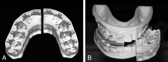
The digital setup was exported into Appliance Designer software (3Shape) to design the indirect bonding transfer trays digitally. They were subsequently 3D-printed on a Carbon digital light synthesis printer (Carbon, Redwood City, CA) using Fotodent IBT 385 nm biocompatible resin (Dreve Dentamid, Unna, Germany). Each tray was sectioned at the midline. Brackets were manually installed in their respective wells and the trays were then tried onto 3D-printed models of the dentition to ensure proper fit (Figure 1).
Figure 1.
3D-printed indirect bonding trays. (A) Intaglio view with brackets installed. (B) Indirect bonding tray tried onto 3D-printed model.
Bonding Procedure
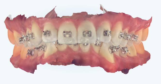
A total of 410 brackets were bonded to incisors, canines, and premolars of both dental arches by a single operator. The average time from scan acquisition to bonding was 2 weeks. The teeth were pumiced, etched using 37% phosphoric acid for 20 seconds, rinsed, and dried. Assure Plus primer (Reliance Orthodontic Products, Itasca, IL) was applied to the tooth surfaces and Transbond XT light-curing adhesive (3M) to the bracket bases. Each tray was seated using light finger pressure on the occlusal surface. The adhesive was then light-cured for 40 seconds per tooth. After tray removal, excess adhesive was removed from around the brackets with a carbide bur on a slow-speed handpiece. Any immediate bond failures were recorded, and an intraoral scan was taken using the iTero Element scanner to capture the final position of the brackets on the teeth (Figure 2). The resulting digital model, referred to as the postbonding model, was exported in STL format and used for comparison to the digital setup.
Figure 2.
Postbonding intraoral scan of the dentition.
Data Acquisition
The digital setup and postbonding model for each patient were digitally superimposed using best-fit methods using VisionX Compare software (VisionX, Edina, MN). To ensure that superimposition was based only on tooth-surface features, soft tissue and brackets were eliminated from the postbonding models (Figure 3). Initial registration was completed using a six-point match based on the buccal cusp tips of the premolars and canines. An iterative closest point matching algorithm was used to achieve surface feature-based, best-fit superimposition. To assign the position of each bracket in space, four consistent datums were identified on the surface of each bracket in the upper left, lower left, upper right, and lower right corners of the bracket base (Figure 4). An X-Y-Z coordinate system was automatically created based on these datums. In some cases, the quality of the postbonding scan prohibited the identification of the landmark datums. Such brackets were discarded from analysis due to what is referred to as a scan error.
Figure 3.
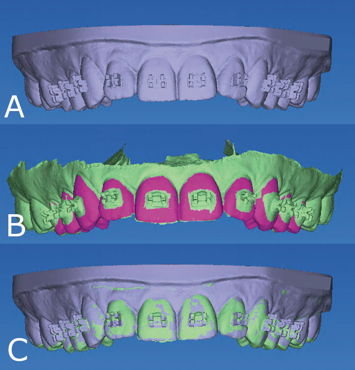
Digital models and superimposition. (A) Digital setup model with virtually positioned brackets. (B) Prepared postbonding model; highlighted fuchsia structure represents tooth surface used for superimposition. (C) Superimposed best-fit digital setup model (gray) and postbonding model (green).
Figure 4.
Bracket coordinate generation. (A) Datum placement for bracket coordinate identification in the corners of the inner portion of the bracket base at the intersection with the tie wings. (B) Automatically generated X-Y-Z bracket coordinate systems. Digital setup coordinate system (gray) and postbonding coordinate system (green) viewed in overlay.
For each corresponding bracket pair in the digital setup and postbonding models, the software computed the positional discrepancies in each dimension automatically with respect to six dimensions of tooth movement, including mesiodistal, buccolingual, and occlusogingival translation, and torque, tip, and rotation. In this process, the digital setup model was considered the reference and the postbonding model was considered the comparison. Computed differences described the magnitude and direction of the discrepancy, which was designated by the sign of the value, either positive or negative (Table 1).
Table 1.
Directionality of Bonding Error
| Dimension |
Measure Type |
Positive (+) |
Negative (−) |
| Mesiodistal | Linear (mm) | Mesial translation | Distal translation |
| Buccolingual | Linear (mm) | Buccal translation | Lingual translation |
| Occlusogingival | Linear (mm) | Occlusal translation | Gingival translation |
| Torque | Angular (°) | Buccal crown torque | Lingual crown torque |
| Tip | Angular (°) | Mesial crown tip | Distal crown tip |
| Rotation | Angular (°) | Mesial-in | Mesial-out |
The same operator remeasured a total of 65 brackets from seven randomly selected arches after a wash-out period of 2 weeks. Repeatability was assessed as the difference of measurements on replicate samples using the method described by Bland and Altman.8
Statistical Analysis
To eliminate the possibility that summation of positive and negative discrepancy values would negate one another, absolute values of each individual discrepancy were calculated. Mean values and standard deviations for each dimension were calculated for the composite sample and for each tooth type. Discrepancy values for each dimension were compared independently for maxillary and mandibular arches, and between right and left teeth using two-sample t-tests. Right-left comparison demonstrated equal distribution of values for each dimension, so right and left analogous tooth types within each arch were combined for further analysis.
One-tailed t-tests were performed on the absolute value of the discrepancy measurements in each dimension to determine whether the mean transfer error was statistically within limits of 0.5 mm for linear measurements and 2° for angular measurements (H0: μ ≥ 0.5 mm; H0: μ ≥ 2°). P values of less than .05 indicated differences within the limits of 0.5 mm for linear measurements and 2° for angular measurements. These limits were selected because they represent accepted professional standards. The American Board of Orthodontics deducts points for teeth that deviate 0.5 mm or more from proper alignment or alignment of marginal ridges.9 A crown-tip positioning error of 2° causes a marginal ridge discrepancy of 0.5 mm in an average-sized molar.
The frequencies of bracket-position discrepancies for each tooth type within and outside of the acceptable thresholds were calculated for the total sample, for each tooth type, and for each tooth type within a given arch. The frequencies of directional errors were calculated for the total sample and for each tooth type. All analyses were performed using SAS 9.4 (SAS Institute, Cary, NC) with the level of statistical significance set to α = 0.05.
RESULTS
Bland-Altman analyses yielded mean differences ranging from −0.002 mm to 0.006 mm for linear measurements, and from −0.103° to 0.409° for angular measurements (Table 2). Of the 410 brackets used, 19 failed to adhere during the bonding procedure, resulting in a bond failure rate of 4.63%. In nearly all bond failure cases, the bracket remained in the transfer tray, and the adhesive remained on the dentition. An additional 28 brackets were excluded as what were referred to as scan errors. The remaining 363 brackets were evaluated for transfer accuracy.
Table 2.
Bland-Altman Analyses Performed to Assess Repeatability for Each Dimension of Tooth Movementa
| Dimension |
n |
Mean |
Lower 95% CL for Mean |
Upper 95% CL for Mean |
| Mesiodistal (mm) | 65 | −0.002 | −0.009 | 0.004 |
| Buccolingual (mm) | 65 | 0.006 | −0.002 | 0.013 |
| Occlusogingival (mm) | 65 | −0.002 | −0.011 | 0.006 |
| Torque (°) | 65 | 0.409 | −0.049 | 0.867 |
| Tip (°) | 65 | −0.087 | −0.512 | 0.337 |
| Rotation (°) | 65 | −0.103 | −0.641 | 0.435 |
CL indicates confidence level; n, number of brackets used for analysis.
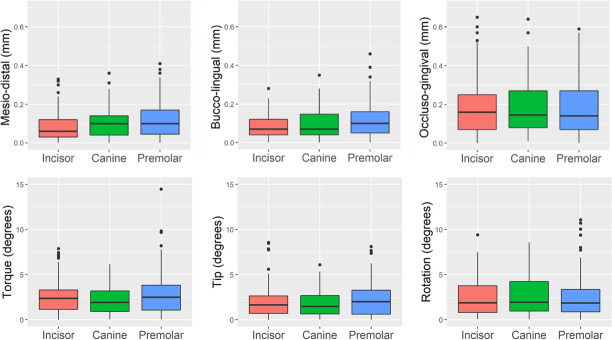
The means and standard deviations of the linear and angular bracket-position differences are shown in Table 3 and Figure 5. For the total sample, the linear transfer errors were 0.10 ± 0.08 mm, 0.10 ± 0.07 mm, and 0.18 ± 0.14 mm for the mesiodistal, buccolingual, and occlusogingival dimensions, respectively. The angular transfer errors for the total sample were 2.55 ± 1.98°, 2.01 ± 1.66°, and 2.47 ± 2.09° for torque, tip, and rotation, respectively. When comparing the discrepancy between upper and lower teeth within a given linear dimension, there was consistently a greater magnitude of error in the buccolingual dimension for the lower arch compared to the upper arch in all tooth types. No other clear patterns were noted. One-sided t-tests reached statistical significance (P < .05) for all linear dimensions in all tooth types, indicating that the brackets were transferred within the acceptable limit of 0.5 mm in the mesiodistal, buccolingual, and occlusogingival dimensions, regardless of tooth type or arch. In contrast, one-sided t-tests did not reach statistical significance (P > .05) for all angular dimensions in all tooth types except maxillary canine tip. This suggests that, aside from maxillary canine tip, the difference in torque, tip, and rotation of the final bracket position was outside of the acceptable limit of 2°.
Table 3.
Differences between Postbonding Bracket Position and Digital Setupa,b
| Tooth Type |
n |
Dimension |
|||||
| MD (mm) |
BL (mm) |
OG (mm) |
Torque (°) |
Tip (°) |
Rotation (°) |
||
| Incisor | 150 | 0.087 ± 0.074c | 0.083 ± 0.059c | 0.179 ± 0.136c | 2.493 ± 1.790 | 1.961 ± 1.724 | 2.393 ± 1.908 |
| U Incisor | 72 | 0.095 ± 0.075c | 0.071 ± 0.053c | 0.165 ± 0.138c | 2.273 ± 1.559 | 1.750 ± 1.818 | 1.902 ± 1.623 |
| L Incisor | 78 | 0.080 ± 0.072c | 0.094 ± 0.062c | 0.193 ± 0.134c | 2.696 ± 1.968 | 2.155 ± 1.621 | 2.847 ± 2.044 |
| Canine | 74 | 0.103 ± 0.076c | 0.100 ± 0.079c | 0.180 ± 0.134c | 2.154 ± 1.469 | 1.780 ± 1.304 | 2.692 ± 2.203 |
| U Canine | 38 | 0.117 ± 0.082c | 0.081 ± 0.064c | 0.175 ± 0.147c | 2.028 ± 1.486 | 1.522 ± 1.164c | 2.989 ± 2.246 |
| L Canine | 36 | 0.087 ± 0.067c | 0.121 ± 0.089c | 0.185 ± 0.120c | 2.286 ± 1.460 | 2.052 ± 1.401 | 2.378 ± 2.144 |
| Premolar | 139 | 0.116 ± 0.089c | 0.114 ± 0.083c | 0.182 ± 0.149c | 2.824 ± 2.359 | 2.182 ± 1.741 | 2.439 ± 2.218 |
| U Premolar | 69 | 0.142 ± 0.094c | 0.094 ± 0.067c | 0.182 ± 0.134c | 2.472 ± 1.974 | 1.777 ± 1.390 | 2.733 ± 2.268 |
| L Premolar | 70 | 0.091 ± 0.077c | 0.133 ± 0.092c | 0.182 ± 0.164c | 3.171 ± 2.654 | 2.582 ± 1.958 | 2.148 ± 2.144 |
| Total | 363 | 0.101 ± 0.081c | 0.098 ± 0.074c | 0.181 ± 0.140c | 2.550 ± 1.984 | 2.009 ± 1.657 | 2.471 ± 2.089 |
Results are mean values ± standard deviations. All values are absolute values.
n, number of each tooth type used for analysis; BL indicates bucco-lingual; MD, mesiodistal; OG, occlusogingival.
The transferred bracket position is within the selected limits of 0.5 mm for linear measurements and 2° for angular measurements.
Figure 5.
Box-and-whisker plots of discrepancies between planned and actual bracket positions for the three tooth types in six dimensions. The centerline denotes the median. The upper and lower borders of the box represent the third and the first quartile, respectively. The vertical lines mark the third quartile plus 1.5 times the interquartile range and the first quartile minus 1.5 times the interquartile range, respectively. Values beyond these bounds are outliers.
The frequencies of bracket position within the acceptable limits of 0.5 mm and 2° are shown in Table 4. Frequencies within these limits ranged from 96.4% to 100% for the linear dimensions and from 46.0% to 57.0% for the angular dimensions in the composite sample. Overall, the transfer accuracy was highest for mesiodistal and buccolingual bracket placement (both 100%), and lowest for torque (46.0%). The frequencies of directional biases are shown in Table 5. In the buccolingual dimension, the final bracket position was biased toward the buccal in 67.5% of the brackets.
Table 4.
Frequency of Postbonding Bracket Position Within the Selected Limits of Acceptabilitya,b
| Tooth Type |
n |
Dimension |
|||||
| MD |
BL |
OG |
Torque |
Tip |
Rotation |
||
| Incisor | 150 | 150 (100) | 150 (100) | 145 (96.7) | 68 (45.3) | 92 (61.3) | 77 (51.3) |
| U incisor | 72 | 72 (100) | 72 (100) | 70 (97.2) | 35 (48.6) | 50 (69.4) | 45 (62.5) |
| L incisor | 78 | 78 (100) | 78 (100) | 75 (96.2) | 33 (42.3) | 42 (53.8) | 32 (41.0) |
| Canine | 74 | 74 (100) | 74 (100) | 71 (95.9) | 39 (52.7) | 46 (62.2) | 38 (51.4) |
| U canine | 38 | 38 (100) | 38 (100) | 36 (94.7) | 22 (57.9) | 26 (68.4) | 18 (47.4) |
| L canine | 36 | 36 (100) | 36 (100) | 35 (97.2) | 17 (47.2) | 20 (55.6) | 20 (55.6) |
| Premolar | 139 | 139 (100) | 139 (100) | 134 (96.4) | 60 (43.2) | 69 (49.6) | 74 (53.2) |
| U premolar | 69 | 69 (100) | 69 (100) | 68 (98.6) | 32 (46.4) | 39 (56.5) | 31 (44.9) |
| L premolar | 70 | 70 (100) | 70 (100) | 66 (94.2) | 28 (40.0) | 30 (42.9) | 43 (61.4) |
| Total | 363 | 363 (100) | 363 (100) | 350 (96.4) | 167 (46.0) | 207 (57.0) | 189 (52.1) |
n, number of brackets used for analysis; BL indicates bucco-lingual; MD, mesiodistal; OG, occlusogingival.
Results are expressed as count (percentage).
Table 5.
Frequency of Directional Bias Resulting from the Indirect Bonding Methoda,b
| Tooth Type |
n |
Dimension |
|||||||||||
| Mesiodistal |
Buccolingual |
Occlusogingival |
Torque |
Tip |
Rotation |
||||||||
| Mesial |
Distal |
Buccal |
Lingual |
Occlusal |
Gingival |
BCT |
LCT |
Mesial |
Distal |
M-in |
M-out |
||
| Incisor | 150 | 38.7 | 61.3 | 52.0 | 48.0 | 49.3 | 50.7 | 48.0 | 52.0 | 57.3 | 42.7 | 54.7 | 45.3 |
| Canine | 74 | 68.9 | 31.1 | 74.3 | 25.7 | 44.6 | 55.4 | 44.5 | 55.4 | 54.1 | 46.0 | 56.8 | 43.2 |
| Premolar | 139 | 71.2 | 28.8 | 80.6 | 19.4 | 66.2 | 33.8 | 25.9 | 74.1 | 38.1 | 61.9 | 54.7 | 45.3 |
| Total | 363 | 57.3 | 42.7 | 67.5 | 32.5 | 54.3 | 45.2 | 38.8 | 61.2 | 49.3 | 50.7 | 55.1 | 44.9 |
n, number of brackets used for analysis. BCT indicates buccal crown torque; LCT, lingual crown torque; M-in, mesial-in; M-out, mesial-out.
Results are expressed as percentages.
DISCUSSION
The high frequencies of bracket position within acceptable limits and the small mean errors, approximately one-tenth of a millimeter in most cases, suggests that the studied indirect bonding trays had a high transfer accuracy in the linear dimensions. There was consistently a greater magnitude of error in the buccolingual dimension for the lower arch compared to the upper arch in all tooth types. This may have been due to more variable pressure applied to seat the lower trays. The tray thickness, access, and moisture control more often presented challenges for the operator in the lower arch. In contrast, the mean transfer accuracy in the angular dimensions was statistically outside of the acceptable limit of 2° for all tooth types with the exception of maxillary canines. Only approximately one-half of the brackets were positioned within the acceptable limit for any given angular dimension, suggesting poor transfer accuracy in the angular dimensions.
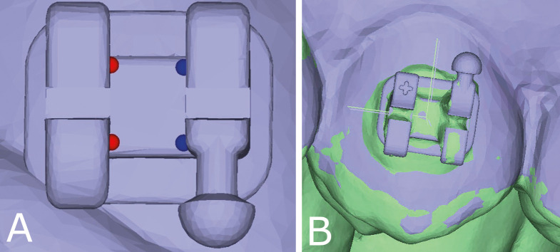
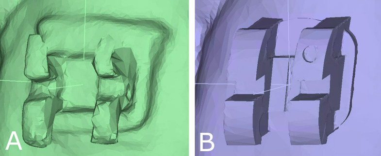
However, the results for the angular dimensions must be interpreted with caution. First, the Bland-Altman analysis showed a greater difference between the upper and lower limits of agreement and a larger bias for the angular dimensions compared to the linear dimensions when repeat measurements were performed, which raised questions regarding the ability to reproduce angular measurements on the scans. Second, some of the bracket surfaces upon which the datum points for coordinate generation fell appeared to be multiplanar on the postbonding scans (Figure 6). This contrasted with the smooth virtual brackets on the prebonding models. While a multiplanar surface would have minimal effect on differences in the linear dimensions, it could impact angular dimensions considerably, as datums placed on an angled plane in the postbonding scan would result in an inaccurate coordinate system orientation, creating the illusion of large angular discrepancies.
Figure 6.
Digital model quality. Example of the same bracket. (A) Postbonding scan. (B) Prebonding virtual model with bracket selected from bracket library.
The apparent multiplanar surfaces on the postbonding scans could have been the result of image distortion caused by diffuse light reflection during scanning of the metal brackets with the iTero scanner.10 Although this scanner is one of the most accurate of the commercially available intraoral scanners with the sharpest images compared to other scanners in an in vitro study,11 the in vivo situation is much different, where moisture and accessibility are factors. In an in vivo study on scanner accuracy on bonded dentition, images were distorted within 0.5 mm of brackets with good accuracy of the scans on the tooth surfaces greater than 0.5 mm away from the brackets.10 This supports the idea that, although the postbonding scans with brackets in the present study were accurate enough for superimposition on tooth structure, distortions were present on the reflective bracket surfaces, negatively affecting the angular measurements.
Interestingly, several in vitro studies with 3D-printed trays,12 3D-printed jigs,13 and traditional transfer trays14 also demonstrated better linear transfer accuracy compared to angular transfer accuracy. For instance, Niu et al. reported low transfer accuracy in the angular dimensions, with acceptable bracket positioning only in 57%, 51%, and 85% of the cases for tip, torque, and rotation, respectively.12 Similarly, Kim et al. reported high transfer accuracy in the linear dimensions (93%–100% within acceptable limits) and low transfer accuracy in the angular dimensions (27%–57% within acceptable limits) using 3D-printed jigs in vitro.13 Schmid et al. had a similar pattern of findings using traditional methods.14
Niu et al. attributed the high transfer accuracy in the linear dimensions to the relatively rigid printed tray material and the low angular transfer accuracy to tray design, which provided relief for hooks and undercuts, potentially weakening angular control of bracket positioning.12 By this rationale, thicker or more rigid trays could lead to enhanced angular control. However, this would likely come with the tradeoff of difficulty removing the trays and a potential for higher bond failures. Although the present bond failure rate of 4.63% was similar to that reported in the literature for 3D-printed indirect bonding trays in vivo,15 bond failures were almost invariably a result of bracket engulfment in the tray material. In nearly all instances of bond failure, the gingival tie wings were covered by tray material, requiring considerable force for tray removal. Shorter trimming and reduced thickness of the trays could conceivably reduce the bond failure rate but may come at the expense of poorer transfer accuracy due to less rigidity.
While the similarities between the present results and those of in vitro studies are interesting, it is more valuable to compare them to another in vivo study evaluating 3D-printed transfer trays. Similar to the present study, Chaudhary et al. found low magnitudes and rates of transfer errors in the linear dimensions.16 With the exception of nine brackets, all of their positional discrepancies were within 0.25 mm for linear dimensions. However, in sharp contrast to the present findings, Chaudhary et al. measured the greatest transfer accuracy in the angular dimensions, with all brackets placed within a stringent acceptability limit of 1°.16 This difference could have been due to differences in scan quality, tray design or, at least in part, differences in the study subjects evaluated, who were at least 17 years old and had milder malocclusions than those in the present study. The influence of gingival margin position (which is typically more occlusally positioned in younger patients) and degree of crowding on tray adaptation and transfer accuracy cannot be overlooked.
The present study also found a modest directional bias of the transferred brackets toward the buccal compared to the intended position. This was consistent with studies using traditional indirect bonding trays7 and likely a consequence of the adhesive layer between the tooth surface and the bracket base. Notably, the present study did not find a consistent bias in the other linear and angular dimensions.
A potential limitation of the present study was the apparent lack of standardization caused by the use of two different bracket systems. However, clinicians expect 3D-printed indirect bonding trays to work with a variety of brackets. Their application to different bracket systems therefore reflects a real-world situation.
CONCLUSIONS
Indirect bonding using 3D-printed trays transfers the planned bracket position to the patient's dentition with a high positional accuracy in the mesiodistal, buccolingual, and occlusogingival dimensions while questions remain for torque, tip, and rotation.
The frequency of bracket transfer error is approximately the same for all tooth types.
The transferred bracket position demonstrates a modest bias toward the buccal.
ACKNOWLEDGMENTS
The authors are grateful to Partners Dental Studio for 3D printing the indirect bonding trays and to Mike Marshall for developing the custom software tool used in this study.
REFERENCES
- 1.Silverman E, Cohen M, Gianelly AA, Dietz VS. A universal direct bonding system for both metal and plastic brackets. Am J Orthod . 1972;62:236–244. doi: 10.1016/s0002-9416(72)90264-3. [DOI] [PubMed] [Google Scholar]
- 2.Koga M, Watanabe K, Koga T. Quick Indirect Bonding System (Quick IDBS): an indirect bonding technique using a double-silicone bracket transfer tray. Semin Orthod . 2007;13:11–18. [Google Scholar]
- 3.Nojima LI, Araújo AS, Alves M., Júnior Indirect orthodontic bonding–A modified technique for improved efficiency and precision. Dental Press J Orthod . 2015;20:109–117. doi: 10.1590/2176-9451.20.3.109-117.sar. [DOI] [PMC free article] [PubMed] [Google Scholar]
- 4.Christensen LR, Cope JB. Digital technology for indirect bonding. Semin Orthod . 2018;24:451–460. [Google Scholar]
- 5.Spitz A, Gribel BF, Marassi C. CAD/CAM technology for digital indirect bonding. J Clin Orthod . 2018;52:621–628. [PubMed] [Google Scholar]
- 6.Layman B. Digital bracket placement for indirect bonding. J Clin Orthod . 2019;53:387–396. [PubMed] [Google Scholar]
- 7.Grünheid T, Lee MS, Larson BE. Transfer accuracy of vinyl polysiloxane trays for indirect bonding. Angle Orthod . 2016;86:468–474. doi: 10.2319/042415-279.1. [DOI] [PMC free article] [PubMed] [Google Scholar]
- 8.Bland JM, Altman DG. Statistical methods for assessing agreement between two methods of clinical measurement. Lancet . 1986;1:307–310. [PubMed] [Google Scholar]
- 9.Casko JS, Vaden JL, Kokich VG, et al. Objective grading system for dental casts and panoramic radiographs. Am J Orthod Dentofac Orthop . 1998;114:589–599. doi: 10.1016/s0889-5406(98)70179-9. [DOI] [PubMed] [Google Scholar]
- 10.Kang SJ, Kee YJ, Lee KC. Effect of the presence of orthodontic brackets on intraoral scans. Angle Orthod . 2021;91:98–104. doi: 10.2319/040420-254.1. [DOI] [PMC free article] [PubMed] [Google Scholar]
- 11.Park JM, Choi SA, Myung JY, Chun YS, Kim M. Impact of orthodontic brackets on the intraoral scan data accuracy. Biomed Res Int . 2016;2016:5075182. doi: 10.1155/2016/5075182. [DOI] [PMC free article] [PubMed] [Google Scholar]
- 12.Niu Y, Zeng Y, Zhang Z, Xu W, Xiao L. Comparison of the transfer accuracy of two digital indirect bonding trays for labial bracket bonding. Angle Orthod . 2021;91:67–73. doi: 10.2319/013120-70.1. [DOI] [PMC free article] [PubMed] [Google Scholar]
- 13.Kim J, Chun YS, Kim M. Accuracy of bracket positions with a CAD/CAM indirect bonding system in posterior teeth with different cusp heights. Am J Orthod Dentofac Orthop . 2018;153:298–307. doi: 10.1016/j.ajodo.2017.06.017. [DOI] [PubMed] [Google Scholar]
- 14.Schmid J, Brenner D, Recheis W, Hofer-Picout P, Brenner M, Crismani AG. Transfer accuracy of two indirect bonding techniques–an in vitro study with 3D scanned models. Eur J Orthod . 2018;40:549–555. doi: 10.1093/ejo/cjy006. [DOI] [PubMed] [Google Scholar]
- 15.Czolgosz I, Cattaneo PM, Cornelis MA. Computer-aided indirect bonding versus traditional direct bonding of orthodontic brackets: bonding time, immediate bonding failures, and cost-minimization. A randomized controlled trial. Eur J Orthod . 2021;43:144–151. doi: 10.1093/ejo/cjaa045. [DOI] [PubMed] [Google Scholar]
- 16.Chaudhary V, Batra P, Sharma K, Raghavan S, Gandhi V, Srivastava A. A comparative assessment of transfer accuracy of two indirect bonding techniques in patients undergoing fixed mechanotherapy: A randomised clinical trial. J Orthod . 2021;48:13–23. doi: 10.1177/1465312520968571. [DOI] [PubMed] [Google Scholar]


