Abstract
Electron transport layers (ETLs) play a fundamental role in perovskite solar cells (PSCs) through charge extraction. Here, we developed flexible PSCs on 12 different kinds of ETLs based on SnO2. We show that ETLs need to be specifically developed for plastic substrates in order to attain 15% efficient flexible cells. Recipes developed for glass substrates do not typically transfer directly. Among all the ETLs, ZnO/SnO2 double layers delivered the highest average power conversion efficiency of 14.6% (best cell 14.8%), 39% higher than that of flexible cells of the same batch based on SnO2-only ETLs. However, the cells with a single ETL made of SnO2 nanoparticles were found to be more stable as well as more efficient and reproducible than SnO2 formed from a liquid precursor (SnO2-LP). We aimed at increasing the understanding of what makes a good ETL on polyethylene terephthalate (PET) substrates. More so than ensuring electron transport (as seen from on-current and series resistance analysis), delivering high shunt resistances (RSH) and lower recombination currents (Ioff) is key to obtain high efficiency. In fact, RSH of PSCs fabricated on glass was twice as large, and Ioff was 76% lower in relative terms, on average, than those on PET, indicating considerably better blocking behavior of ETLs on glass, which to a large extent explains the differences in average PCE (+29% in relative terms for glass vs PET) between these two types of devices. Importantly, we also found a clear trend for all ETLs and for different substrates between the wetting behavior of each surface and the final performance of the device, with efficiencies increasing with lower contact angles (ranging between ∼50 and 80°). Better wetting, with average contact angles being lower by 25% on glass versus PET, was conducive to delivering higher-quality layers and interfaces. This cognizance can help further optimize flexible devices and close the efficiency gap that still exists with their glass counterparts.
Keywords: flexible perovskite solar cells, substrates, rigid perovskite solar cells, solution-processed electron transport layer, SnO2 layer, ZnO/SnO2 double layer, flexible versus rigid, polyethylene terephthalate
1. Introduction
Perovskite solar cells (PSCs) have evoked tremendous interest in solar energy researchers. PSCs combine high-efficiency and high-throughput manufacturing via solution processing.1 Whereas the main substrate has largely been glass, development of PSCs on flexible substrates has recently accelerated. This is because they are light, flexible, and processed at low-temperatures at very low cost,2 even via roll-to-roll manufacturing,3 and can be easily integrated in many objects conformally for both outdoor and indoor operation.4−7
In general, the photoactive perovskite layer (i) is sandwiched between an (n) electron transport layer (ETL) and a (p) hole transport layer (HTL). The ETL, in n–i–p architectures, plays a vital role in achieving high-performance solar cells: it promotes the collection of photogenerated electrons from the perovskite layer to the bottom electrode as well as suppressing recombination.8 The main ETLs for n–i–p architectures are largely consisted of metal oxides such as TiO2,9 ZnO,10,11 and SnO2.12,13
For flexible PSCs (FPSCs), deposition of thin-film ETLs must be carried out at low temperatures, that is, below 150 °C.14 Wang et al. developed room-temperature-processed WOx as ETL achieving a power conversion efficiency (PCE) of 15.85%.15 By introducing SnS2 as ETL, Chu et al. reported a power conversion efficiency of 13.2% with a negligible hysteresis effect in FPSCs.16 Low-temperature-processed Zn2SnO4 nanoparticles (NPs) have also been shown to be a good ETL for efficient FPSCs.17−19 Liu and Kelly demonstrated a PCE with 10% using ZnO NP as ETL.20 However, ZnO is found to accelerate the thermal degradation of perovskite films.21,22
SnO2 has become in recent years the prime candidate as ETL in FPSCs since it can be deposited and processed at low temperatures on plastic substrates,23,24 even though its performance in some reports can still suffer from large densities of surface trap states, resulting in photocurrent hysteresis and poor fill factors (FFs).25,26 In fact, SnO2 can be deposited via different techniques, from sputtering to solution processing of precursor solutions or NP dispersions.27 There have been many reports on PSCs, mainly on rigid glass substrates, which applied interface treatment to SnO2 with materials such as polyelectrolytes,28 H2O,29 and KOH30 or proposed the addition of a second layer of metal oxide either over or underneath SnO2. For example, solid-state ionic liquids (SS-ILs) have been applied to function as independent ETLs31,32 or used to modify another ETL such as TiO2.31 Bu et al. have introduced potassium treatment as a passivation strategy for SnO2 ETLs in order to suppress the hysteresis effect and the surface defects of the perovskite.30 By introducing a ZnXSnXO/SnO2 bilayer ETL, Thambidurai et al. demonstrated an efficiency of 19% on rigid PSCs.33 The ZnS interlayer improved the efficiency and stability of PSCs via passivation of the ZnO surface and reduction of interfacial charge recombination.34 Chung et al. achieved record efficiency on flexible cells using a porous-planar structure as an ETL.35 A ZnO–SnO2-cascaded ETL was employed to improve the interface stability and efficiency of PSCs.36 Dagar et al. developed all-solution-processed ETLs: SnO2/meso-TiO2 bilayers on flexible substrates and SnO2/MgO, SnO2/Al2O3 bilayers on rigid substrates, improving PCEs significantly7,37,38 by enhancing wettability, rectification ratios, and shunt resistances.37,38 The ETL overlayer has also been shown to reduce the work function of the composite electrode thus helping improve electron extraction.39
Most of these works have been carried out on glass substrates and have not been investigated on flexible polyethylene terephthalate/indium tin oxide (PET/ITO) substrates. The morphological, chemical, and/or wetting properties of the PET/ITO substrates can be very different from those of glass.28,40,41 Thus, the quality and performance of ETLs will generally differ when transferring recipes for glass substrates to flexible substrates. Here, we carried out a systematic investigation of many different strategies and materials for SnO2-based ETLs, which can be summarized as follows: single-layer SnO2, both from NP dispersion (SnO2-NP) and from liquid precursors (SnO2-LPs); single-layer SnO2 with H2O and KOH surface treatments; and double-layer ETLs, that is, SnO2/SS-IL, SnO2/mp-TiO2, SnO2/MgO, MgO/SnO2, SnO2/Al2O3, and ZnO/SnO2. Whereas some strategies worked on glass, improving the PCE compared to the control devices, as described in the literature, there were no significant enhancements when transferred to flexible substrates. We instead found that double layers of ZnO/SnO2 led to a significant enhancement in efficiency in flexible cells. Furthermore, SnO2 NPs worked considerably better and more reproducibly compared to SnO2 grown from a liquid precursor. SnO2-NP ETLs also led to the more stable FPSCs. Importantly, the systematic investigation on so many different cells and cell types differing only by the type of ETL enabled us to gain a deeper understanding of what makes a good ETL for FPSCs and the differences compared to those manufactured on glass, relating to parameters such as series and shunt resistances, recombination, injection currents, and wettability, which limit the efficiency achievable on this type of more challenging substrate. Quantifiable differences were found for these parameters in order to achieve high-efficiency ETLs for FPSCs.
2. Experimental Section
2.1. Materials
Zinc oxide dispersion, tin chloride (SnCl2·2H2O) dehydrate, Al2O3 (aluminum oxide) NPs with <50 nm particle size, magnesium acetate tetrahydrate [(CH3COO)2Mg·4H2O], lead(II) bromide (PbBr2), cesium iodide (CsI), tert-butylpyridine (TBP), Li bis(trifluoromethanesulfonyl)imide (Li-TFSI), potassium hydroxide solution (KOH), and solvents dimethyl sulfoxide (DMSO anhydrous, ≥99.9%), N,N-dimethylformamide (DMF anhydrous, 99.8%), diethyl ether (99.0%), ethanol (99.8%), and 2-propanol anhydrous 99.5% were purchased from Sigma-Aldrich. Tin(IV) oxide 15% in H2O colloidal dispersion and 1-benzyl-3-methylimidazolium chloride (IL1) were purchased from Alpha Aesar. 1-Butyl-3-methylimidazolium tetrafluoroborate (IL2) was purchased from Acros Organics. Lead(II) iodide (PbI2) (99.99%, trace metal basis) was purchased from TCI Deutschland GmbH. Formamidinium iodide (FAI) methylammonium bromide (MABr), and methylammonium iodide (MAI) were purchased from GreatCell Solar. 18NR-T titania paste and cobalt salt (III) FK209 TFSI (98%) were purchased from Dyesol Limited. 2,2′,7,7′-Tetrakis-(N,N-di-p-methoxyphenylamine)-9,9′-spirobifluorene (spiro-OMeTAD) (≥99.8%) was purchased from Borun New Material Technology Co., Ltd.
2.2. Device Fabrication
PET/ITO (125 μm thickness, 15 Ω sq–1 Flexvue) and glass/ITO (Kintec 8 Ω sq–1) were cut mechanically to obtain 2.5 × 2.5 cm substrates. The ITO electrode was patterned using a CO2 laser and raster scanning laser. The substrates were cleaned in water and soap, isopropanol, and water for 10 min each using an ultrasonic bath, followed by drying with compressed air. The architecture used for the fabrication of our FPSCs was PET/ITO/ETL/perovskite/spiro-OMeTAD/Au and glass/ITO/ETL/perovskite/spiro-OMeTAD/Au for our rigid ones. To enhance the wettability of the ITO electrode, the substrates were treated with UV irradiation for 10 min. A ZnO ETL was deposited on the PET/ITO substrate by a spin coating process (3000 rpm, 30 s) using ZnO NP dispersion in ethanol (Sigma-Aldrich, 40 wt %) which was further diluted with ethanol in order to obtain 4 wt % concentration. The ZnO film was annealed at 100 °C for 1 h, followed by a UV irradiation treatment for 10 min. Afterward, SnO2 ETL (15% in H2O colloidal dispersion, Alfa Aesar) was spin coated over the ZnO layer at a spin speed of 6000 rpm for 35 s obtaining a ∼60 nm thick ZnO/SnO2 bilayer, with a ∼40 nm thick SnO2 layer. SnO2 was also annealed at 100 °C for 1 h and further exposed to a UV irradiation treatment for 10 min. For SnO2-LP, the ETL was deposited by spin coating a 0.1 M precursor solution of SnCl2/2H2O in ethanol at 1500 rpm for 30 s, followed by a second step at 2500 rpm for 30 s; films were annealed at 150 °C for 1 h. For the SnO2-NP ETL modified by H2O and KOH interface treatments, the ETL was first dipped in H2O at 90 °C for 1 h (SnO2–H2O), the second treatment was the spin coating of 0.01 M KOH over the SnO2 layer (SnO2/KOH), and finally the last treatment was the combination of the previous two treatments, that is, dipping in H2O at 90 °C for 1 h and then spin coating of 0.01 M KOH (SnO2–H2O/KOH). The ionic-liquid ETLs were deposited by spin coating a 0.3 wt % of IL1 in isopropanol and a 0.3 wt % of IL2 in methanol at 5000 rpm for 60 s and 4000 rpm for 60 s, respectively. TiO2, MgO, and Al2O3 double-layer ETLs were deposited following the optimized procedure reported previously by Dagar et al.7,37,38
The triple cation perovskite solution was prepared by dissolving PbI2, FAI, PbBr2, MABr, and CsI in DMF/DMSO mixed solvents (7:6:2:4 v/v). After stirring overnight at room temperature, the perovskite solution was spin coated by means of a two-step process at 1000 rpm for 10 s with five acceleration steps, followed by 5000 rpm for 30 s with two acceleration steps. During the second step, 150 μL of chlorobenzene was poured on the spinning substrate 7 s prior to the end of the process. The perovskite films were annealed at 100° C for 1 h inside a nitrogen-filled glovebox. In case of cells based on SnO2-LP ETL, the perovskite layer was MAPI as this type of perovskite worked better with SnO2-LP.7 The MAPbI3 solution was prepared by dissolving PbI2 and MAI in a 1:1 molar ratio in a solvent mixture composed of DMF/DMSO (9:1, v/v) to obtain a final concentration of 1.4 M. The same spin-coating process of triple cation perovskite was used, but instead of CB, 0.7 mL of diethyl ether was dropped on the rotating substrate. Perovskite films were annealed at 50 °C for 2 min and 100 °C for 10 min; the process was carried out in air.
For the deposition of the HTL, spiro-OMeTAD was dissolved in chlorobenzene at a concentration of 73.5 mg/mL and doped with TBP (26.77 μL/mL), Li-TFSI (16.6 μL/mL of a 520 mg/mL solution in acetonitrile), and cobalt(III) (7.2 μL/mL of a 376 mg/mL solution in acetonitrile). The spiro-OMeTAD solution was spin coated over the perovskite layer at 2000 rpm for 20 s. The thickness of the triple cation perovskite and MAPI perovskites layers was ∼600 nm. The thickness of the HTL was ∼250 nm as measured with a profilometer. Finally, 90 nm gold contacts were thermally evaporated under high vacuum (below 10–6 mbar) through a shadow mask with a 0.16 cm2 area.
2.3. Device Measurements
The electrical measurements at 1 sun (AM1.5G, 100 mW/cm2, 25 °C) were performed at by means of a Keithley 2420 source meter under an ABET sun 2000 solar simulator class A as the light source. During the measurements, the devices were masked with a black tape with a 0.09 cm2 aperture. Dark J–V measurements were carried out with a modular testing platform (Arkeo 4 channel J–V system-Cicci Research s.r.l.) consisting of a high-speed source meter unit (600 K samples/s). For the stability measurements, unencapsulated devices were tested under white light-emitting diodes (LEDs) (4200 K) at 1 equivalent sun under ambient conditions. The MPP was measured via perturb and observed algorithm implemented onto a commercial apparatus (Arkeo-Ariadne, Cicci Research s.r.l.) based on a set of four-wire independent source meters. Energy-dispersive X-ray (EDX) and scanning electron microscopic (SEM) images were captured with a scanning electron microscope (Leo Supra 35) equipped with an INCAx-Sight Oxford Instruments X-EDS.
3. Results and Discussion
We first present a systematic study on flexible substrates that includes 12 different ETL types on PET/ITO and over 160 cells. We will subsequently analyze the more interesting four types of ETLs and carry out, over one simultaneous experiment, a vis-a-vis comparison between devices manufactured on PET and on glass in order to understand and quantify differences between the two types of devices (glass and PET).
3.1. 12 Different ETLs for FPSCs
We fabricated 12 different sets of PSCs on PET/ITO substrates; each with a distinct ETL based on SnO2 as the common material. All incorporate a compact SnO2 ETL deposited by spin coating, some with the addition of another metal oxide and others with a polyelectrolyte or an interface treatment of the SnO2 layer prior to the deposition of the overlaying perovskite film. Stacks were completed with a perovskite active layer, spiro-OMeTAD HTL, and an Au top electrode. All layers except the evaporated metal contact were deposited by solution-processing at low temperatures (<150 °C).
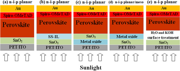
As schematized in Figure 1, there were five different architectures of FPSCs in 12 different material configurations in total that we investigated. The first type (Figure 1a) consisted in PSCs with SnO2 only as ETL. Two different SnO2 ETLs were tested, one based on a liquid precursor (SnO2-LP), deposited by spin coating a SnCl2 solution in ethanol, and the other consisting in a layer of ready-made NPs (SnO2-NP), deposited by spin coating a water-based colloidal dispersion. The second type of configuration (Figure 1b) contained SnO2/SS-LL bilayer ETLs. We tested two types of SS-IL, that is, IL131 and IL2,42 which were spin coated over SnO2. A third configuration (Figure 1c) consisted in bilayers with a second metal oxide layer, that is, ZnO or MgO, deposited on the PET/ITO substrate below the SnO2 ETL. In contrast, in the fourth type of configuration (Figure 1d), the metal oxide layer, that is, MgO, Al2O3, or mesoporous TiO2, was deposited over the SnO2 layer. In the last configuration (Figure 1e), the SnO2 ETL was subjected to three types of interface treatment using H2O and KOH: dipping in H2O (SnO2–H2O), spin coating of KOH over the SnO2 layer (SnO2/KOH), and a combination of the previous two treatments (dipping in water followed by KOH treatment, labeled as SnO2–H2O/KOH). Summarizing, the 12 different ETLs investigated were SnO2-LP, SnO2-NP, SnO2–H2O, SnO2/KOH, SnO2–H2O/KOH, SnO2/IL1, SnO2/IL2, SnO2/mp-TiO2, SnO2/MgO, MgO/SnO2, SnO2/Al2O3, and ZnO/SnO2. For the composite ETLs (configurations b, c, d, and e), the SnO2 ETLs were made out of NPs (i.e., SnO2-NP) since this led to better performance. The symbol “NP” will not be repeated when describing the SnO2-NP for the sake of simplicity.
Figure 1.
Schematic architectures of the FPSC devices investigated.
3.1.1. Efficiency of FPSCs versus ETLs
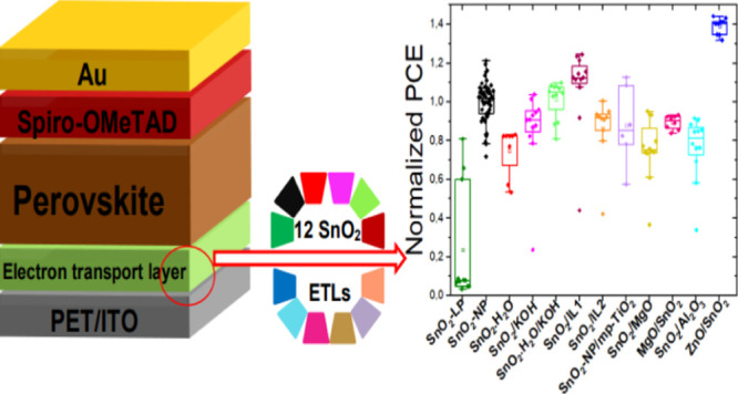
Figure 2 presents the PCEs of the flexible cells fabricated with the 12 different ETLs described above. Different cell configurations were developed over the course of months. Each time, cells with SnO2-NP ETLs were fabricated and used as reference devices. The PCEs of the other configurations are normalized to the average PCE of the reference SnO2-NP cells each time to take into account fluctuations in performance that can occur from batch to batch and over different periods of time (which can be significant). The statistical distribution of the non-normalized PCEs of the 12 different configurations carried out in different batches is reported in Figure S1. Both figures show that ETLs do have a considerable bearing on the power output of the solar cells. When switching from SnO2-LP to SnO2-NP, the average PCE increases by 250%. Not only a boost in performance was observed but the reproducibility also increased dramatically. In fact, the standard deviation was 4.35% in absolute value (143% in relative terms) in the former case but narrowed to 2.2% (down to 23% in relative terms) for SnO2-NP. Thus, the deposition of a SnO2-NP compact layer is much more consistent over different cells and different batches (59 cells were tested for the SnO2-NP case) compared to the liquid precursor formulation. Whereas in glass-based devices, metal oxide bilayers comprising MgO or Al2O3 gave significant boost in efficiency,37,38 this was not the case consistently with flexible devices. Similarly, with the ILs, the boost is not statistically significant for the flexible cells. The only case where a significant improvement in efficiency (39% in relative terms) was observed with respect to the SnO2-NP single layer is represented by the ZnO/SnO2 bilayer.
Figure 2.
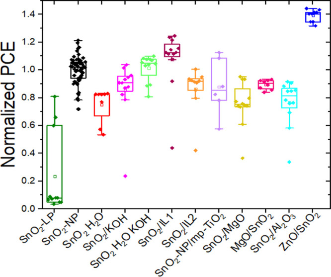
Statistical distribution of PCEs of FPSCs on PET/ITO substrates based on 12 different ETLs, that is, SnO2-LP, SnO2-NP, SnO2–H2O, SnO2/KOH, SnO2–H2O/KOH, SnO2/IL1, SnO2/IL2, SnO2/mp-TiO2, SnO2/MgO, MgO/SnO2, SnO2/Al2O3, and ZnO/SnO2, where IL1 and IL2 are 1-benzyl-3-methylimidazolium chloride and 1-butyl-3-methylimidazolium tetrafluoroborate, respectively. PCE values were normalized by the average efficiency of the reference cell of each batch.
3.1.2. Flexible Cells with SnO2-NP and ZnO/SnO2 ETLs
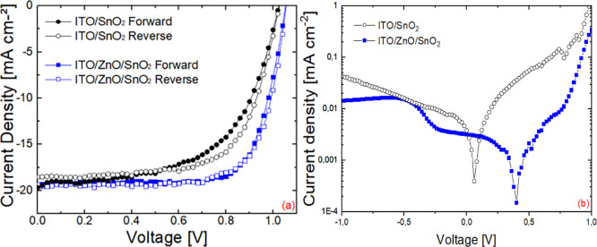
The current density–voltage (J–V) characteristics of the best-performance FPSCs based on SnO2 and ZnO/SnO2 ETLs fabricated simultaneously in the same batch under one sun illumination are shown in Figure 3a. Table 1 lists the average photovoltaic (PV) parameters of the cells at one sun, including short-circuit current (JSC), open-circuit voltage (VOC), fill factor (FF), and PCE. For this particular batch, the flexible devices with a neat layer of SnO2-NP exhibit an average PCE of 10.5%, while the devices with a ZnO/SnO2 bilayer yield an average PCE of 14.6%. Thus, the insertion of the ZnO layer between the ITO cathode and the SnO2 layer was beneficial for the solar cell power output.
Figure 3.
(a) J–V curves of champion PSCs with PET/ITO/ETL/perovskite/spiro-OMeTAD/Au architecture based on SnO2 (black circles) and ZnO/SnO2 (blue squared data points) ETLs under AM1.5G, 1000 W/m2 irradiation, measured in both forward and reverse scans. (b) Dark J–V characteristics of SnO2 and ZnO/SnO2-based PSCs.
Table 1. PV Parameters, Open-Circuit Voltage (VOC), Short-Circuit Current Density (JSC), Fill Factor (FF), and Power Conversion Efficiency (PCE) of FPSCs Based on SnO2 and ZnO/SnO2 ETL Fabricated in the Same Batch.
| ETL | scan direction | VOC [V] | JSC [mA/cm2] | FF [ %] | PCE [ %] | PCE best cells [%] |
|---|---|---|---|---|---|---|
| SnO2 | forward | 1.03 ± 0.01 | 19.59 ± 0.27 | 48.23 ± 9.28 | 9.79 ± 1.91 | 11.4 |
| reverse | 1.038 ± 0.008 | 19.25 ± 0.66 | 52.6 ± 12.83 | 10.47 ± 2.19 | 12.7 | |
| ZnO/SnO2 | forward | 1.06 ± 0.01 | 19.41 ± 0.29 | 69.05 ± 3.81 | 14.23 ± 0.64 | 14.9 |
| reverse | 1.063 ± 0.007 | 19.14 ± 0.3 | 71.45 ± 2.07 | 14.58 ± 0.51 | 14.8 |
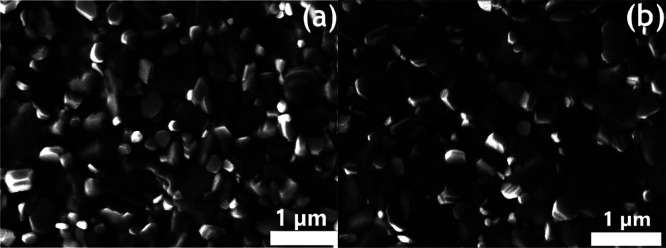
The improvement in PCE is mainly attributed to the significant increase in FF and secondly to a smaller increase in VOC. Figure 3b displays the dark J–V characteristics of the best-performing PSCs with and without the ZnO interlayer. The ZnO/SnO2-based cells delivered smaller reverse current showing better blocking behavior and lower defect densities.43,44 Composite ETLs, in fact, as in this case, reduce both pinholes and surface trap states which can be present at some of the interfaces of single ETLs34,37−39 in addition to the reduction of charge recombination at interfaces,45 suggested by higher shunt resistance compared to the cells with SnO2 only.38,46−48 SEM images of the perovskite films deposited on SnO2 and ZnO/SnO2 ETLs (Figure 4) reveal that also the bulk perovskite film improves when growing over the composite ETL. In fact, the average grain size of the perovskite film grown on ITO/ZnO/SnO2 (Figure 4b) was 300–350 nm, larger than the ∼220 nm size for films grown on ITO/SnO2 (Figure 4a). This difference contributes to the improvement in FF and VOC, as well as in the hysteresis behavior.49−52
Figure 4.
Top-view SEM images of perovskite films deposited on PET/ITO/SnO2 (a) and PET/ITO/ZnO/SnO2 (b).
3.1.3. Stability of Flexible Cells with Different ETLs
We performed light-soaking stability tests on the cells based on SnO2-NP single ETL and with ZnO/SnO2-NP bilayer ETL. Unencapsulated cells were illuminated with a solar simulator at one sun equivalent irradiation from white LEDs over a period of 2 h while tracking their maximum power point and measured every 30 min under ambient conditions, that is, temperature (25 °C) and relative humidity (RH) (30–60% range), that is, according to the ISOS-L-1 stability protocol.53Figure 5 shows the light-soaking effect on the PCE of our devices. The cells with SnO2 only were found to be more stable than cells with the ZnO/SnO2 ETLs.
Figure 5.
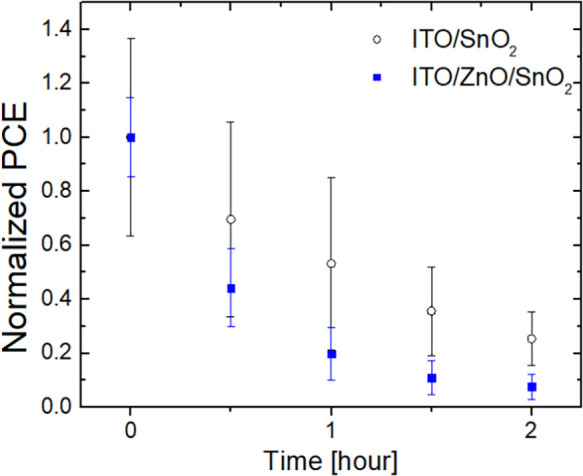
Light-soaking stability measurements at one sun illumination, under ambient temperature and RH in the range of 30–60%, over time of FPSCs with either SnO2 or ZnO/SnO2 ETLs.
Although the PCE improved for fresh cells compared to the reference devices when depositing ZnO under SnO2, the latter did not completely avoid interaction with the underlying ZnO and thus degradation of the perovskite films.21,22 This is not surprising since the SnO2-NP film is made of individual NPs and so a completely compact film that avoids all contact between ZnO and the perovskite film is unattainable for layers that are as thin as these (i.e., <80 nm).
SEM images (Figure 6) show that the surface of ZnO/SnO2 was rougher than that of the SnO2-NPs, which can be attributed to the granular NPs of the ZnO layer formed after annealing.54 This may also explain the different morphologies of the perovskite layers growing over the two types of ETL. Notably, a large concentration of small holes/craters can be seen in the ZnO/SnO2 SEM. These are likely areas where the perovskite comes into contact with the underlying ZnO. EDX analysis, shown in Figure 6, reveals that the surface of the ZnO/SnO2 bilayer consists of C, In, Sn, O, ZnO, and Si at 9.22, 7.59, 1.03, 71.29, 1.60, and 9.27 at. %, respectively, confirming that the SnO2 overlayer did not completely avoid direct interaction of the perovskite films with the underlying ZnO explaining the poorer stability of the cell with this type of ETL.
Figure 6.
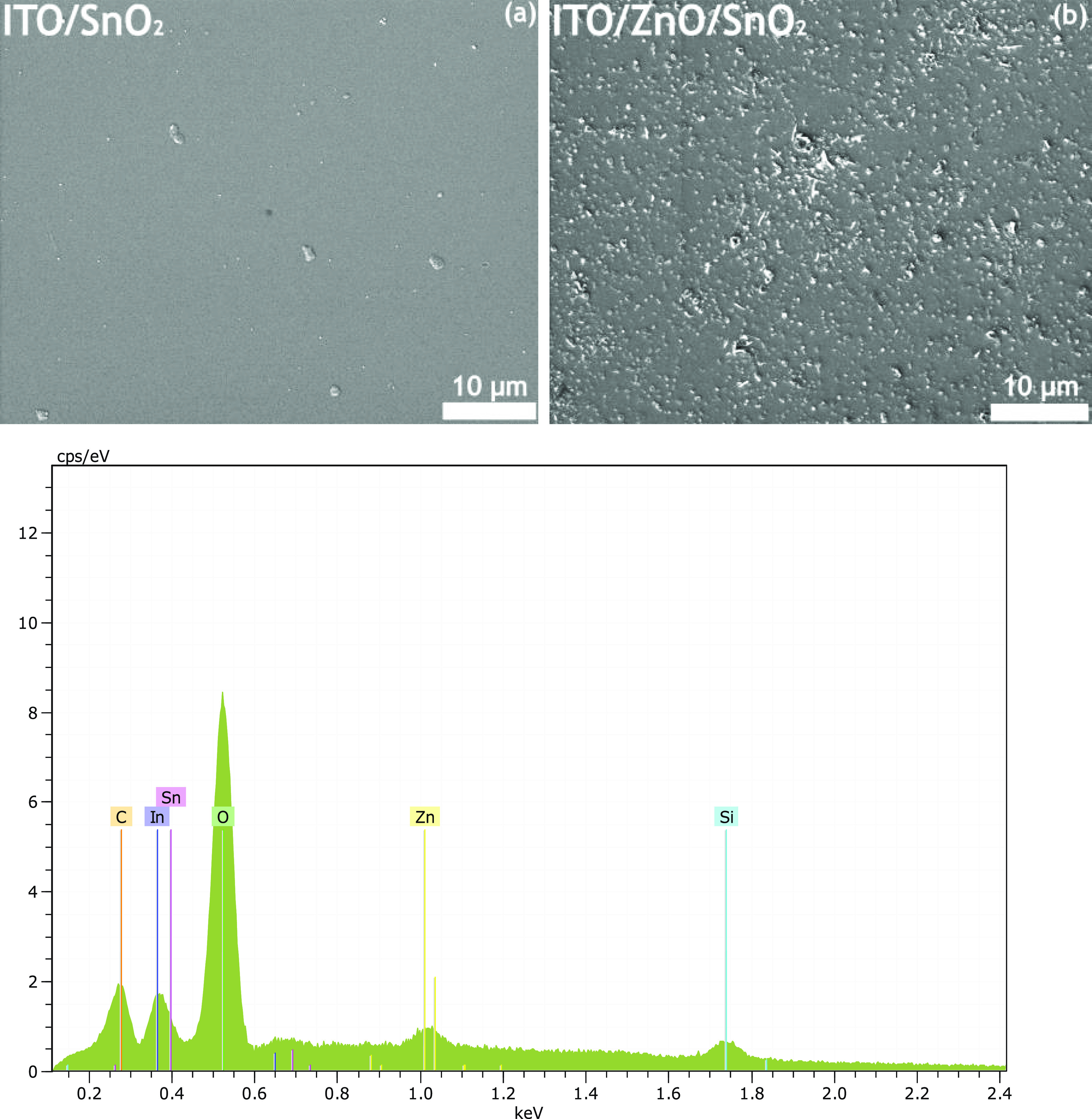
Top-view SEM images of (a) PET/ITO/SnO2, (b) PET/ITO/ZnO/SnO2 and EDX analysis of the PET/ITO/ZnO/SnO2 multilayer.
We also performed light-soaking stability measurements on the batches with SnO2/MgO- and SnO2/Al2O3-based cells. As shown in Figures S2 and S3, cells with SnO2-NP ETLs display better stability compared to those with double-layer ETLs, that is, SnO2/MgO and SnO2/Al2O3. This is different to the previously reported case on glass substrates, where the double-layer strategy did lead to better stability with respect to the SnO2 single layer only.37,46 It is worth noting that the double- and single-layer ETLs developed on glass substrates in refs (37) and (38) were made with SnO2-LP, not with NP.
Regarding mechanical stability under bending, this is limited not by the perovskite or transport layers but by the flexibility of the ITO which has a safe bending radius of 7 mm, as shown in previous studies.4,55,56 New transparent electrodes would need to be designed for going down to very low curvatures.56
3.1.4. SnO2-NP as the ETL of Choice for FPSCs
Our study shows that materials and recipes for PSCs on flexible substrates must be specifically developed and optimized for this particular substrate rather than just transferring them from glass-based devices since performance behavior will not match. Thus, if one wants to make highly efficient champion cells on flexible PET/ITO substrates, one could choose the ZnO/SnO2 ETL. However, considering stability together with more simple fabrication, then the better choice for ETL becomes that of SnO2-NP only. This NP-based SnO2-NP led to much more efficient and reproducible solar cells compared to the liquid precursor (SnO2-LP) alternative.
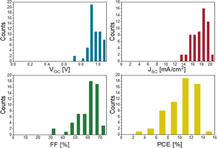
Figure 7 illustrates the statistical distribution of PV parameters measured for all 59 FPSCs that incorporated the SnO2-NP single ETL (from eight different batches fabricated over the course of 6 months of the study). The PCE distribution is mainly influenced by JSC and FF distributions. Of the 59 cells, 51 devices give a high VOC in the range from 0.9 to 1.1 V. The FF distribution is mostly found in the 60–70% range (60% of all cells). 5% of the cells reached an FF above 70%. Out of 59 cells, 19 had an efficiency of 10% or higher, 17 had an efficiency of 12% or higher, and the best cell with SnO2-NP single ETL reached a PCE of 14.1%.
Figure 7.
Statistical distribution of open-circuit voltage (VOC), current density (JSC), FF, and PCE of 59 flexible solar cells with PET/ITO/SnO2-NP/perovskite/spiro-OMeTAD/Au architecture from eight different batches fabricated over 6 months.
Further improvements in the future may be achieved by various treatments that can improve charge extraction or diminish the density of the trap state in the perovskite layer and at the perovskite/ETL interface.57,58 A strategy that could help improve the stability of the ZnO/SnO2 cells could be that of increasing the thickness of the SnO2 layer, as reported in the case of Al2O3 layers over ZnO with an increasing thicknesses of Al2O3 films.22 Nevertheless, SnO2-NP films represent an advantageous and easy-to-manufacture ETL specifically for FPSCs combining good performance, efficiency, and ease of fabrication. Furthermore, a planar device with SnO2-only ETL means there is only one layer to be deposited, decreasing the production time and cost.55,59,60
3.2. Understanding What Makes a Good ETL for FPSCs in Comparison with Those on Glass
In order to study performance differences when shifting from glass to flexible substrates, keeping the same architectures, we carried out a new set of eight types of devices on glass and flexible substrates: that is, SnO2, SnO2/MgO, ZnO/SnO2, and SnO2/Al2O3.
3.2.1. PV Performance of PSCs on Flexible PET versus Glass
The average PV parameters of all flexible and glass solar cells as a whole, as well as series resistance (RS), shunt resistance (RSH), forward and reverse currents under dark conditions (Ion and Ioff, respectively), and contact angles are summarized in Table 2 (see Table S2 for a breakdown for each type of ETL). As reported in the third column of Table 2, PCEs of glass cells were larger on average by 29% compared to cells fabricated on PET, with all PV parameters being boosted, especially JSC (+15%), then FF (+7%), and VOC (+6%).
Table 2. Average PV Parameters, Series Resistance RS, Shunt Resistance RSH, Forward Current Ion, Reverse Current Ioff, Contact Angles, and Relative Variation of All Parameters between PSCs Fabricated on Glass Versus Those on PETa.
| VOC (V) | JSC (mA/cm2) | FF (%) | PCE (%) | RS (Ω) | RSH (Ω) | Ion (mA) | Ioff (mA) | contact angle (°) | |
|---|---|---|---|---|---|---|---|---|---|
| PET cells | 0.96 ± 0.06 [1.04] | 15.7 ± 2.9 [17.1] | 51.9 ± 3.2 [66.07] | 7.9 ± 1.8 [11.75] | 319 ± 33 [448] | 6534 ± 3087.8 [8960] | 0.044 ± 0.02 [0.09 | 2.6 × 10⁻³ ± 1.7 × 10⁻³ [1.3 × 10⁻³] | 71.5 ± 8.7 |
| glass cells | 1.02 ± 0.05 [1.02] | 18.1 ± 3.0 [18.72] | 55.5 ± 3.4 [66.0] | 10.2 ± 1.9 [12.6] | 286 ± 43 [302] | 11 405 ± 2172 [20 800] | 0.047 ± 0.049 [0.131] | 6.32 × 10⁻⁴ ± 2.34 × 10⁻⁴ [4.97 × 10⁻⁴] | 53.5 ± 4.7 |
| relative variation between glass and PET cells | +6.3% [+1.9%] | +15.6% [+9.5%] | +6.9% [+0.12%] | +29.4% [+7.3%] | –10.4% [−32.6%] | +74.6% [+132%] | +6.8% [+45.6%] | –75.7% [−62%] | –25.2% |
In brackets, we report the values for the best cells.
3.2.2. How Shunt Resistances and Recombination Currents Underlie Performance Differences between Solar Cells
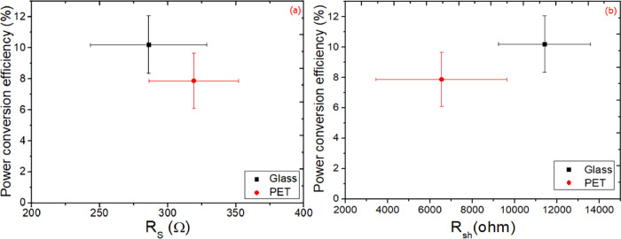
Figure 8 reports RS and RSH of all PET cells compared to those of all glass cells. It can be noticed that there is a decrease of around 10% in RS for the latter. This is due to ITO being more conductive (Rsheet was 8 and 15 Ω/sq for glass and PET-based substrates, respectively) which does not however make a significant difference at the very small cell level but would rather at the module level with wide ITO strips,58,61 as well as glass cells possessing better layers/interfaces. Instead, RSH doubles for glass-based devices versus PET, with the PCE increasing by 29% in relative terms, as a result mainly of higher JSC and FF, as illustrated in Figure S5.
Figure 8.
Dependence of average PCEs on series resistance (RS) (a) and shunt resistance (RSH) (b) of all flexible and rigid PSCs.
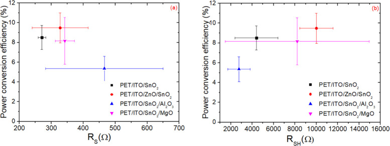
If we analyze the PET devices only (see Figure 9), the influence of the ETL on RSH is indeed huge. RSH was found to vary from roughly 2 × 10³ Ω for the cells with SnO2/Al2O3 bilayers to over 10 × 103 Ω for the cells with ZnO/SnO2 bilayers. We found that when RSH increased by a factor of ∼3, the average PCE of flexible cells almost doubled (from 5 to 9.5% in this batch of flexible cells studied). A good ETL needs to limit recombination losses, more so than improving RS. The variation of the latter is smaller but still significant in relative terms, that is, roughly a factor of 2, and can be mainly attributed to higher electron mobility, improved interface, improved perovskite morphology, and well-matched energy levels of ETL, which facilitate charge extraction from the perovskite to the electrodes.62−65 Lower shunt resistances, instead, generally arise from pinholes in the ETL as well as poor hole blocking behavior and interfacial defects, which produce recombination losses.65−67
Figure 9.
Dependence of average PCE on series resistance (RS) (a) and shunt resistance (RSH) (b) over the FPSCs with four different ETLs.
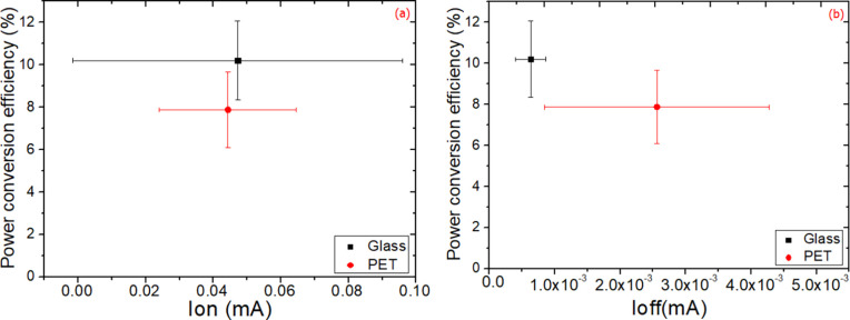
To delve deeper in the differences, Figure 10 shows that devices fabricated on glass have slightly higher on-dark currents, Ion, as well as significantly lower currents, Ioff. The former have a smaller impact on cell performance compared to the latter. In fact, the reverse bias current is 76% lower in relative terms on average for the glass devices, indicating considerably better blocking behavior, confirming the findings on shunt resistance. When the dark current is 76% lower, a relative 29% increase in PCE of glass devices was obtained. This leads to an improvement mainly in JSC and FF, as shown in Figure S6b,c. The lower reverse dark currents in glass devices compared to the ones on PET is a result of better blocking behavior and lower recombination currents at the electrode/ETL/perovskite interfaces.43,68 Whereas a breakdown of performance versus resistances on the different devices on PET confirms semiquantitatively the importance and the effect of these resistances (Figure 9), it was not possible to find a quantitative trend in Ion and Ioff due to the inherent large variation between devices for these parameters on PET (see Figure S7).
Figure 10.
Average PCEs of all flexible and rigid devices as a function of forward (Ion) (a) and reverse (Ioff) (b) currents measured in the dark extracted at 1 and −1 V, respectively.
3.2.3. Influence of Wetting and Contact Angle on Final Solar Cell Performance
In order to ascertain the origin of the better quality of the ETLs and the resulting better RS, RSH, Ioff, and PCE on glass substrates compared to those on PET, we performed contact angle measurements69 on the different ETLs on the different substrates (Figure 11) since it is the ITO/ETL/perovskite interface which determines to a great extent the series resistance and blocking behavior in the cells. The contact angle of the SnO2 layers increased from 49 to 77° when measured on glass and flexible substrates/ETLs, respectively (Figure 12). Better wetting at the interface ensures the formation of a perovskite film that is free of pinholes that would form shunt paths by inducing direct contact between the HTL and the ETL and reduce open-circuit voltage and FF. ETLs with better wetting properties can provide more complete coverage of the film with better crystallinity by assisting the nucleation of the perovskite and passivating crystal grain boundaries.58,70 The resulting higher-quality films translate in better PV performance, thus largely explaining the difference between PSCs on glass and flexible substrates.6,69,71Figure 12, in fact, permits us to highlight a more general trend: lower contact angles and better wetting of the inks over the electrode/ETL surface are conducive to delivering higher-quality transport layers, as well as interfaces with the perovskite, which in turn lead to better performance.6,58,72,73
Figure 11.
Water contact angle measurements over the different ETLs on glass (above) and PET (below) substrates.
Figure 12.
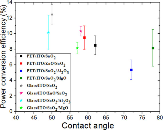
PCEs as a function of contact angles for both flexible and rigid PSCs fabricated with different ETLs.
4. Conclusions
We fabricated FPSCs using 12 different kinds of ETLs. Among all the ETLs, the cells with ZnO/SnO2 delivered a highest PCE of 14.8% at one sun illumination. The average PCE of ZnO/SnO2-based flexible PSCs was 39% higher, in relative terms, compared to SnO2-based cells fabricated in the same batch. With regard to the stability, the cells with SnO2-NP-only ETL were found to be more stable than cells with ZnO/SnO2 double ETL and generally more stable than all the double ETL-based devices investigated in this work. Thus, the most suitable of all 12 ETLs studied here was that consisting of SnO2 NPs. FPSCs with SnO2-NP delivered a PCE which was on average 250% higher than that of the same cells fabricated with SnO2 made with a liquid precursor.
Our study to understand the characteristics of what makes a good ETL on PET revealed that a good ETL should ensure high mobility, provide high shunt resistance, and reduce recombination currents. The main differences between glass and PET devices that give a performance advantage on glass (+29% in PCE in relative terms) are mainly found in shunt resistances and recombination currents. Moreover, we found that the wetting behavior of each ETL and the final performance of the device tended to be related for all ETLs and substrate types. Cell efficiency increases with a low contact angle, which is 25% lower for glass devices compared to flexible devices.
We can conclude that in order to obtain high-performing solar cells on PET/ITO substrates, it is necessary to focus and enhance more the blocking behavior of the ETL (rather than its transport properties). Furthermore, it is important to improve the wetting properties of the conductive substrate and ETL systems since achieving high-quality layers and interfaces was found to be related to better wetting of inks. These findings will be helpful for those laboratories migrating from glass devices to flexible ones, as well as those wanting to develop high-quality foundational ETLs over which device fabrication on plastic substrates starts.
Acknowledgments
This project has received funding from the Italian Ministry of University and Research (MIUR) through the PRIN2017 BOOSTER (project no. 2017YXX8AZ) grant from Lazio Region through ISIS@MACH (IR approved by Giunta Regionale no. G10795, 7 August 2019 published by BURL no. 69 27 August 2019) and the European Union’s Horizon 2020 research and innovation programme under grant agreement no 763989 APOLO. This publication reflects only the authors’ views and the funding agencies are not liable for any use that may be made of the information contained therein.
Supporting Information Available
The Supporting Information is available free of charge at https://pubs.acs.org/doi/10.1021/acsaem.1c03311.
PCE statistics, light stability, best PV parameters, average PV parameters, dependence of PV parameters on series resistance, shunt resistance, and reverse current (PDF)
The authors declare no competing financial interest.
Supplementary Material
References
- Jeon N. J.; Na H.; Jung E. H.; Yang T.-Y.; Lee Y. G.; Kim G.; Shin H.-W.; Il Seok S.; Lee J.; Seo J. A Fluorene-Terminated Hole-Transporting Material for Highly Efficient and Stable Perovskite Solar Cells. Nat. Energy 2018, 3, 682–689. 10.1038/s41560-018-0200-6. [DOI] [Google Scholar]
- Zarabinia N.; Lucarelli G.; Rasuli R.; De Rossi F.; Taheri B.; Javanbakht H.; Brunetti F.; Brown T. M. Simple and Effective Deposition Method for Solar Cell Perovskite Films Using a Sheet of Paper. iScience 2022, 25, 103712. 10.1016/j.isci.2021.103712. [DOI] [PMC free article] [PubMed] [Google Scholar]
- Di Giacomo F.; Fakharuddin A.; Jose R.; Brown T. M. Progress, Challenges and Perspectives in Flexible Perovskite Solar Cells. Energy Environ. Sci. 2016, 9, 3007–3035. 10.1039/c6ee01137c. [DOI] [Google Scholar]
- Di Giacomo F.; Zardetto V.; Lucarelli G.; Cinà L.; Di Carlo A.; Creatore M.; Brown T. M. Mesoporous Perovskite Solar Cells and the Role of Nanoscale Compact Layers for Remarkable All-Round High Efficiency under Both Indoor and Outdoor Illumination. Nano Energy 2016, 30, 460–469. 10.1016/j.nanoen.2016.10.030. [DOI] [Google Scholar]
- Lucarelli G.; Di Giacomo F.; Zardetto V.; Creatore M.; Brown T. M. Efficient Light Harvesting from Flexible Perovskite Solar Cells under Indoor White Light-Emitting Diode Illumination. Nano Res. 2017, 10, 2130–2145. 10.1007/s12274-016-1402-5. [DOI] [Google Scholar]
- Castro-Hermosa S.; Lucarelli G.; Top M.; Fahland M.; Fahlteich J.; Brown T. M. Perovskite Photovoltaics on Roll-To-Roll Coated Ultra-Thin Glass as Flexible High-Efficiency Indoor Power Generators. Cell Rep. Phys. Sci. 2020, 1, 100045. 10.1016/j.xcrp.2020.100045. [DOI] [Google Scholar]
- Dagar J.; Castro-Hermosa S.; Gasbarri M.; Palma A. L.; Cina L.; Matteocci F.; Calabrò E.; Di Carlo A.; Brown T. M. Efficient Fully Laser-Patterned Flexible Perovskite Modules and Solar Cells Based on Low-Temperature Solution-Processed SnO2/Mesoporous-TiO2 Electron Transport Layers. Nano Res. 2018, 11, 2669–2681. 10.1007/s12274-017-1896-5. [DOI] [Google Scholar]
- Rajagopal A.; Yao K.; Jen A. K. Y. Toward Perovskite Solar Cell Commercialization: A Perspective and Research Roadmap Based on Interfacial Engineering. Adv. Mater. 2018, 30, 1800455. 10.1002/adma.201800455. [DOI] [PubMed] [Google Scholar]
- Guo X.; Zhang B.; Lin Z.; Ma J.; Su J.; Zhu W.; Zhang C.; Zhang J.; Chang J.; Hao Y. Interface Engineering of TiO2/Perovskite Interface via Fullerene Derivatives for High Performance Planar Perovskite Solar Cells. Org. Electron. 2018, 62, 459–467. 10.1016/j.orgel.2018.08.039. [DOI] [Google Scholar]
- Zhao W.; Li H.; Li D.; Liu Z.; Wang D.; Liu S.; Frank Comprehensive Investigation of Sputtered and Spin-Coated Zinc Oxide Electron Transport Layers for Highly Efficient and Stable Planar Perovskite Solar Cells. J. Power Sources 2019, 427, 223–230. 10.1016/j.jpowsour.2019.04.088. [DOI] [Google Scholar]
- Azmi R.; Hadmojo W. T.; Sinaga S.; Lee C.-L.; Yoon S. C.; Jung I. H.; Jang S.-Y. High-Efficiency Low-Temperature ZnO Based Perovskite Solar Cells Based on Highly Polar, Nonwetting Self-Assembled Molecular Layers. Adv. Energy Mater. 2018, 8, 1701683. 10.1002/aenm.201701683. [DOI] [Google Scholar]
- Yang G.; Chen C.; Yao F.; Chen Z.; Zhang Q.; Zheng X.; Ma J.; Lei H.; Qin P.; Xiong L.; Ke W.; Li G.; Yan Y.; Fang G. Effective Carrier-Concentration Tuning of SnO2 Quantum Dot Electron-Selective Layers for High-Performance Planar Perovskite Solar Cells. Adv. Mater. 2018, 30, 1706023. 10.1002/adma.201706023. [DOI] [PubMed] [Google Scholar]
- Calabrò E.; Matteocci F.; Palma A. L.; Vesce L.; Taheri B.; Carlini L.; Pis I.; Nappini S.; Dagar J.; Battocchio C.; Brown T. M.; Di Carlo A. Low Temperature, Solution-Processed Perovskite Solar Cells and Modules with an Aperture Area Efficiency of 11%. Sol. Energy Mater. Sol. Cells 2018, 185, 136–144. 10.1016/j.solmat.2018.05.001. [DOI] [Google Scholar]
- Zardetto V.; Brown T. M.; Reale A.; Di Carlo A. Substrates for Flexible Electronics: A Practical Investigation on the Electrical, Film Flexibility, Optical, Temperature, and Solvent Resistance Properties. J. Polym. Sci., Part B: Polym. Phys. 2011, 49, 638–648. 10.1002/polb.22227. [DOI] [Google Scholar]
- Wang F.; Zhang Y.; Yang M.; Du J.; Yang L.; Fan L.; Sui Y.; Liu X.; Yang J. Achieving Efficient Flexible Perovskite Solar Cells with Room-Temperature Processed Tungsten Oxide Electron Transport Layer. J. Power Sources 2019, 440, 227157. 10.1016/j.jpowsour.2019.227157. [DOI] [Google Scholar]
- Chu W.; Li X.; Li S.; Hou J.; Jiang Q.; Yang J. High-Performance Flexible Perovskite Solar Cells with a Metal Sulfide Electron Transport Layer of SnS2 by Room-Temperature Vacuum Deposition. ACS Appl. Energy Mater. 2019, 2, 382–388. 10.1021/acsaem.8b01405. [DOI] [Google Scholar]
- Liu X.; Chueh C.-C.; Zhu Z.; Jo S. B.; Sun Y.; Jen A. K.-Y. Highly Crystalline Zn2SnO4 Nanoparticles as Efficient Electron-Transporting Layers toward Stable Inverted and Flexible Conventional Perovskite Solar Cells. J. Mater. Chem. A 2016, 4, 15294–15301. 10.1039/c6ta05745d. [DOI] [Google Scholar]
- Shin S. S.; Yang W. S.; Noh J. H.; Suk J. H.; Jeon N. J.; Park J. H.; Kim J. S.; Seong W. M.; Seok S. I. High-Performance Flexible Perovskite Solar Cells Exploiting Zn2SnO4 Prepared in Solution below 100 °C. Nat. Commun. 2015, 6, 7410. 10.1038/ncomms8410. [DOI] [PMC free article] [PubMed] [Google Scholar]
- Shin S. S.; Yang W. S.; Yeom E. J.; Lee S. J.; Jeon N. J.; Joo Y.-C.; Park I. J.; Noh J. H.; Seok S. I. Tailoring of Electron-Collecting Oxide Nanoparticulate Layer for Flexible Perovskite Solar Cells. J. Phys. Chem. Lett. 2016, 7, 1845–1851. 10.1021/acs.jpclett.6b00295. [DOI] [PubMed] [Google Scholar]
- Liu D.; Kelly T. L. Perovskite Solar Cells with a Planar Heterojunction Structure Prepared Using Room-Temperature Solution Processing Techniques. Nat. Photonics 2014, 8, 133–138. 10.1038/nphoton.2013.342. [DOI] [Google Scholar]
- Cheng Y.; Yang Q.-D.; Xiao J.; Xue Q.; Li H.-W.; Guan Z.; Yip H.-L.; Tsang S.-W. Decomposition of Organometal Halide Perovskite Films on Zinc Oxide Nanoparticles. ACS Appl. Mater. Interfaces 2015, 7, 19986–19993. 10.1021/acsami.5b04695. [DOI] [PubMed] [Google Scholar]
- Si H.; Liao Q.; Zhang Z.; Li Y.; Yang X.; Zhang G.; Kang Z.; Zhang Y. An Innovative Design of Perovskite Solar Cells with Al2O3 Inserting at ZnO/Perovskite Interface for Improving the Performance and Stability. Nano Energy 2016, 22, 223–231. 10.1016/j.nanoen.2016.02.025. [DOI] [Google Scholar]
- Taheri B.; De Rossi F.; Lucarelli G.; Castriotta L. A.; Di Carlo A.; Brown T. M.; Brunetti F. Laser-Scribing Optimization for Sprayed SnO2 -Based Perovskite Solar Modules on Flexible Plastic Substrates. ACS Appl. Energy Mater. 2021, 4, 4507–4518. 10.1021/acsaem.1c00140. [DOI] [PMC free article] [PubMed] [Google Scholar]
- Castro-Hermosa S.; Dagar J.; Marsella A.; Brown T. M. Perovskite Solar Cells on Paper and the Role of Substrates and Electrodes on Performance. IEEE Electron Device Lett. 2017, 38, 1278–1281. 10.1109/led.2017.2735178. [DOI] [Google Scholar]
- Zhu Z.; Bai Y.; Liu X.; Chueh C.-C.; Yang S.; Jen A. K.-Y. Enhanced Efficiency and Stability of Inverted Perovskite Solar Cells Using Highly Crystalline SnO2 Nanocrystals as the Robust Electron-Transporting Layer. Adv. Mater. 2016, 28, 6478–6484. 10.1002/adma.201600619. [DOI] [PubMed] [Google Scholar]
- Jiang Q.; Zhang X.; You J. SnO2 : A Wonderful Electron Transport Layer for Perovskite Solar Cells. Small 2018, 14, 1801154. 10.1002/smll.201801154. [DOI] [PubMed] [Google Scholar]
- Taheri B.; Calabrò E.; Matteocci F.; Di Girolamo D.; Cardone G.; Liscio A.; Di Carlo A.; Brunetti F. Automated Scalable Spray Coating of SnO2 for the Fabrication of Low-Temperature Perovskite Solar Cells and Modules. Energy Technol. 2020, 8, 1901284. 10.1002/ente.201901284. [DOI] [Google Scholar]
- Huang X.; Du J.; Guo X.; Lin Z.; Ma J.; Su J.; Feng L.; Zhang C.; Zhang J.; Chang J.; Hao Y. Polyelectrolyte-Doped SnO2 as a Tunable Electron Transport Layer for High-Efficiency and Stable Perovskite Solar Cells. Sol. RRL 2020, 4, 1900336. 10.1002/solr.201900336. [DOI] [Google Scholar]
- Wang C.; Guan L.; Zhao D.; Yu Y.; Grice C. R.; Song Z.; Awni R. A.; Chen J.; Wang J.; Zhao X.; Yan Y. Water Vapor Treatment of Low-Temperature Deposited SnO2 Electron Selective Layers for Efficient Flexible Perovskite Solar Cells. ACS Energy Lett. 2017, 2, 2118–2124. 10.1021/acsenergylett.7b00644. [DOI] [Google Scholar]
- Bu T.; Li J.; Zheng F.; Chen W.; Wen X.; Ku Z.; Peng Y.; Zhong J.; Cheng Y.-B.; Huang F. Universal Passivation Strategy to Slot-Die Printed SnO2 for Hysteresis-Free Efficient Flexible Perovskite Solar Module. Nat. Commun. 2018, 9, 4609. 10.1038/s41467-018-07099-9. [DOI] [PMC free article] [PubMed] [Google Scholar]
- Wu Q.; Zhou W.; Liu Q.; Zhou P.; Chen T.; Lu Y.; Qiao Q.; Yang S. Solution-Processable Ionic Liquid as an Independent or Modifying Electron Transport Layer for High-Efficiency Perovskite Solar Cells. ACS Appl. Mater. Interfaces 2016, 8, 34464–34473. 10.1021/acsami.6b12683. [DOI] [PubMed] [Google Scholar]
- Yang D.; Yang R.; Ren X.; Zhu X.; Yang Z.; Li C.; Liu S. F. Hysteresis-Suppressed High-Efficiency Flexible Perovskite Solar Cells Using Solid-State Ionic-Liquids for Effective Electron Transport. Adv. Mater. 2016, 28, 5206–5213. 10.1002/adma.201600446. [DOI] [PubMed] [Google Scholar]
- Thambidurai M.; Shini F.; Harikesh P. C.; Mathews N.; Dang C. Highly Stable and Efficient Planar Perovskite Solar Cells Using Ternary Metal Oxide Electron Transport Layers. J. Power Sources 2020, 448, 227362. 10.1016/j.jpowsour.2019.227362. [DOI] [Google Scholar]
- Chen R.; Cao J.; Duan Y.; Hui Y.; Chuong T. T.; Ou D.; Han F.; Cheng F.; Huang X.; Wu B.; Zheng N. High-Efficiency, Hysteresis-Less, UV-Stable Perovskite Solar Cells with Cascade ZnO–ZnS Electron Transport Layer. J. Am. Chem. Soc. 2019, 141, 541–547. 10.1021/jacs.8b11001. [DOI] [PubMed] [Google Scholar]
- Chung J.; Shin S. S.; Hwang K.; Kim G.; Kim K. W.; Lee D. S.; Kim W.; Ma B. S.; Kim Y.-K.; Kim T.-S.; Seo J. Record-Efficiency Flexible Perovskite Solar Cell and Module Enabled by a Porous-Planar Structure as an Electron Transport Layer. Energy Environ. Sci. 2020, 13, 4854–4861. 10.1039/d0ee02164d. [DOI] [Google Scholar]
- He R.; Nie S.; Huang X.; Wu Y.; Chen R.; Yin J.; Wu B.; Li J.; Zheng N. Scalable Preparation of High-Performance ZnO-SnO 2 Cascaded Electron Transport Layer for Efficient Perovskite Solar Modules. Sol. RRL 2021, 6, 2100639. 10.1002/solr.202100639. [DOI] [Google Scholar]
- Dagar J.; Castro-Hermosa S.; Lucarelli G.; Cacialli F.; Brown T. M. Highly efficient perovskite solar cells for light harvesting under indoor illumination via solution processed SnO2/MgO composite electron transport layers. Nano Energy 2018, 49, 290–299. 10.1016/j.nanoen.2018.04.027. [DOI] [Google Scholar]
- Dagar J.; Castro-Hermosa S.; Lucarelli G.; Zampetti A.; Cacialli F.; Brown T. M. Low-Temperature Solution-Processed Thin SnO 2/Al2O3 Double Electron Transport Layers Toward 20% Efficient Perovskite Solar Cells. IEEE J. Photovolt. 2019, 9, 1309–1315. 10.1109/jphotov.2019.2928466. [DOI] [Google Scholar]
- Ierides I.; Squires I.; Lucarelli G.; Brown T. M.; Cacialli F. Inverted Organic Photovoltaics with a Solution-Processed ZnO/MgO Electron Transport Bilayer. J. Mater. Chem. C 2021, 9, 3901–3910. 10.1039/d0tc04955g. [DOI] [Google Scholar]
- Wang D.; Wu C.; Luo W.; Guo X.; Qu B.; Xiao L.; Chen Z. ZnO/SnO2 Double Electron Transport Layer Guides Improved Open Circuit Voltage for Highly Efficient CH 3 NH 3 PbI3 -Based Planar Perovskite Solar Cells. ACS Appl. Energy Mater. 2018, 1, 2215–2221. 10.1021/acsaem.8b00293. [DOI] [Google Scholar]
- Wang D.; Chen S.-C.; Zheng Q. Poly(Vinylpyrrolidone)-Doped SnO2 as an Electron Transport Layer for Perovskite Solar Cells with Improved Performance. J. Mater. Chem. C 2019, 7, 12204–12210. 10.1039/c9tc04269e. [DOI] [Google Scholar]
- Yang D.; Zhou X.; Yang R.; Yang Z.; Yu W.; Wang X.; Li C.; Liu S.; Chang R. P. H.; Chang R. P. H. Surface Optimization to Eliminate Hysteresis for Record Efficiency Planar Perovskite Solar Cells. Energy Environ. Sci. 2016, 9, 3071–3078. 10.1039/c6ee02139e. [DOI] [Google Scholar]
- Cowan S. R.; Leong W. L.; Banerji N.; Dennler G.; Heeger A. J. Identifying a Threshold Impurity Level for Organic Solar Cells: Enhanced First-Order Recombination Via Well-Defined PC84BM Traps in Organic Bulk Heterojunction Solar Cells. Adv. Funct. Mater. 2011, 21, 3083–3092. 10.1002/adfm.201100514. [DOI] [Google Scholar]
- Zardetto V.; Di Giacomo F.; Lucarelli G.; Kessels W. M. M.; Brown T. M.; Creatore M. Plasma-assisted atomic layer deposition of TiO2 compact layers for flexible mesostructured perovskite solar cells. Sol. Energy 2017, 150, 447–453. 10.1016/j.solener.2017.04.028. [DOI] [Google Scholar]
- Bartesaghi D.; Pérez I. d. C.; Kniepert J.; Roland S.; Turbiez M.; Neher D.; Koster L. J. A. Competition between Recombination and Extraction of Free Charges Determines the Fill Factor of Organic Solar Cells. Nat. Commun. 2015, 6, 7083. 10.1038/ncomms8083. [DOI] [PMC free article] [PubMed] [Google Scholar]
- Zhao X.; Tao L.; Li H.; Huang W.; Sun P.; Liu J.; Liu S.; Sun Q.; Cui Z.; Sun L.; Shen Y.; Yang Y.; Wang M. Efficient Planar Perovskite Solar Cells with Improved Fill Factor via Interface Engineering with Graphene. Nano Lett. 2018, 18, 2442–2449. 10.1021/acs.nanolett.8b00025. [DOI] [PubMed] [Google Scholar]
- Lin L.; Yang Z.; Jiang E.; Wang Z.; Yan J.; Li N.; Wang Z.; Ai Y.; Shou C.; Yan B.; Zhu Y.; Sheng J.; Ye J. ZnO-Modified Anode for High-Performance SnO2-Based Planar Perovskite Solar Cells. ACS Appl. Energy Mater. 2019, 2, 7062–7069. 10.1021/acsaem.9b00845. [DOI] [Google Scholar]
- Wojciechowski K.; Stranks S. D.; Abate A.; Sadoughi G.; Sadhanala A.; Kopidakis N.; Rumbles G.; Li C.-Z.; Friend R. H.; Jen A. K.-Y.; Snaith H. J. Heterojunction Modification for Highly Efficient Organic–Inorganic Perovskite Solar Cells. ACS Nano 2014, 8, 12701–12709. 10.1021/nn505723h. [DOI] [PubMed] [Google Scholar]
- Ren X.; Yang Z.; Yang D.; Zhang X.; Cui D.; Liu Y.; Wei Q.; Fan H.; Liu S.; Frank Modulating Crystal Grain Size and Optoelectronic Properties of Perovskite Films for Solar Cells by Reaction Temperature. Nanoscale 2016, 8, 3816–3822. 10.1039/c5nr08935b. [DOI] [PubMed] [Google Scholar]
- Dong Q.; Yuan Y.; Shao Y.; Fang Y.; Wang Q.; Huang J. Abnormal Crystal Growth in CH3NH3PbI 3–x Cl x Using a Multi-Cycle Solution Coating Process. Energy Environ. Sci. 2015, 8, 2464–2470. 10.1039/c5ee01179e. [DOI] [Google Scholar]
- Bi C.; Wang Q.; Shao Y.; Yuan Y.; Xiao Z.; Huang J. Non-Wetting Surface-Driven High-Aspect-Ratio Crystalline Grain Growth for Efficient Hybrid Perovskite Solar Cells. Nat. Commun. 2015, 6, 7747. 10.1038/ncomms8747. [DOI] [PMC free article] [PubMed] [Google Scholar]
- Xiao Z.; Dong Q.; Bi C.; Shao Y.; Yuan Y.; Huang J. Solvent Annealing of Perovskite-Induced Crystal Growth for Photovoltaic-Device Efficiency Enhancement. Adv. Mater. 2014, 26, 6503–6509. 10.1002/adma.201401685. [DOI] [PubMed] [Google Scholar]
- Reese M. O.; Gevorgyan S. A.; Jørgensen M.; Bundgaard E.; Kurtz S. R.; Ginley D. S.; Olson D. C.; Lloyd M. T.; Morvillo P.; Katz E. A.; Elschner A.; Haillant O.; Currier T. R.; Shrotriya V.; Hermenau M.; Riede M.; Kirov R. K.; Trimmel G.; Rath T.; Inganäs O.; Zhang F.; Andersson M.; Tvingstedt K.; Lira-Cantu M.; Laird D.; McGuiness C.; Gowrisanker S.; Pannone M.; Xiao M.; Hauch J.; Steim R.; DeLongchamp D. M.; Rösch R.; Hoppe H.; Espinosa A.; Yaman-Uzunoglu G.; Bonekamp J.-B.; van Breemen A. J. J. M.; Girotto C.; Voroshazi E.; Krebs F. C. Consensus Stability Testing Protocols for Organic Photovoltaic Materials and Devices. Sol. Energy Mater. Sol. Cells 2011, 95, 1253–1267. 10.1016/j.solmat.2011.01.036. [DOI] [Google Scholar]
- Noh Y. W.; Jin I. S.; Kim K. S.; Park S. H.; Jung J. W. Reduced Energy Loss in SnO2/ZnO Bilayer Electron Transport Layer-Based Perovskite Solar Cells for Achieving High Efficiencies in Outdoor/Indoor Environments. J. Mater. Chem. A 2020, 8, 17163–17173. 10.1039/d0ta04721j. [DOI] [Google Scholar]
- Meng L.; You J.; Guo T.-F.; Yang Y. Recent Advances in the Inverted Planar Structure of Perovskite Solar Cells. Acc. Chem. Res. 2016, 49, 155–165. 10.1021/acs.accounts.5b00404. [DOI] [PubMed] [Google Scholar]
- Lucarelli G.; Brown T. M. Development of Highly Bendable Transparent Window Electrodes Based on MoOx, SnO2, and Au Dielectric/Metal/Dielectric Stacks: Application to Indium Tin Oxide (ITO)-Free Perovskite Solar Cells. Front. Mater. 2019, 6, 310. 10.3389/fmats.2019.00310. [DOI] [Google Scholar]
- Xiong L.; Guo Y.; Wen J.; Liu H.; Yang G.; Qin P.; Fang G. Review on the Application of SnO2 in Perovskite Solar Cells. Adv. Funct. Mater. 2018, 28, 1802757. 10.1002/adfm.201802757. [DOI] [Google Scholar]
- Yang D.; Yang R.; Wang K.; Wu C.; Zhu X.; Feng J.; Ren X.; Fang G.; Priya S.; Liu S. High Efficiency Planar-Type Perovskite Solar Cells with Negligible Hysteresis Using EDTA-Complexed SnO2. Nat. Commun. 2018, 9, 3239. 10.1038/s41467-018-05760-x. [DOI] [PMC free article] [PubMed] [Google Scholar]
- Pascoe A. R.; Yang M.; Kopidakis N.; Zhu K.; Reese M. O.; Rumbles G.; Fekete M.; Duffy N. W.; Cheng Y.-B. Planar versus Mesoscopic Perovskite Microstructures: The Influence of CH3NH3PbI3 Morphology on Charge Transport and Recombination Dynamics. Nano Energy 2016, 22, 439–452. 10.1016/j.nanoen.2016.02.031. [DOI] [Google Scholar]
- Yang W. S.; Noh J. H.; Jeon N. J.; Kim Y. C.; Ryu S.; Seo J.; Seok S. I. High-Performance Photovoltaic Perovskite Layers Fabricated through Intramolecular Exchange. Science 2015, 348, 1234–1237. 10.1126/science.aaa9272. [DOI] [PubMed] [Google Scholar]
- Galagan Y.; Coenen E. W. C.; Verhees W. J. H.; Andriessen R. Towards the Scaling up of Perovskite Solar Cells and Modules. J. Mater. Chem. A 2016, 4, 5700–5705. 10.1039/c6ta01134a. [DOI] [Google Scholar]
- Kim T.; Lim J.; Song S. Recent Progress and Challenges of Electron Transport Layers in Organic–Inorganic Perovskite Solar Cells. Energies 2020, 13, 5572. 10.3390/en13215572. [DOI] [Google Scholar]
- Wu M.-C.; Chan S.-H.; Jao M.-H.; Su W.-F. Enhanced Short-Circuit Current Density of Perovskite Solar Cells Using Zn-Doped TiO2 as Electron Transport Layer. Sol. Energy Mater. Sol. Cells 2016, 157, 447–453. 10.1016/j.solmat.2016.07.003. [DOI] [Google Scholar]
- Ju S.; Byun M.; Kim M.; Jun J.; Huh D.; Kim D. S.; Jo Y.; Lee H. Fabrication of Perovskite Solar Cell with High Short-Circuit Current Density (JSC) Using Moth-Eye Structure of SiOX. Nano Res. 2020, 13, 1156–1161. 10.1007/s12274-020-2763-3. [DOI] [Google Scholar]
- Lee J.; Baik S. Enhanced Crystallinity of CH3NH3PbI3 by the Pre-Coordination of PbI2 −DMSO Powders for Highly Reproducible and Efficient Planar Heterojunction Perovskite Solar Cells. RSC Adv. 2018, 8, 1005–1013. 10.1039/c7ra12304c. [DOI] [PMC free article] [PubMed] [Google Scholar]
- Giordano F.; Petrolati E.; Brown T. M.; Reale A.; Di Carlo A. Series-Connection Designs for Dye Solar Cell Modules. IEEE Trans. Electron Devices 2011, 58, 2759–2764. 10.1109/ted.2011.2158216. [DOI] [Google Scholar]
- Qiu W.; Merckx T.; Jaysankar M.; Masse de la Huerta C.; Rakocevic L.; Zhang W.; Paetzold U. W.; Gehlhaar R.; Froyen L.; Poortmans J.; Cheyns D.; Snaith H. J.; Heremans P. Pinhole-Free Perovskite Films for Efficient Solar Modules. Energy Environ. Sci. 2016, 9, 484–489. 10.1039/c5ee03703d. [DOI] [Google Scholar]
- Li Y.; Ding B.; Chu Q.-Q.; Yang G.-J.; Wang M.; Li C.-X.; Li C.-J. Ultra-High Open-Circuit Voltage of Perovskite Solar Cells Induced by Nucleation Thermodynamics on Rough Substrates. Sci. Rep. 2017, 7, 46141. 10.1038/srep46141. [DOI] [PMC free article] [PubMed] [Google Scholar]
- Singh R.; Sandhu S.; Lee J.-J. Elucidating the Effect of Shunt Losses on the Performance of Mesoporous Perovskite Solar Cells. Sol. Energy 2019, 193, 956–961. 10.1016/j.solener.2019.10.018. [DOI] [Google Scholar]
- Bi D.; Yi C.; Luo J.; Décoppet J.-D.; Zhang F.; Zakeeruddin S. M.; Li X.; Hagfeldt A.; Grätzel M. Polymer-Templated Nucleation and Crystal Growth of Perovskite Films for Solar Cells with Efficiency Greater than 21%. Nat. Energy 2016, 1, 16142. 10.1038/nenergy.2016.142. [DOI] [Google Scholar]
- Yang G.; Wang C.; Lei H.; Zheng X.; Qin P.; Xiong L.; Zhao X.; Yan Y.; Fang G. Interface Engineering in Planar Perovskite Solar Cells: Energy Level Alignment, Perovskite Morphology Control and High Performance Achievement. J. Mater. Chem. A 2017, 5, 1658–1666. 10.1039/c6ta08783c. [DOI] [Google Scholar]
- Cao J.-J.; Wang K.-L.; Dong C.; Li X.-M.; Yang W.-F.; Wang Z.-K. Bottom-Contact Passivation for High-Performance Perovskite Solar Cells Using TaCl5-Doped SnO2 as Electron-Transporting Layer. Org. Electron. 2021, 88, 105972. 10.1016/j.orgel.2020.105972. [DOI] [Google Scholar]
- Huang F.; Wei Y.; Gu L.; Guo Q.; Xu H.; Luo D.; Jin S.; Yang X.; Huang Y.; Wu J. Interface Engineering of Electron Transport Layer-Free Planar Perovskite Solar Cells with Efficiency Exceeding 15%. Energy Technol. 2017, 5, 1844–1851. 10.1002/ente.201700437. [DOI] [Google Scholar]
Associated Data
This section collects any data citations, data availability statements, or supplementary materials included in this article.


