Abstract
A propagation pattern for the moment representation of the regularized lattice Boltzmann method (LBM) in three dimensions is presented. Using effectively lossless compression, the simulation state is stored as a set of moments of the lattice Boltzmann distribution function, instead of the distribution function itself. An efficient cache-aware propagation pattern for this moment representation has the effect of substantially reducing both the storage and memory bandwidth required for LBM simulations. This paper extends recent work with the moment representation by expanding the performance analysis on central processing unit (CPU) architectures, considering how boundary conditions are implemented, and demonstrating the effectiveness of the moment representation on a graphics processing unit (GPU) architecture.
Keywords: Lattice Boltzmann methods, High performance computing, Fluid dynamics
1. INTRODUCTION
Managing data motion remains a key challenge to developing efficient, scalable algorithms for computational multiphysics. As floating point operations become increasingly inexpensive, reworking existing algorithms to reduce the required memory bandwidth becomes an important avenue to improving computational performance. For instance, the lattice Boltzmann method (LBM) has been widely applied within computational fluid dynamics and related domains (e.g., porous media [1], additive manufacturing [2], and supersonic flows [3]). However, LBM simulations are highly memory-bound on modern architectures [4]. In our previous work [5], we reformulated a regularized lattice Boltzmann method to store LBM simulation data in a compressed format based on moments. Combined with a cache-aware propagation pattern maximizing data reuse, this scheme substantially reduces the memory and data motion required for LBM. In this companion paper, we extend the performance analysis of the scheme, discuss integration with boundary conditions and complex geometries, and port the scheme for graphics processing unit (GPU) architectures.
One approach to reducing LBM’s storage and memory bandwidth requirements involves developing more efficient propagation patterns. There are two fundamental computational kernels, collision and streaming, in the LBM timestep. Baseline propagation patterns for LBM implement these kernels as separate routines. While separate routines enable individual optimizations of each kernel, the arrangement is not optimal with respect to overall data motion. To address this, collision and streaming are ‘fused’ into a single kernel to reduce the amount of data motion to and from memory [6], [7]. Subsequently, a series of LBM propagation patterns (AA, swap, shift, esoteric twist, etc.) have been developed that store a single copy of the distribution array [6], [8], [9], [10]. While originally designed to reduce storage requirements, some of these propagation patterns may also further reduce data motion by avoiding write allocates [11].
A second approach to reducing data motion and storage for LBM is to simplify the lattice Boltzmann method itself. Several such implementations store only the density and momentum variables, analogously to pressure and velocity in Navier-Stokes (e.g., [12], [13], [14]). This reduction is valid for the special case where the LBM relaxation time τ = 1. However, for larger Reynolds numbers, an extremely high resolution grid would be required to maintain a sufficiently small Mach number to ensure stability [14]. A more advanced version of this idea, introduced by Argentini et al., stores additional moments beyond density and momentum but is still limited to low Reynolds numbers [15]. Consequently, while effective at decreasing memory requirements, this approach is less well-suited for non-laminar flows.
Instead, regularization provides a more general approach to data reduction for the lattice Boltzmann method. Regularization is an integral component in the formulation of LBM schemes for finite Knudsen numbers [16] and microfluidic flows [17]. Regularization has also proven key to maintaining stability at high Reynolds numbers [18], [19]. The fundamental idea of this projection-based regularization process is to base the number of degrees of freedom on the moments of the physical system being approximated by LBM, rather than on the number of distribution components in the LBM lattice [20]. With fewer such moments than distribution components, it becomes possible to decrease the memory bandwidth and storage requirements. Moreover, this compression is effectively lossless because the moments are chosen so as to maintain the same order of approximation of the physical equation (e.g., Navier-Stokes) being solved with LBM [21].
In this paper, we extend our recent work in developing a moment-based propagation pattern of the regularized lattice Boltzmann method [5]. We take full advantage of the simplifications provided by regularized LBM and integrate them into a propagation pattern that reduces both in-memory storage and memory bandwidth requirements. Along with a more thorough explanation of the proposed algorithm, this extension paper makes three additional contributions:
First, we compare performance of our moment representation algorithm with two benchmark LBM implementations, measuring performance versus a roofline model for two central processing unit (CPU) architectures and for two LBM lattices. Additionally, we evaluate factors associated with the algorithm’s cache usage and performance.
Second, we discuss implementing LBM boundary conditions with the moment representation.
Third, we show how our moment representation algorithm can be adapted to GPUs and demonstrate improved performance for 2D simulations.
2. LATTICE BOLTZMANN METHODS
2.1. Single relaxation time LBM
LBM simulations evolve according to the lattice Boltzmann equation [22]. Formulated in terms of the LBM particle distribution function f and using the single relaxation time (BGK) collision operator, the equation may be written for each distribution component fi as
| (1) |
for the approximation of the Maxwell-Boltzmann equilibrium distribution, discrete velocities ci of the lattice, relaxation time τ, lattice site x, and timestep t. Equivalently, the right side of the equation 1 may be rewritten as
| (2) |
where the non-equilibrium distribution is computed as . It is conceptually convenient to separate the right and left sides of equation 2 into ‘collision’ and ‘streaming’ kernels, respectively:
| (3) |
| (4) |
This distinction is useful because collision is local to the lattice site and nonlinear, while streaming is non-local but linear. Hydrodynamic variables are computed as moments of distribution f with respect to Hermite polynomials :
| (5) |
| (6) |
| (7) |
in which cs is the lattice speed of sound and δ is the Kronecker delta [23]. For a second-order approximation of the Navier-Stokes equations, the simulation state is characterized by the first three moments: density ρ, momentum ρu, and the second order tensor Π:
| (8) |
| (9) |
| (10) |
The second-order approximation of the Maxwell-Boltzmann equilibrium distribution is computed in terms of the hydrodynamic moments ρ and ρu:
| (11) |
for lattice weights ωi.
2.2. Regularized LBM
The regularized lattice Boltzmann method was introduced by Latt and Chopard [20], [21]. Regularized LBM modifies the BGK collision kernel by projecting the pre-collision non-equilibrium distribution into the space of Hermite polynomials. This modification effectively replaces the BGK collision operator with one that still has a single relaxation time, but that depends only on ρ, u, and Π.
The regularization projection is performed in two stages. First, the non-equilibrium second order tensor Π(1) is approximated from the non-equilibrium distribution fneqas
| (12) |
This is sufficient because the first two moments do not depend on fneq:
| (13) |
Second, the tensor is projected back to distribution space with the equation
| (14) |
where is the non-equilibrium distribution projected onto the Hermite basis. Accordingly, for regularized LBM, equation 3 is modified to
| (15) |
and the streaming kernel proceeds unchanged. Like the collision kernel, regularization is entirely local and does not alter the computational profile beyond introducing a modest amount of additional computation.
3. MOMENT REPRESENTATION OF REGULARIZED LBM
The three moments ρ, ρu, and Π are sufficient to describe the entire state of the regularized LBM simulation, interchangeably with the distribution f. For linguistic convenience, we will refer to the simulation state in terms of distribution f as the distribution representation and the equivalent simulation state in terms of moments ρ, ρu, and Π as the moment representation.
The regularized collision kernel can easily be reformulated in terms of the moment representation, as is already done for the MRT collision kernel [24]. However, the LBM streaming operation is only defined in terms of the distribution representation. A finite difference-style approximation of streaming using the moment representation, akin to the streaming operation in fractional step lattice Boltzmann [25], violates the exact streaming property that ranks among LBM’s most significant characteristics [26]. Instead, to avoid modifications to regularized LBM itself, one must map from moment to distribution representation of the same data to perform the streaming operation, and then back to the moment representation after streaming has been completed. Equations 8–10 convert from distribution to moments, while the reverse conversion is performed by the equation:
| (16) |
However, moments cannot be computed at a lattice site until streaming at all neighboring lattice sites is completed, which introduces a requirement for lattice sites to be updated in a particular order. This requirement is not present in most propagation patterns for the distribution representation. An additional wrinkle is posed by boundary conditions, as most LBM boundary conditions are implemented in terms of the distribution representation. In the next sections, the propagation pattern for CPUs and an approach for implementing boundary conditions are discussed.
3.1. Propagation pattern for CPU architectures
The propagation pattern for a moment representation of regularized LBM is determined by two factors. First, as with distribution representations, it is advantageous to store only a single copy of the moment array. Not only would this reduce storage requirements, but it would also minimize write allocates for stores if the moments remained in cache. Second, maintaining a distribution array to facilitate streaming does not adversely impact performance if the array size is sufficiently small that it remains in cache. Together, these factors motivated a sliding window algorithm [15].
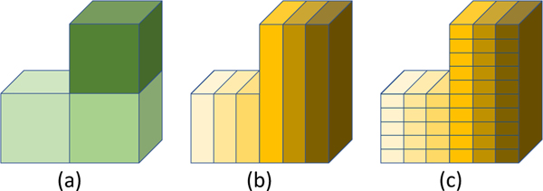
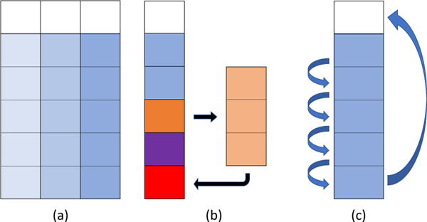
Decomposing the domain of a given MPI task into a series of ‘blocks’ is a standard strategy for improving data reuse in LBM. A simple instance of such a block decomposition is show in figure 1(a). While data reuse in distribution-based LBM propagation patterns is limited to efficient cache line usage, performance improvements for LBM and related stencil computation with blocking and tiling schemes are well documented [6], [7], [27].
Fig. 1.
(a) Domain decomposition for generic loop blocking, (b) 1D domain decomposition based on cross-sectional area of layers of blocks, (c) Division of 1D domain decomposition into layers.
For this sliding window algorithm, a 1D decomposition is performed such that the cross sectional area of each block is smaller than a given threshold selected based on the size of the CPU last level cache, as illustrated in figure 1(b). Within each block, the sliding window will sequentially perform the LBM update on all points in a layer, from the bottom layer to the top layer, before moving on the the next block. For each lattice point in a given layer, the moments {ρ, ρu, Π} are read from memory and collision is performed. Since ρ and ρuare conserved, collision is only performed on the second order tensor. Consequently, the equivalent of equations 3 and 15 takes the form:
| (17) |
| (18) |
for equilibrium tensor and non-equilibrium tensor . Instead of being written back to memory, the post-collision moments are converted from moment to distribution representation using equation 16. This post-collision distribution data is streamed into a distribution array associated with the sliding window domain, according to a scheme such as direct addressing or an indirect addressing adjacency list.
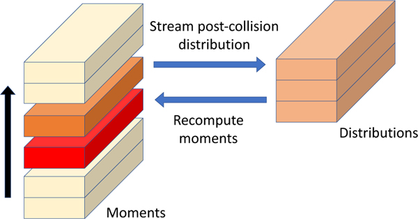
After streaming a given layer into the sliding window domain, the distribution components associated with streaming into that layer will not be complete until both the layers immediately above and below the given layer have also streamed into the sliding window domain. However, as the layers of the block are being processed from bottom to top, the layer immediately below the given layer will be completely represented in the sliding window domain. Accordingly, after performing streaming on a given layer, the subsequent step will be to recompute the moments on the layer immediately below using equations 8–10. The resulting sliding window algorithm is illustrated in figure 2.
Fig. 2.
Depiction of sliding window algorithm: Moments from a given layer (orange) undergo collision, are mapped to the distribution representation, and written to the sliding window domain according to an indirect addressing scheme (peach). Subsequently, moments for the previous layer (red) are recomputed in the sliding window domain and written back to memory.
For this propagation pattern, the moments at each lattice point will be read and written once per timestep, assuming the block size is small enough to avoid write allocates. Further, the distribution array resides entirely in cache and permits data reuse in distribution space without additional cost. However, in the typical case of multiple blocks per MPI rank, an additional challenge arises related to performing streaming across the interface between blocks. As discussed in [5], the instances of streaming between blocks can be divided into streaming ‘forward’, from the current block to a block not yet been updated this timestep, and ‘backward’, from the current block to a previously updated block.
Streaming ‘backward’ across block boundaries is addressed with recomputation: performing an additional collision operation on those lattice points and computing only those distribution components that stream into the current block. ‘Forward’ streaming is more challenging, as the previously applied update to those blocks precludes recomputation. Instead, distribution components that would stream forward across block boundaries are identified during preprocessing and they are streamed to a separate array, which is read from when the block into which they are streaming is updated. The size of this separate array will be proportional to the area of the interface between blocks.
The memory usage of the propagation pattern for the moment representation (MR) is assessed relative to two distribution representation LBM propagation patterns:
AB pattern: a fused collision and streaming kernel with two copies of the LBM distribution function.
AA pattern: a fused kernel scheme with a single copy of the LBM distribution function, but different updates for even and odd timesteps.
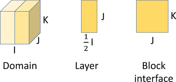
To compare the memory usage of the moment-based propagation pattern with distribution-based versions, we consider the simplified case illustrated in figure 3 of a dense cuboid geometry with I, J, and K points in each dimension, for a total of N=IJK fluid points. It is divided into 2 blocks with per layer of block, and with block interface area of JK. The lattice has Q distribution components, M moments, and R distribution components able to stream forward or backward across the block interface (for Q=19 and 27, R=5 and 9, respectively).
Fig. 3.
Illustration of layer and block interface dimensions for a simple cuboid example with two blocks.
For the common D3Q19 lattice, table 1 shows that the moment-based propagation pattern’s M=10 moments for the second-order approximation of the Navier-Stokes equations would offer a modest savings for the amount of distribution, moment, and indirect addressing memory stored per lattice site. Instead of 376 bytes/lattice site for AB and 224 for AA, as few as 156 would be required for MR if the layer and block interface data remained in cache. For the D3Q27 lattice, the reduced memory cost of the moment representation becomes more pronounced: 536 bytes per point for AB, 320 for AA, and as few as 188 for MR.
TABLE 1.
Memory requirements for AB, AA, and moment representation (MR) propagation patterns for single speed lattices.
| Component | AB | AA | MR |
|---|---|---|---|
| Distribution (double) | 2NQ | NQ | 3BQ + RJK |
| Moments (double) | 0 | 0 | MN |
| Indirect addressing (int) | N(Q-1) | N(Q-1) | NQ |
We observe that, while this study focuses on single speed lattices, regularized lattice Boltzmann has been extended to multi-speed lattices such as D3Q39 [28]. Two notable changes occur for multi-speed lattices: more than three layers would be required for the distribution space window and the inclusion of higher-order moments may result in a less favorable ratio of Q to M than D3Q19 or D3Q27.
3.2. Boundary conditions
An LBM propagation pattern for the moment representation poses a potential challenge for implementing boundary conditions because these are typically formulated in terms of the distribution f. Simple conditions such as halfway bounceback can be embedded directly into streaming without additional computational complexity. Other boundary conditions could be applied with the standard distribution representation in the sliding window domain, after the layer has been completely streamed in but before moments have been recomputed [5]. However, it would be simpler and more efficient if boundary conditions could be reformulated in the moment representation. Interest in interpreting LBM boundary conditions in terms of their moment representation dates to [29] and moment-based LBM boundary conditions have since become an active research area [30], [31].
It is straightforward to implement such moment-based boundary conditions in the moment representation, but it is less clear how existing distribution-based boundary conditions would be reformulated. In this section, we discuss recasting a distribution-based boundary condition in terms of the moment representation, without reference to the distribution. We consider the finite difference velocity gradient method from Latt et al [32] imposing a Dirichlet condition u = u0. We previously implemented this condition for inlets and outlets of blood flow simulations using the standard distribution representation [33].
3.2.1. Distribution-based scheme
In this condition, each distribution component fi at the boundary is replaced using the equilibrium distribution and strain rate tensor Sαβ:
| (19) |
The strain rate tensor is evaluated using a finite difference method with velocities from adjacent lattice sites, which are known either from streaming or from the velocity boundary condition u = u0. However, the unknown density ρ at a straight boundary lattice site is computed using the post-streaming components of the distribution as in the Zou-He scheme [34]. Without loss of generality, let us assume an xy boundary plane with the positive z-unit vector pointing out of the simulation domain. Borrowing Latt’s simple formulation [21], we may define partition ρ into
| (20) |
for , and 1. After streaming, ρ0 and ρ1 will be determined and ρ−1 unknown. Since and , then ρ is computed as
| (21) |
3.2.2. Moment-based scheme
Due to the conservation of density and momentum, the moment representation of equation 19 simplifies to a formula for computing the second-order moments,
| (22) |
using equation 21 from Latt et al [32]. Moreover, the evaluation of contributions to Sαβ for non-boundary lattice sites is simplified since velocities are trivial to recompute from ρ and ρu. However, equation 21 cannot be used to solve for density ρ because the post-streaming distribution components are not directly available.
In the moment representation, what is known at the boundary after streaming is not distribution components, but the partial sums and of the density and momentum. The necessary components of these two quantities, and can easily be rewritten in terms of the partition from equation 20:
| (23) |
Consequently, we may reformulate equation 21 in terms of equation 23 to produce a moment representation version:
| (24) |
The resulting implementation of this boundary condition in the moment representation offers modest computational advantages over the distribution representation version. Only the second-order moments are newly computed at each lattice site, instead of Q new distribution components in the distribution representation. Likewise, the evaluation of the product is eliminated.
4. CPU PERFORMANCE RESULTS
4.1. Software and hardware details
In this study, the computational performance of the propagation pattern for the moment representation (MR) is compared with the previously mentioned AB and AA distribution representation propagation patterns. The AB, AA, and MR methods are implemented in HARVEY, a LBMbased scalable application for simulating blood flow in complex vascular geometries [35]. Blood flow in vascular geometries is a common setting for assessing performance and scalability of LBM implementations (e.g., [36], [37]).
The CPU version of HARVEY uses a array of structures (AoS) data layout and is parallelized with MPI and OpenMP. As vascular geometries are typically sparse and irregular, load balancing is performed with Metis [38] and an indirect addressing adjacency list is used to reduce memory storage requirements. Validation of HARVEY for various applications is discussed in previous work (e.g., [18], [39]).
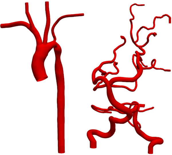
HARVEY runtime performance for the three propagation patterns is measured for Newtonian flow in two complex vascular geometries. The necessarily irregular domain decomposition of these complex geometries poses a useful test of the robustness and flexibility of the MR method. As depicted in figure 4, the aortic and cerebral vasculatures have complex shapes with varied vessel diameters. The aortic geometry has one inlet and five outlets, while the cerebral geometry has 2 inlets and 11 outlets. The finite difference velocity gradient method discussed above is used to enforce a velocity boundary condition at inlets and a pressure boundary condition at outlets. The no-slip condition is maintained elsewhere on the vessel walls using the halfway bounceback method.
Fig. 4.
Aortic (left) and cerebral (right) vasculatures used for hemodynamic simulations.
Testing was conducted on two CPU node architectures: Intel Broadwell and IBM Power9. The Intel node had two Xeon E5–2699V4 processors, with each processor having 20 cores available to the job scheduler and a shared 55 MB last level cache. The IBM node has two Power9 22Cs processors, with each processor having 21 cores available to the job scheduler and a total of 120 MB last level cache shared between core pairs. Measured memory bandwidth on each node from the STREAM’s Copy benchmark [40] is 56.9 GB/s on the Broadwell node and 227 GB/s on the Power9 node. Intel and IBM XL compilers were used for the Broadwell and Power9 architectures, respectively.
In previous work, we presented a hierarchical roofline model on the Broadwell architecture and evaluated the memory bound performance of our algorithm [5]. In the next section, we focus on a an application-focused roofline that has proven useful to characterize LBM performance in previous studies [41]. Computational performance is measured in MFLUPS (million fluid lattice updates per second). Because lattice Boltzmann implementations are typically memory bound, optimal performance MFLUPSmax can be estimated by a simple function of (1) CPU memory bandwidth BBW in bytes and (2) number of bytes transferred to and from memory to perform a fluid lattice update (bytes per FLUP, or B/F), as
| (25) |
Table 2 shows the numbers of bytes per FLUP for the three propagation patterns in this study using indirect addressing. The corresponding roofline estimates of the MFLUPSmax using equation 25 are listed in table 3.
TABLE 2.
Bytes per fluid lattice update (B/F) for propagation patterns of distribution- and moment-representations using indirect addressing, with Q distribution components and M moments in the lattice. In the third and fourth columns, the B/F formula in the second column is applied to the D3Q19 and D3Q27 lattices, respectively.
| Pattern | Bytes/FLUP (B/F) | D3Q19 B/F | D3Q27 B/F |
|---|---|---|---|
| AB | 3Q*double + (Q-1)*int | 528 | 752 |
| AA | 2Q*double + (Q-1)*int | 340 | 484 |
| MR | 2M*double + Q*int | 236 | 268 |
TABLE 3.
Estimated optimal MFLUPSmax from roofline performance model for each propagation pattern and CPU architecture, based on measured bandwidth and the bytes per FLUP computed in table 2.
| Broadwell (MFLUPS) | Power9 (MFLUPS) | |||
|---|---|---|---|---|
| Pattern | D3Q19 | D3Q27 | D3Q19 | D3Q27 |
| AB | 108 | 77 | 432 | 303 |
| AA | 167 | 118 | 671 | 471 |
| MR | 241 | 212 | 966 | 851 |
4.2. Node-level performance
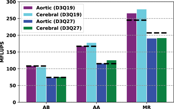
Single-node performance is shown for the Broadwell node in figure 5 for the D3Q19 and D3Q27 lattices. Excellent agreement between the performance model and the measured results is observed for both lattices using the AB and AA propagation patterns. The MR pattern also meets the roofline expectations for the D3Q19 lattice, showing the moment approach is effective in reducing data motion to and from main memory. Performance for the D3Q27 lattices with the MR pattern still greatly exceeds the AA or AB, but falls short of the roofline; there are a couple of potential reasons for this comparatively weaker performance. First, previous studies have observed slightly worse performance for D3Q27 than D3Q19 after normalizing by the number of distribution components [42]. Second, an alternate data layout such as array of structures (AoS) or array of structure of arrays (AoSoA) may deliver superior performance on larger lattices like D3Q27. Nonetheless, when averaged over the two geometries, we find performance of MR exceeds that of AA by about 56% for D3Q19 and 58% for D3Q27. As the AA propagation pattern is typically the most performant LBM scheme on CPUs [41], these speedups represents a significant improvement.
Fig. 5.
Single node performance for AB, AA, and MR propagation patterns on using the D3Q19 and D3Q27 lattices for the Broadwell node. Dashed black lines indicate estimate from roofline model.
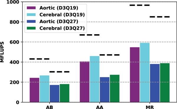
The much higher measured bandwidth on the Power9 node enables significantly higher bandwidth versus the Broadwell node. While performance does improve, MFLUPS are closer to 50–60% of the performance model, as illustrated in figure 6. We expect that a difference in threading on the two architectures may account for this difference. On the Broadwell node, the two hardware threads on each physical core were used for two OpenMP threads per core in HARVEY, which resulted in a 1.8–2x speedup versus using a single thread. However, using simultaneous multithreading on the Power9 cores with OpenMP did not improve performance. As a result, the Power9 runs were conducted with a single thread per core. Additionally, we expect that a different data layout, structure of arrays instead of array of structures, may improve performance on Power9. Nonetheless, the MR propagation pattern significantly outperforms AA for both lattices, with MFLUPS an average of 31% higher for D3Q19 and 43% higher for D3Q27.
Fig. 6.
Single node performance for AB, AA, and MR propagation patterns on using the D3Q19 and D3Q27 lattices for the Power9 node. Dashed black lines indicate estimate from roofline model.
On both architectures, simulations for the MR propagation pattern were conducted for a range of layer sizes. From this group, the best results for each geometry and lattice were used in figure 5 and 6. The dependence of MR performance on layer size is evaluated in the next section.
4.3. Layer size dependence and cache awareness
The MR propagation pattern is cache-aware in the sense that, by setting a maximum cross-sectional layer area for the block decomposition, the amount of distribution data for the sliding window domain can be fixed. However, the amount of distribution data that must remain in cache is not only a function of layer size: as noted in table 1, distribution data that streams forward across the block interface must also be temporarily stored. Moreover, the size of the forward streaming data is non-trivial: as illustrated in figure 3, it is not difficult to describe a decomposition where the data for sliding window domain and forward streaming have comparable sizes. Particularly for complex geometries, the size of the block interface can only be determined by one parameter: the dimension of the domain in which the sliding window moves (additionally, in the degenerate single block case, the area of the block interface is trivially zero). Accordingly, this section focuses on the two controllable aspects of cache awareness: 1) understanding how MR propagation pattern performance varies with maximum layer size and 2) considering how the choice of the dimension in which the sliding window moves affects distribution data size.
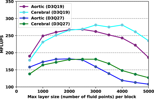
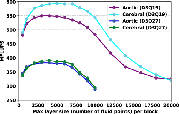
In figures 7 and 8, performance is considered as a function of maximum layer size on the Broadwell and Power9 processors, respectively. The HARVEY run configuration has one MPI rank per physical core, so the layer size indicated in these figures is the maximum layer size (measured in lattice points) for a single MPI rank. We observe that while the different geometries and resulting load balances led to modest differences in optimal node-level performance, the results of these differences are more evident in this context. The aortic geometry on Broadwell obtains near-peak performance over maximum layer sizes of 1500–3000 lattice points on D3Q19, while sustained best performance for the sparser cerebral geometry with that lattice is with 3000–4000 lattice points. A steep drop in performance results from larger layer sizes. This overall trend persists for the D3Q27 lattice, albeit with the curves being moved to the left due to this lattice having nearly 50% more distribution data at each lattice point. Due to the large last level cache on the Power9 node, near-peak performance is maintained over a wider interval, with ranges of 2000–7000 and 2000–6000 lattice points for the D3Q19 and D3Q27 lattices, respectively.
Fig. 7.
Influence of cache block size on Broadwell node performance.
Fig. 8.
Influence of cache block size on Power 9 node performance.
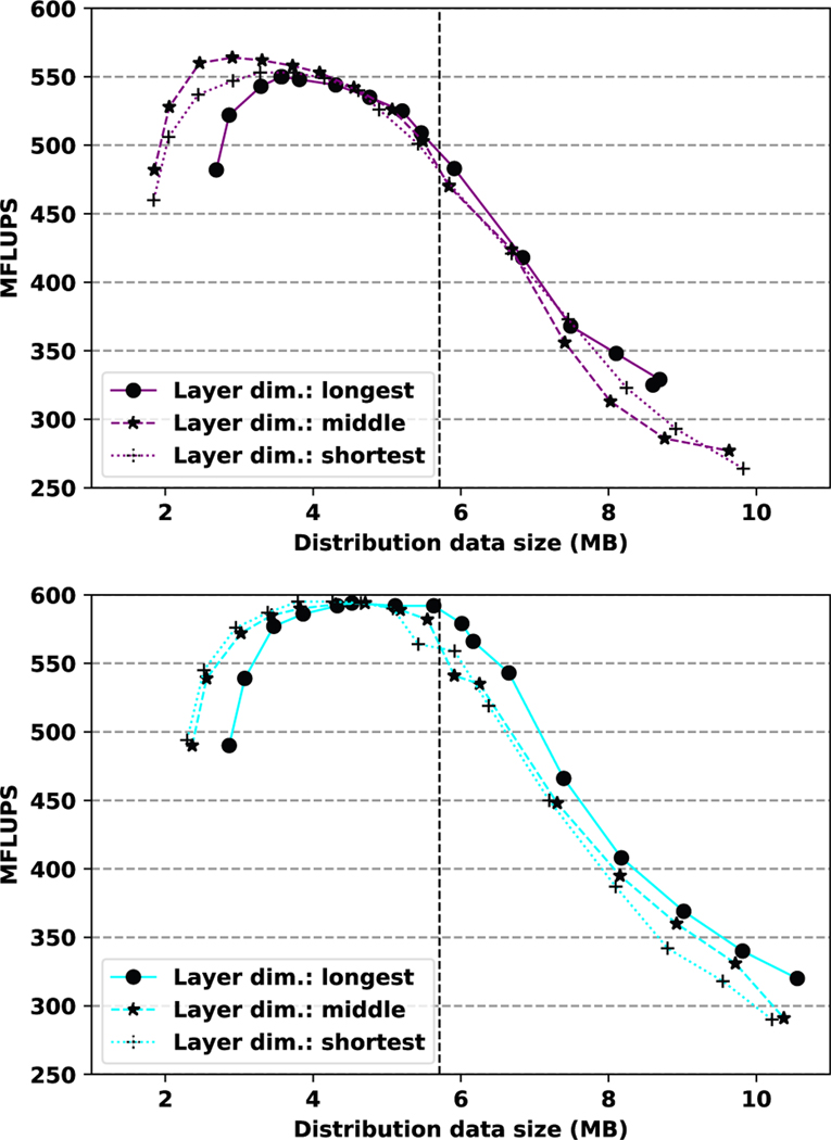
To better understand how the cache size influences performance, it is necessary to consider all distribution data, from both the sliding window and forward streaming. In figure 9, results from the D3Q19 runs in figure 8 are represented as a function of the total size of distribution data. For both geometries, a sharp drop in performance is observed when distribution data size exceeds last level cache size. However, while optimal performance for the cerebral geometry is maintained almost until the cache capacity is exhausted, the aortic geometry’s peak occurs at a somewhat smaller distribution data size.
Fig. 9.
Performance in MFLUPS as a function of distribution data size per rank on the Power9 node for the aortic (top) and cerebral (bottom) geometries and the D3Q19 lattice. Vertical dotted line indicates approximate last level cache size per physical core on the Power9 node. Layer dimension indicates whether the sliding window moves along the longest, middle, or shortest axis of computational domain of each rank.
It was expected that the most efficient configuration would be to have the sliding window moving along the longest axis of the domain. Such a configuration minimizes the number of blocks necessary for a given maximum layer size and, therefore, the number of times recomputation is performed for backward streaming across a block interface. However, using the middle or shortest axis for the sliding window has the effect of reducing the size of the block interface itself. For small layer sizes, this has the effect of significantly decreasing the distribution data size for a given layer size. Given the generous last level cache sizes on the Power9 node, only marginally better performance was observed when using the middle or shortest dimension for the sliding window. However, in environments where cache space is at a premium, the benefits of these alternative configurations may bemore clear.
4.4. Boundary conditions
The influence of boundary conditions on LBM performance varies considerably. While halfway bounceback can be embedded within an indirect addressing scheme, more complex conditions must be applied as a kernel separate from streaming. If a more complex condition, such as the finite difference velocity gradient method, were applied over the full surface of the geometry, the additional memory access and computation will influence load balance and overall runtime. Moreover, Feiger et al [33] observed that the choice of boundary condition influences time-to-solution not only in terms of the runtime of the boundary condition itself, but also in the resolution at which the simulation must be run to obtain convergence.
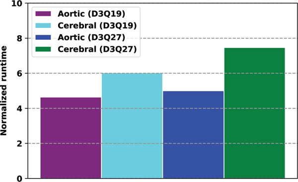
As discussed above, the moment representation of the finite difference boundary condition has the potential to improve performance versus distribution representation. Both memory accesses and floating point operations are dramatically reduced by performing equation 22 in the moment representation. In figure 10, the relative time spent applying the inlet and outlet conditions for both geometries and lattices is considered. In each case, the MR scheme is at least four times faster than AB and AA. The advantage here is two-fold: not only does the moment representation provide better performance, but it simplifies the implementation and application of the highly stable finite difference velocity gradient scheme.
Fig. 10.
Runtime of the inlets and outlets conditions for the AA pattern normalized by the MR pattern runtime on the Power 9 node.
5. MOMENT REPRESENTATION ON GPUS
GPUs have become an important architecture for high performance lattice Boltzmann simulations, due to the relative ease with which the method can be ported to GPUs and the strong performance of the method on these architectures. However, since LBM remains bandwidth bound on GPUs and problem sizes are limited by the size of global memory on GPUs, the proposed moment representation method has potential for reducing storage and improving time-to-solution on this architecture as well.
Schemes relying heavily on data reuse enabled by cache memory may map poorly to GPUs, where the larger number of threads compete to use a smaller amount of cache memory. Accordingly, a port of the moment representation method must expose a much larger degree of parallelism and make more efficient use of cache, even at the expense of other important factors such as minimizing accesses to GPU global memory. The resulting port of the moment representation method is similar to that of Matyas for fractional step lattice Boltzmann [43], but with the advantage of maintaining the standard lattice Boltzmann method without approximating exact streaming. In this section, we describe a 2D implementation of the moment representation method on a GPU and discuss performance with the D2Q9 lattice.
5.1. GPU propagation pattern
For a 2D geometry, the computational domain is decomposed in one dimension, as shown on the left side of figure 11 for the decomposition in the horizontal dimension. Each column from this decomposition is associated with a thread block. Each column is further decomposed in the axial dimension into a series of tiles, with the tile being a cross-section of the column that is one or more grid points in height. The number of threads in the thread block is the sum of the number of lattice points in the tile plus a one lattice point-wide halo in the horizontal direction. Consequently, for a tile with dimensions xt× yt, the number of threads in the thread block is (xt+ 2) × yt.
Fig. 11.
(a) Decomposition of geometry into columns, each associated with a thread block. Each column is ‘padded’, with the top tile being initially vacant. (b) For a given thread block, the post-collision distribution on a tile (orange) is written into shared memory (peach) with memory locations determined by streaming. Moments are recomputed for the previous tile (purple), but are shifted one tile below when writing back to global memory (red). (c) This shift is based on tiled circular array shifting, updated from bottom to top, with the moments of each updated tile written to the location beneath it.
At each timestep, thread blocks begin by reading from global memory the moments associated with its lattice point in the bottom tile or that tile’s halo. As in the CPU version, collision is performed and the post-collision moments are mapped to the distribution representation. The distribution components are streamed by writing them to the appropriate positions in a shared memory array using direct or indirect addressing. The shape of the shared memory array is based on the tile size, along with a one lattice point-wide halo in the vertical direction for distribution components streaming up or down out of the tile. The resulting amount for shared memory usage per thread block is:
| (26) |
double precision values. After the thread block has completed streaming and synced, post-streaming distribution values are available for all lattice points in the tile (albeit not in the halo) except for the top layer. Accordingly, moments are recomputed for all lattice points in the tile except the top layer and written back to global memory.
As reads from the halo are necessary for streaming and synchronization cannot be used to ensure that reads from other thread blocks are performed prior to writes, a single moment array cannot naively be used for reading and writing of moments. Moreover, the simple alternative – maintaining two copies of the moment array – does not reduce storage versus schemes like AA that maintain a single copy of the distribution array. Instead, tiled circular array shifting, a scheme originally described for lattice Boltzmann by Dethier et al [44] and illustrated on the right side of figure 11, is employed with an extra tile in each column for shifting. For a large problem size, this extra tile size is amortized and the effective memory usage is M moments, instead of Q distribution components, per lattice site.
After the bottom tile has been updated and written, the thread block proceeds to update the tile above until reaching the top of the column. The algorithm remains the same except with respect to the top layer in each tile. As the complete post-streaming distribution for this layer is not available until the tile above has been streamed into shared memory, it is maintained in the shared memory array until being written back to global memory with the tile above it.
The GPU propagation pattern for the moment representation differs in a two important respects from its CPU-based counterpart. First, and most notably, instead of updating blocks successively and with an explicit dependence from one to the next, each column in the GPU version is updated independently. Likewise, the complexity of forward streaming between blocks is eliminated on the GPU, replaced by redundant reads on the tile’s horizontal halo. This change exposes sufficient parallelism to make efficient use of the GPU. Second, circular array shifting replaces the simple single moment array in the CPU version. While not offering a performance advantage on the GPU, array shifting does permit the reduced use of global memory. We observe that this GPU propagation pattern could be used on CPUs as well and is well-suited for using many-core processors with large numbers of threads per MPI rank.
5.2. GPU performance analysis
To understand the performance of the MR scheme on GPUs, it is evaluated against a reference implementation of the AB propagation pattern based on the pull scheme [45]. Both the AB and MR propagation patterns are implemented in CUDA, have a structure of arrays (SoA) memory access pattern, and simulate a two dimensional channel flow with the D2Q9 lattice. The finite difference velocity gradient boundary condition from section 3.2 is used for the inlet and outlet, while halfway bounceback is applied on the channel walls. In this section, we assess performance in MFLUPS on a Nvidia V100 GPU and compare with predictions from roofline performance models.
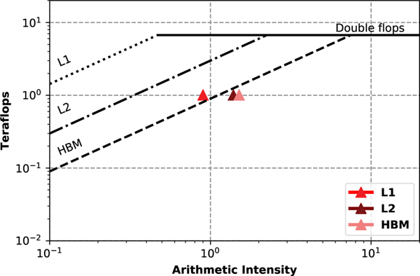
A hierarchical roofline model for the performance of the MR propagation pattern on the V100 is shown in figure 12 using the methodology from [46] and Nvidia’s nvprof profiler. The arithmetic intensity of LBM algorithms is typically low and this remains true for the MR algorithm as well. We observe that, while located in the memory bound region, HBM intensity falls somewhat short of the roofline, achieving 1.01 teraflops versus an expected 1.34. Consequently, it is clear that only about 75% of the available GPU memory bandwidth is utilized. Because of the negligible data reuse in LBM, L2 intensity is predictably close to HBM, with only a slight decrease in arithmetic intensity. On the other hand, L1 intensity should be somewhat lower due to the reuse of the distribution array in shared memory. However, we find that this decrease is exacerbated by the large number of bank conflicts occurring when storing in shared memory due to the complexity of the LBM streaming operations.
Fig. 12.
Hierarchical roofline analysis of the MR algorithm on the V100 GPU. Lines for HBM and double precision FLOPs are taken from Nvidia Nsight profiler, while those for L1 and L2 are taken from [46].
As in the previous section for CPUs, we also use an LBM performance model to estimate the ideal performance in MFLUPS [47] for both propagation patterns. Based on the results of the hierarchical roofline, we expect that this LBM performance model will overestimate performance of the MR algorithm due to bank conflicts in shared memory and the incomplete use of HBM memory bandwidth. Equation 25 is used with the hardware information from table 4 to produce the estimates in table 5. For the AB and MR patterns, there are two global memory accesses each timestep, but the sizes of the data being read and written are different. For AB, there are Q=9 double precision distribution components per lattice site, while MR pattern has M=6 moments per lattice site: density, two momenta, and the three unique components of the second order tensor. Based on the bytes/FLUP for each scheme and GPU memory bandwidth in bytes, the LBM roofline estimates MFLUPSmax are computed in table 5.
TABLE 4.
Summary of the main features of the Nvidia V100 GPU
| Frequency | 1, 455 MHz |
| CUDA cores | 5, 120 |
| SM count | 80 |
| On-chip Mem. | Shared: up to 96 KB per SM L1: up to 96 KB per SM L2: 6, 144 KB (unified) |
| Memory | HBM2 16 GB |
| Bandwidth | 900 GB/s |
| Compiler | nvcc v11.0.221 |
TABLE 5.
Estimated optimal MFLUPSmaxfrom LBM roofline performance model for a V100 GPU using direct addressing and equation 25.
| Pattern | Bytes/FLUP (B/F) | D2Q9 B/F | D2Q9 Roofline |
|---|---|---|---|
| AB | 2Q*double | 144 | 6250 |
| MR | 2M*double | 96 | 9375 |
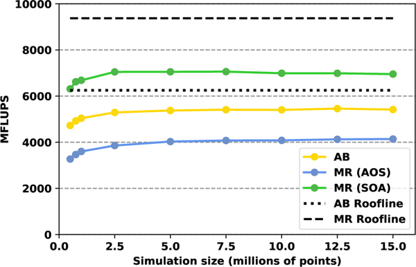
Figure 13 graphically illustrates the performance for the AB and MR GPU implementations over a range of problem sizes and in comparison with the roofline predictions. The average performance of the AB approach is about 5, 300 MFLUPS, which is approximately 85% of the theoretical peak. The average performance of the MR approach using an SoA pattern is significantly higher, achieving about 7, 000 MFLUPS, or approximately 75% of the theoretical peak performance. This matches the 75% utilization of HBM memory bandwidth mentioned above. As data access patterns in GPU memory have an important impact on GPU performance, we also consider an alternative array of structures (AoS) memory access pattern for the MR scheme. As expected, the AoS pattern significantly underperforms SoA for the MR scheme, as has been well-documented for standard lattice Boltzmann propagation patterns [45], [47], [48]. Overall, while it achieves a lower percentage of theoretical peak performance reflected in the roofline model, the MR approach is nonetheless able to achieve a much higher performance than our reference AB implementation.
Fig. 13.
Performance evaluation in MFLUPS of the AB and MR propagation patterns for D2Q9 on a V100 GPU as a function of the number of fluid points in the simulation domain.
Although we are able to accelerate the execution time of the LBM simulations by using the MR approach on GPUs, it is also important to highlight that one of the main targets of this approach is to minimize the memory requirements for simulations. For D2Q9, 6 double precision elements per lattice site are required for the MR approach, versus 9 for AA and 18 for AB. This memory reduction is important due to limited GPU memory capacity; it enables larger simulations to be run on a single GPU without incurring the performance loss associated with communication. Unlike other approaches that reduced the memory requirements for LBM simulations on GPUs [49], our MR approach is able to not only reduce the memory requirements further but also accelerate the execution of the LBM timestep itself.
6. CONCLUSION AND FUTURE WORK
In this paper, the moment representation of the regularized lattice Boltzmann method from Vardhan et al. [5] has been extended with node-level CPU performance analysis, consideration of applying boundary conditions, and a proofof-concept GPU implementation. Using the moment representation, we demonstrated significant speedups on CPU-based flow simulations in two vascular geometries versus existing methods. Moreover, we showed how an existing LBM boundary condition from the distribution representation can be formulated in terms of moments and that this reformulation improves the efficiency of applying boundary conditions. Finally, we discussed how the moment representation propagation pattern can be ported to run on a GPU and observed that the performance is superior to existing implementations while reducing memory usage.
There are several opportunities for further improving the performance of the moment representation introduced in this paper. First, constraints on updating lattice points in a particular order and a cache-aware propagation pattern are also characteristic of another optimization for time-to-solution of LBM simulations: temporal wavefront blocking [50], [51]. By performing more than one timestep per load/store, these schemes are able to maximize LBM data reuse. It appears that temporal wavefront blocking could be combined with the moment representation to further minimize memory bandwidth usage on CPUs. Second, additional work is required to more fully understand how memory layouts impact performance for the GPU version. We will address optimization of the GPU moment representation scheme and its 3D formulation in future work. Finally, while this study considered only projection-based LBM regularization, the overall approach can be extended to the increasingly important recursive regularization scheme [52] without significant modifications. Recursive regularization offers further improvements in stability while maintaining the reduced memory bandwidth requirements of our projection-based moment representation.
ACKNOWLEDGMENTS
This work was supported by the LDRD Program of Oak Ridge National Laboratory, managed by UT-Battelle, LLC. Research reported in this publication was supported by the National Institutes of Health under award number 1U01CA253511. The content is solely the responsibility of the authors and does not necessarily represent the official views of the National Institutes of Health. This work was also supported by American Heart Association Predoctoral Fellowship and ACM/IEEE-CS George Michael Memorial High Performance Computing Fellowship. This research used resources of the Oak Ridge Leadership Computing Facility, which is a DOE Office of Science User Facility supported under Contract DE-AC05-00OR22725. This work was performed under the auspices of the U.S. Department of Energy by Lawrence Livermore National Laboratory under Contract DE-AC52-07NA27344.
This manuscript has been authored by UT-Battelle, LLC under Contract No. DE-AC05-00OR22725 with the U.S. Department of Energy. The United States Government retains and the publisher, by accepting the article for publication, acknowledges that the United States Government retains a nonexclusive, paid-up, irrevocable, world-wide license to publish or reproduce the published form of this manuscript, or allow others to do so, for United States Government purposes. The Department of Energy will provide public access to these results of federally sponsored research in accordance with the DOE Public Access Plan (http://energy.gov/downloads/doe-public-access-plan).
Biography

John Gounleyis a computational scientist in the Biostatistics and Multiscale Systems Group within the Computational Sciences and Engineering Division at Oak Ridge National Laboratory. He received a PhD in computational and applied mathematics from Old Dominion University in 2014. His research focuses on algorithms and scalability for biomedical simulations and data.

Madhurima Vardhan is a PhD candidate at the Department of Biomedical Engineering at Duke University. She received her MS degree in Biomedical Engineering from Duke University in 2015. Her current research activities focus on studying cardiovascular diseases by simulating underlying arterial physiology with 3D patientspecific simulations on leadership-scale supercomputers.

Erik W. Draeger is the Deputy Director of Application Development for the Exascale Computing Project, as well as the Scientific Computing group leader at the Center for Applied Scientific Computing (CASC) at Lawrence Livermore National Laboratory. He received a PhD in theoretical physics from the University of Illinois, Urbana-Champaign in 2001 and has over a decade of experience developing scientific applications to achieve maximum scalability and time to solution on next-generation architectures.

Pedro Valero-Lara received his B.S. and M.S. degree in computer science from the Universidad of Castilla-La Mancha (Spain), in 2009 and 2010, respectively, and the Ph.D. degree in computer science and applied mathematics from the Complutense University of Madrid (Spain) in 2015. Currently, he is a Computer Scientist at Oak Ridge National Laboratory (ORNL). He was Senior Research Engineer at Cray, where he led the efforts of the Cray LibSci-ACC library. Also, he was a Recognized Researcher and the founder and PI of the Math Libraries unit at the Barcelona Supercomputing Center (BSC) in Spain. His research interest includes high performance and scientific computing.

Shirley V. Moore received her Ph.D. in Computer Sciences from Purdue University in 1990. She is currently an Associate Professor in the Computer Science Department at the University of Texas at El Paso. She has previously been a researcher at Oak Ridge National Laboratory and at the Innovative Computing Laboratory at the University of Tennessee. Her research interests are in the area of performance analysis and optimization for heterogeneous high performance computing systems, and she has published over fifty peer-reviewed publications in this area. She has participated in several areas of the U.S. Department of Energy Exascale Computing Project, including hardware evaluation, proxy applications, application assessment, and GAMESS computational chemistry project.

Amanda Randlesis the Alfred Winborne and Victoria Stover Mordecai Assistant Professor of Biomedical Sciences at Duke University. She received her Ph.D. in Applied Physics and Master’s Degree in Computer Science from Harvard University. She obtained her B.A. in Computer Science and Physics from Duke University. Her research interests include high performance computing, scientific computing, computational fluid dynamics, and modeling biomedical phenomena.
Contributor Information
John Gounley, Computational Sciences and Engineering Division at Oak Ridge National Laboratory..
Madhurima Vardhan, Department of Biomedical Engineering at Duke University..
Erik W. Draeger, Center for Applied Scientific Computing at Lawrence Livermore National Laboratory.
Pedro Valero-Lara, Computer Science and Mathematics Division at Oak Ridge National Laboratory..
Shirley V. Moore, Department of Computer Science at the University of Texas at El Paso.
Amanda Randles, Department of Biomedical Engineering at Duke University..
REFERENCES
- [1].Sadeghi R, Shadloo MS, Hopp-Hirschler M, Hadjadj A, and Nieken U, “Three-dimensional lattice Boltzmann simulations of high density ratio two-phase flows in porous media,” Computers & Mathematics with Applications, vol. 75, no. 7, pp. 2445–2465, 2018. [Google Scholar]
- [2].Klassen A, Scharowsky T, and Korner C, “Evaporation model¨ for beam based additive manufacturing using free surface lattice Boltzmann methods,” Journal of Physics D: Applied Physics, vol. 47, no. 27, p. 275303, 2014. [Google Scholar]
- [3].Latt J, Coreixas C, Beny J, and Parmigiani A, “Efficient supersonic flow simulations using lattice Boltzmann methods based on numerical equilibria,” Philosophical Transactions of the Royal Society A, vol. 378, no. 2175, p. 20190559, 2020. [DOI] [PMC free article] [PubMed] [Google Scholar]
- [4].Succi S, Amati G, Bernaschi M, Falcucci G, Lauricella M, and Montessori A, “Towards exascale lattice Boltzmann computing,” Comput. Fluids, 2019. [Google Scholar]
- [5].Vardhan M, Gounley J, Hegele LA, Draeger EW, and Randles A, “Moment representation in the lattice Boltzmann method on massively parallel hardware,” in Proceedings of the International Conference for High Performance Computing, Networking, Storage and Analysis. ACM, 2019, p. 1. [Google Scholar]
- [6].Pohl T, Kowarschik M, Wilke J, Iglberger K, and Rude U, ¨ “Optimization and profiling of the cache performance of parallel lattice Boltzmann codes,” Parallel Process. Lett, vol. 13, no. 04, pp. 549–560, 2003. [Google Scholar]
- [7].Wellein G, Zeiser T, Hager G, and Donath S, “On the single processor performance of simple lattice Boltzmann kernels,” Comput. Fluids, vol. 35, no. 8–9, pp. 910–919, 2006. [Google Scholar]
- [8].Mattila K, Hyvaluoma J, Rossi T, Aspn M¨ as, and J. Westerholm, ¨ “An efficient swap algorithm for the lattice Boltzmann method,” Comput. Phys. Commun, vol. 176, no. 3, pp. 200–210, 2007. [Google Scholar]
- [9].Bailey P, Myre J, Walsh SD, Lilja DJ, and Saar MO, “Accelerating lattice Boltzmann fluid flow simulations using graphics processors,” in International Conference on Parallel Processing. IEEE, 2009, pp. 550–557. [Google Scholar]
- [10].Geier M. and Schoenherr M, “Esoteric twist: an efficient inplace streaming algorithmus for the lattice Boltzmann method on massively parallel hardware,” Computation, vol. 5, no. 2, p. 19, 2017. [Google Scholar]
- [11].Wittmann M, Zeiser T, Hager G, and Wellein G, “Comparison of different propagation steps for lattice Boltzmann methods,” Comput. Math. Appl, vol. 65, no. 6, pp. 924–935, 2013. [Google Scholar]
- [12].Martys NS and Hagedorn JG, “Multiscale modeling of fluid transport in heterogeneous materials using discrete Boltzmann methods,” Mater. Struct, vol. 35, no. 10, pp. 650–658, 2002. [Google Scholar]
- [13].Vidal D, Roy R, and Bertrand F, “A parallel workload balanced and memory efficient lattice-Boltzmann algorithm with single unit BGK relaxation time for laminar Newtonian flows,” Comput. Fluids, vol. 39, no. 8, pp. 1411–1423, 2010. [Google Scholar]
- [14].Matyka M, “Memory-efficient lattice Boltzmann method for low Reynolds number flows,” arXiv preprint arXiv:1912.09327, 2019. [Google Scholar]
- [15].Argentini R, Bakker A, and Lowe C, “Efficiently using memory in lattice Boltzmann simulations,” Future Gener. Comp. Sy, vol. 20, no. 6, pp. 973–980, 2004. [Google Scholar]
- [16].Succi S, “Lattice Boltzmann beyond Navier-Stokes: where do we stand?” in AIP Conference Proceedings, vol. 1786, no. 1. AIP Publishing, 2016, p. 030001. [Google Scholar]
- [17].Montessori A, Lauricella M, La Rocca M, Succi S, Stolovicki E, Ziblat R, and Weitz D, “Regularized lattice Boltzmann multicomponent models for low capillary and Reynolds microfluidics flows,” Comput. Fluids, vol. 167, pp. 33–39, 2018. [Google Scholar]
- [18].Hegele L Jr, Scagliarini A, Sbragaglia M, Mattila K, Philippi P, Puleri D, Gounley J, and Randles A, “High-Reynolds-number turbulent cavity flow using the lattice Boltzmann method,” Phys. Rev. E, vol. 98, no. 4, p. 043302, 2018. [Google Scholar]
- [19].Mattila KK, Philippi PC, and Hegele LA Jr, “High-order regularization in lattice-Boltzmann equations,” Phys. Fluids, vol. 29, no. 4, p. 046103, 2017. [Google Scholar]
- [20].Latt J. and Chopard B, “Lattice Boltzmann method with regularized pre-collision distribution functions,” Math. Comput. Simul, vol. 72, no. 2–6, pp. 165–168, 2006. [Google Scholar]
- [21].Latt J, “Hydrodynamic limit of lattice Boltzmann equations,” Ph.D. dissertation, University of Geneva, 2007. [Google Scholar]
- [22].Kruger T, Kusumaatmaja H, Kuzmin A, Shardt O, Silva G, ¨ and Viggen EM, “The lattice Boltzmann method,” Springer International Publishing, vol. 10, no. 978–3, pp. 4–15, 2017. [Google Scholar]
- [23].Coreixas C, Chopard B, and Latt J, “Comprehensive comparison of collision models in the lattice Boltzmann framework: Theoretical investigations,” Physical Review E, vol. 100, no. 3, p. 033305, 2019. [DOI] [PubMed] [Google Scholar]
- [24].d’Humieres D, Ginzburg I, Krafczyk M, Lallemand P, and L.-S.` Luo, “Multiple–relaxation–time lattice Boltzmann models in three dimensions,” Philos. Trans. R. Soc. A, vol. 360, no. 1792, pp. 437–451, 2002. [DOI] [PubMed] [Google Scholar]
- [25].Shu C, Niu X, Chew Y-T, and Cai Q, “A fractional step lattice Boltzmann method for simulating high Reynolds number flows,” Math. Comput. Simul, vol. 72, no. 2–6, pp. 201–205, 2006. [Google Scholar]
- [26].Succi S, “Lattice Boltzmann 2038,” EPL (Europhysics Letters), vol. 109, no. 5, p. 50001, 2015. [Google Scholar]
- [27].Williams S, Carter J, Oliker L, Shalf J, and Yelick K, “Lattice Boltzmann simulation optimization on leading multicore platforms,” in 2008 IEEE International Symposium on Parallel and Distributed Processing. IEEE, 2008, pp. 1–14. [Google Scholar]
- [28].Zhang R, Shan X, and Chen H, “Efficient kinetic method for fluid simulation beyond the Navier-Stokes equation,” Phys Rev E, vol. 74, no. 4, p. 046703, 2006. [DOI] [PubMed] [Google Scholar]
- [29].Bennett S, Asinari P, and Dellar PJ, “A lattice Boltzmann model for diffusion of binary gas mixtures that includes diffusion slip,” Int. J. Numer. Meth. Fl, vol. 69, no. 1, pp. 171–189, 2012. [Google Scholar]
- [30].Allen R. and Reis T, “Moment-based boundary conditions for lattice Boltzmann simulations of natural convection in cavities,” Prog. Comput. Fluid Dy, vol. 16, no. 4, pp. 216–231, 2016. [Google Scholar]
- [31].Krastins I, Kao A, Pericleous K, and Reis T, “Moment-based boundary conditions for straight on-grid boundaries in three dimensional lattice Boltzmann simulations,” Int. J. Numer. Methods Fluids, 2020. [Google Scholar]
- [32].Latt J, Chopard B, Malaspinas O, Deville M, and Michler A, “Straight velocity boundaries in the lattice Boltzmann method,” Phys. Rev. E, vol. 77, no. 5, p. 056703, 2008. [DOI] [PubMed] [Google Scholar]
- [33].Feiger B, Vardhan M, Gounley J, Mortensen M, Nair P, Chaudhury R, Frakes D, and Randles A, “Suitability of lattice Boltzmann inlet and outlet boundary conditions for simulating flow in image-derived vasculature,” Int. J. Numer. Method Biomed. Eng, vol. 35, no. 6, p. e3198, 2019. [DOI] [PMC free article] [PubMed] [Google Scholar]
- [34].Zou Q. and He X, “On pressure and velocity boundary conditions for the lattice Boltzmann BGK model,” Phys. Fluids, vol. 9, no. 6, pp. 1591–1598, 1997. [Google Scholar]
- [35].Randles A, Kale V, Hammond J, Gropp W, and Kaxiras E, “Performance analysis of the lattice Boltzmann model beyond Navier-Stokes,” in Parallel & Distributed Processing (IPDPS), 2013 IEEE 27th International Symposium on. IEEE, 2013, pp. 1063–1074. [Google Scholar]
- [36].Godenschwager C, Schornbaum F, Bauer M, Kostler H, and¨ Rude U, “A framework for hybrid parallel flow simulations with¨ a trillion cells in complex geometries,” in SC’13: Proceedings of the International Conference on High Performance Computing, Networking, Storage and Analysis. IEEE, 2013, pp. 1–12. [Google Scholar]
- [37].Randles A, Draeger EW, Oppelstrup T, Krauss L, and Gunnels JA, “Massively parallel models of the human circulatory system,” in Proceedings of the International Conference for High Performance Computing, Networking, Storage and Analysis. ACM, 2015, p. 1. [Google Scholar]
- [38].Karypis G. and Kumar V, “A fast and high quality multilevel scheme for partitioning irregular graphs,” SIAM J. Sci. Comput, vol. 20, no. 1, pp. 359–392, 1998. [Google Scholar]
- [39].Gounley J, Chaudhury R, Vardhan M, Driscoll M, Pathangey G, Winarta K, Ryan J, Frakes D, and Randles A, “Does the degree of coarctation of the aorta influence wall shear stress focal heterogeneity?” in 2016 38th Annual International Conference of the IEEE Engineering in Medicine and Biology Society (EMBC). IEEE, 2016, pp. 3429–3432. [DOI] [PMC free article] [PubMed] [Google Scholar]
- [40].McCalpin JD et al. , “Memory bandwidth and machine balance in current high performance computers,” IEEE Computer Society Technical Committee on Computer Architecture (TCCA) newsletter, vol. 1995, pp. 19–25, 1995. [Google Scholar]
- [41].Wittmann M, Haag V, Zeiser T, Kostler H, and Wellein G, “Lattice Boltzmann benchmark kernels as a testbed for performance analysis,” Comput. Fluids, vol. 172, pp. 582–592, 2018. [Google Scholar]
- [42].Shet AG, Sorathiya SH, Krithivasan S, Deshpande AM, Kaul B, Sherlekar SD, and Ansumali S, “Data structure and movement for lattice-based simulations,” Physical Review E, vol. 88, no. 1, p. 013314, 2013. [DOI] [PubMed] [Google Scholar]
- [43].Matyas A, “Fractional step lattice Boltzmann methods with coarse corrective steps,” Comput. Fluids, vol. 187, pp. 60–68, 2019. [Google Scholar]
- [44].Dethier G, de Marneffe P-A, and Marchot P, “Lattice Boltzmann simulation code optimization based on constant-time circular array shifting,” Procedia Comput. Sci, vol. 4, pp. 1004–1013, 2011. [Google Scholar]
- [45].Valero-Lara P, Pinelli A, and Prieto-Mat´ıas M, “Accelerating solid-fluid interaction using lattice-Boltzmann and immersed boundary coupled simulations on heterogeneous platforms,” in Proceedings of the International Conference on Computational Science, ICCS 2014, Cairns, Queensland, Australia, 10–12 June, 2014, ser. Procedia Computer Science, vol. 29. Elsevier, 2014, pp. 50–61. [Google Scholar]
- [46].Yang C, Kurth T, and Williams S, “Hierarchical roofline analysis for gpus: Accelerating performance optimization for the nersc9 perlmutter system,” Concurrency and Computation: Practice and Experience, vol. 32, no. 20, p. e5547, 2020. [Google Scholar]
- [47].Valero-Lara P, Igual FD, Prieto-Mat´ıas M, Pinelli A, and Favier J, “Accelerating fluid-solid simulations (lattice-Boltzmann & immersed-boundary) on heterogeneous architectures,” J. Comput. Sci, vol. 10, pp. 249–261, 2015. [Google Scholar]
- [48].Herschlag G, Lee S, Vetter JS, and Randles A, “GPU data access on complex geometries for D3Q19 lattice Boltzmann method,” in 2018 IEEE International Parallel and Distributed Processing Symposium (IPDPS). IEEE, 2018, pp. 825–834. [Google Scholar]
- [49].Valero-Lara P, “Reducing memory requirements for large size LBM simulations on GPUs,” Concurr. Comput. Pract. Exp, vol. 29, no. 24, 2017. [Google Scholar]
- [50].Wellein G, Hager G, Zeiser T, Wittmann M, and Fehske H, “Efficient temporal blocking for stencil computations by multicoreaware wavefront parallelization,” in 2009 33rd Annual IEEE International Computer Software and Applications Conference, vol. 1. IEEE, 2009, pp. 579–586. [Google Scholar]
- [51].Fu Y, Li F, Song F, and Zhu L, “Designing a parallel memoryaware lattice Boltzmann algorithm on manycore systems,” in 2018 30th International Symposium on Computer Architecture and High Performance Computing (SBAC-PAD). IEEE, 2018, pp. 97–106. [Google Scholar]
- [52].Malaspinas O, “Increasing stability and accuracy of the lattice Boltzmann scheme: recursivity and regularization,” arXiv preprint arXiv:1505.06900, 2015. [Google Scholar]


