Abstract
In this study, we investigated the effects of adhesive tape structure, adhesive tape thickness (30, 60, and 80 μm), and bonding time (5 and 15 seconds) on the bonding of inflexible and flexible substrates. We performed microchannel bonding by using a manual scraper press or a hot press machine. Rapid prototyping and mass production capabilities were achieved in the dry adhesive tape bonding of polymer microfluidic systems with both the aforementioned approaches. With process control, 95.16% and 99.53% bonding coverage could be achieved for the inflexible and flexible substrates, respectively, by using a manual scraper press. When using a press machine, the bonding coverage could be further enhanced to 99.24% for the inflexible substrates and 99.81% for the flexible substrates. Due to the viscoelastic nature of the adhesive layer in the adhesive tapes, we observed Saffman–Taylor finger and air bubble formation around the microchannel under high pumping pressure. The results indicated that the probability of Saffman–Taylor finger formation was lower and the bonding pressure was higher when using the thinner adhesive tape than when using thicker tape. Moreover, due to their rigidity, the inflexible substrates exhibited a higher bonding strength than the flexible substrates did. Bonding stability tests indicated that the bonded substrates had high bonding quality and bonding strength under long-term storage of up to 60 days.
We investigated dry adhesive bonding of thermoplastic microfluidics. The bonding performance is correlated to the air bubble encapsulation and Saffman–Taylor finger formation phenomena at the interface.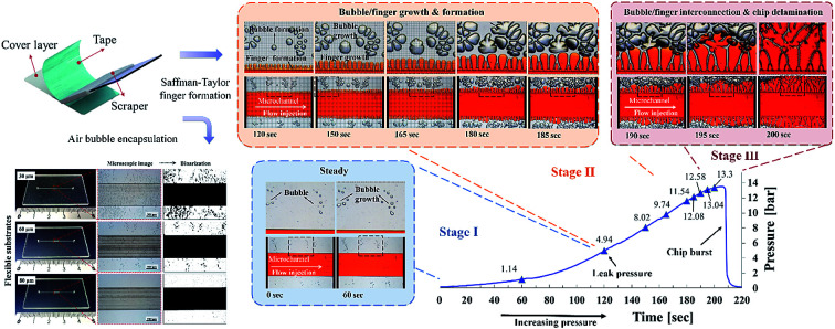
Introduction
Microfluidic systems (also called lab-on-a-chip or micro total analysis systems) are miniaturized devices with microscale fluidic components or electronics. Microfluidics has been widely applied in various fields, including for biomedical, pharmaceutical, and energy applications.1–3 Compared with conventional silicon or glass-based microfluidic devices,4,5 thermoplastics have emerged as more attractive materials due to their rigid and simple structure, low cost, and ease of disposal.6,7 The fabrication of thermoplastic microfluidic devices involves front-end microchannel fabrication and back-end microchannel bonding.8 From the fabrication point of view, the front-end process is well-developed and adaptable to industrial mass production. Microchannels can be generated through rapid prototyping methods, such as CNC milling or laser ablation for quick proof-of-concept. It can also be transferrable to commercial mass production methods such as injection molding or hot embossing massively produce the microchannel at high throughput. For back-end bonding, it is still the bottleneck that determines the success of thermoplastic microfluidics and requires further development.
The bonding methods of thermoplastic microfluidics are generally categorized as direct or indirect bonding methods.9 Most thermoplastic microfluidic research has been conducted using direct bonding approaches. Thermal fusion, or thermoplastic bonding,10,11 is one of the most common methods for sealing a microchannel. Thermoplastic substrates are heated above the glass transition (Tg) temperature to seal bonding pairs. Microchannels tend to distort or collapse unless the heat and pressure are carefully controlled. To avoid microchannel distortion, various surface-assisted methods have been developed. For example, UV/ozone12 and O2 plasma13 involve using mercury UV lamps or plasma to increase the surface energy for enabling thermoplastic bonding below Tg.12 Solvent-assisted methods involve using solvents to dissolve the polymer surface for sealing.14 Welding methods involve the use of laser,15 microwave,16 or ultrasonic17,18 energy for locally fusing the bonding interface. These bonding methods have been successfully demonstrated in various microfluidic applications. However, they have certain limitations, such as a long process time, the requirement of additional processing steps and facilities, and a low fabrication yield, which create problems for the commercial production of microfluidic devices.
Compared with direct bonding methods, indirect bonding methods require additional materials at the bonding interface. Adhesive bonding is the most widely used indirect bonding method in microfluidics. Adhesive bonding can be categorized as “wet” or “dry.” Wet adhesive bonding usually involves the use of wax,19 SU-8,20 or UV curable epoxy21,22 for gluing the surface. Despite its simplicity, wet adhesive bonding has several disadvantages. Liquid adhesives may easily reflow into the microchannel and clog the channel after curing. Moreover, uneven adhesive application may result in poor bonding yield. Sacrificial microchannels,23 capture microchannels,24 micropillars,21 interstitial microchannels,25 and capillarity-assisted microchannels26,27 can avoid the channel clogging concerns; however, these require special layout designs.
Dry adhesive bonding involves the use of tapes for bonding microfluidic devices. Compared with other thermoplastic bonding methods, dry adhesive tape bonding is the most straightforward, reliable, high-throughput, and cost-effective approach for sealing microchannels.8 Various adhesive tapes are commercially available for the mass production of microfluidic devices. Moreover, dry adhesive exhibits good bonding capability with heterogeneous materials. The bonding of thermoplastic with PDMS, glass, and metal-coated substrates has been demonstrated.28,29 Dry adhesive is also capable of multifunction integration30 and reversible sealing.31 Due to these advantages, dry adhesive bonding has been applied in various microfluidic applications including droplet-based microfluidics,32 electrowetting microdevice,33,34 chip-based electrophoresis,35 electrochemical biosensing,36 microarray immunoassay device,37 and optical biochips.38 Surface chemistry and biocompatibility is one of the critical considerations for dry adhesive bonding in microfluidic applications. With appropriate tape selection, dry adhesive bonding exhibits good biocompatibility. With numerous demonstration, dry adhesive bonding methods have been proved to be used in various biological applications, such as oral cancer biomarker sensors,39 nucleic acid extraction,28 creatine kinase-myocardial band immunoassays,40 DNA separation,41 DNA melting analysis,42 DNA amplification,43 and Madin–Darby canine kidney cell cultures.44 With the development of wearable microfluidics,45,46 multilayer40 and flexible-layer bonding47 have also been demonstrated. Because of its aforementioned advantages, dry adhesive bonding is an attractive method for microfluidics. Li recent reported the influence of adhesive bonding parameters on the bonding ratio48 and found that a soft press head can effectively prevent air bubbles from forming at the interface, thus enabling better quality.
Despite its usefulness in microfluidics, the dry adhesive bonding mechanism has only discussed to a limited extent in microfluidics and requires detailed explored. In this study, we investigated dry adhesive bonding phenomena for microfluidics. We investigated the effects of critical processes on the bonding performance for flexible and inflexible substrates. We explored the correlations of air bubble encapsulation and Saffman–Taylor finger phenomena with bonding performance.
Experiment
Materials and reagent
Adhesive tapes were obtained from 3M Taiwan Ltd. (Taipei, Taiwan). The tapes comprised 3M Double-Coated PET Tapes (8000 series) with thicknesses of 30, 60, and 80 μm; 3M Adhesive Transfer Tapes 81702/25 μm; and 3M Adhesive Transfer Tapes with adhesive 300LSE 9471LE/58 μm. The adhesive tapes exhibited weak hydrophobic behaviour (appendix S1.1). An optical-grade polymethyl methacrylate (PMMA) sheet (2 mm thick, CM-205X Chi Mei Corporation, Taipei Taiwan) was purchased from Foursun Tech Inc. (Tainan, Taiwan). An optical polycarbonate (PC) film (0.25 mm thick) was purchased from Tai-Jau Enterprise (Taoyuan, Taiwan). A stainless-steel tube (20G/0.9 mm, SUS304) was purchased from Profession Technology Co., Ltd. (Taoyuan, Taiwan). A microtungsten carbide drill bit (MDR-0.85 mm) was purchased from Tun-Hwa Electronic Material Co., Ltd. (Taichung, Taiwan). A two-flute end mill (diameter: 0.2 mm) was obtained from Taiwan Microdrill Co., Ltd. (New Taipei, Taiwan). Liquid nitrogen was procured from Chian Hong Gas Co., Ltd. (Taoyuan, Taiwan), and ethanol (95%) was purchased from Min Yung Co., Ltd. (Taoyuan, Taiwan).
Microchannel fabrication and the dry adhesive bonding
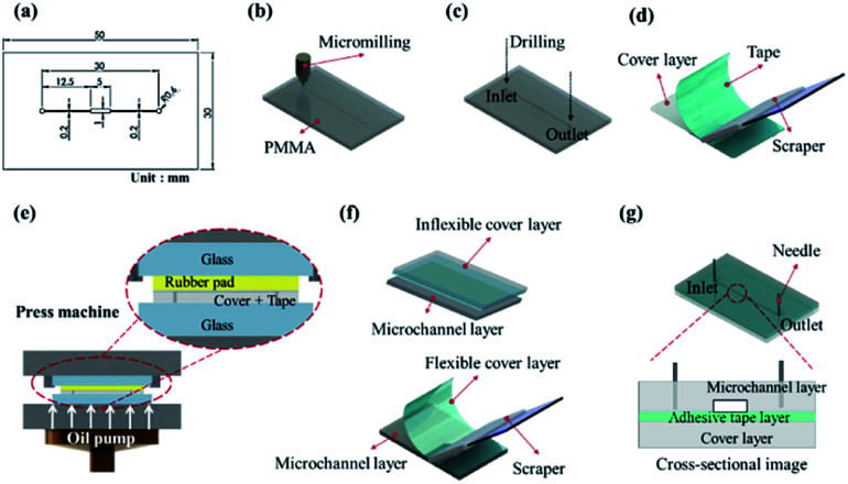
The microchannel in the dry adhesive bonding experiment is displayed in Fig. 1a. The microchannel consisted of a microchamber 5 × 1 mm2 in size that had 200 μm-wide microchannels on each side. The fabrication process was initiated using a 0.2 mm-diameter end mill bit to engrave a 100 μm-deep microchannel on the PMMA substrate (Fig. 1b). Next, 1.2 mm-diameter inlet and outlet ports (Fig. 1c) were drilled using a micromilling machine (Roland EGX-400, Roland DGA Corporation). An ultrasonic bath (Ultrasonic Cleaner, Delta D150 Hi-Sun instrument Co., Ltd.) was used to remove PMMA particles and debris. Subsequently, N2 blow drying was conducted. Adhesive tape was applied to another cover layer by using a scraper (Fig. 1d). And a pressure of 1 kg cm−2 was applied for approximately 10 seconds by using a press machine sandwiched between a rubber pad (Automatic Hot Press Molding machine HT-1, Ray Cheng Enterprise Co., Ltd.) to ensure that the adhesive layer was uniformly attached to the cover layer (Fig. 1e). In our experiment, we tested different bonding conditions for the bonding of the microchannel to the inflexible cover layer (2 mm PMMA/adhesive tape) and flexible cover layer (0.25 μm PC/adhesive tape) by either press machine or manual scraper (Fig. 1f). Finally, surgical needles were inserted as the fluidic inlet and outlet for fluid injection and pressure tests (Fig. 1g).
Fig. 1. Schematic of the microchannel fabrication procedures: (a) microchannel design, (b) microchannel milling, (c) inlet and outlet port drilling, (d) application of adhesive tape by using a scraper, (e) press bonding by using a hot press, (f) bonding with a cover layer, and (g) insertion of surgical needles.
Bonding performance evaluation
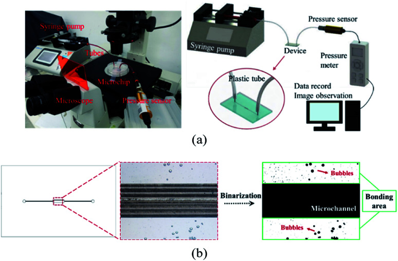
We evaluated the performance of adhesive tape bonding by investigating the air bubble encapsulation, Saffman–Taylor finger formation, and bonding strength. As displayed in Fig. 2a, a microchip was placed in an inverted microscope (Nikon Eclipse Ti, Nikon Corp. Tokyo, JP). The fluid inlet was connected to a syringe pump (Kd Scientific Legato 210, KD Scientific Inc., MA, USA) to inject red food dye. The outlet was connected to a pressure sensor to measure the bonding pressure. The bubble percentage was obtained by dividing the bubble area by the bonding area (eqn (1)). Images of the bonding interface were captured using the inverted microscope (Fig. 2b). The images were then binarized and calculated using Image J.
 |
1 |
Fig. 2. (a) Photograph (left) and schematic (right) of the bonding strength measurement setup and (b) binarization image analysis of the bubble ratio (magnification 40×).
Results and discussion
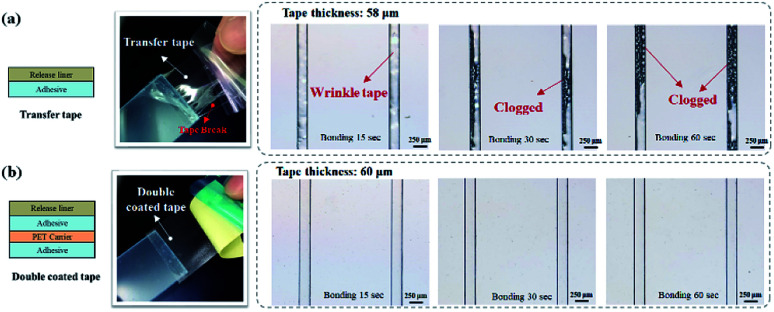
In dry adhesive bonding, several factors, such as the tape structure, adhesive thickness, and bonding process parameters, influence the sealing quality. We first evaluated the performance of two major tape structures, namely the transfer tape and double-coated tape, for sealing the microfluidic device. As displayed in Fig. 3a, because the transfer tape only consisted of a thin release liner holding the adhesive layer, the adhesive layer easily broke and also tended to clog the microchannel after bonding. The double-coated tape was more stable than the transfer tape because the double-coated tape had a carrier between the adhesive layers. The bonding results indicated that no microchannel clogging occurred when the double-coated tape was used (Fig. 3b). Thus, we focus on investigating the effects of bonding process parameters by using different double-coated adhesive tapes. Both 2 mm-thick and 250 μm-thick cover substrates were tested to represent inflexible and flexible microfluidic devices. The 250 μm-thick PC film is selected as our flexible cover layer since it is relatively soft and flexible thermoplastic material compare to thin PMMA sheet.
Fig. 3. Microchannel bonding with a (a) transfer tape and (b) double-coated tape under different bonding conditions.
Dry adhesive bonding on inflexible and flexible substrates by manual scraper press
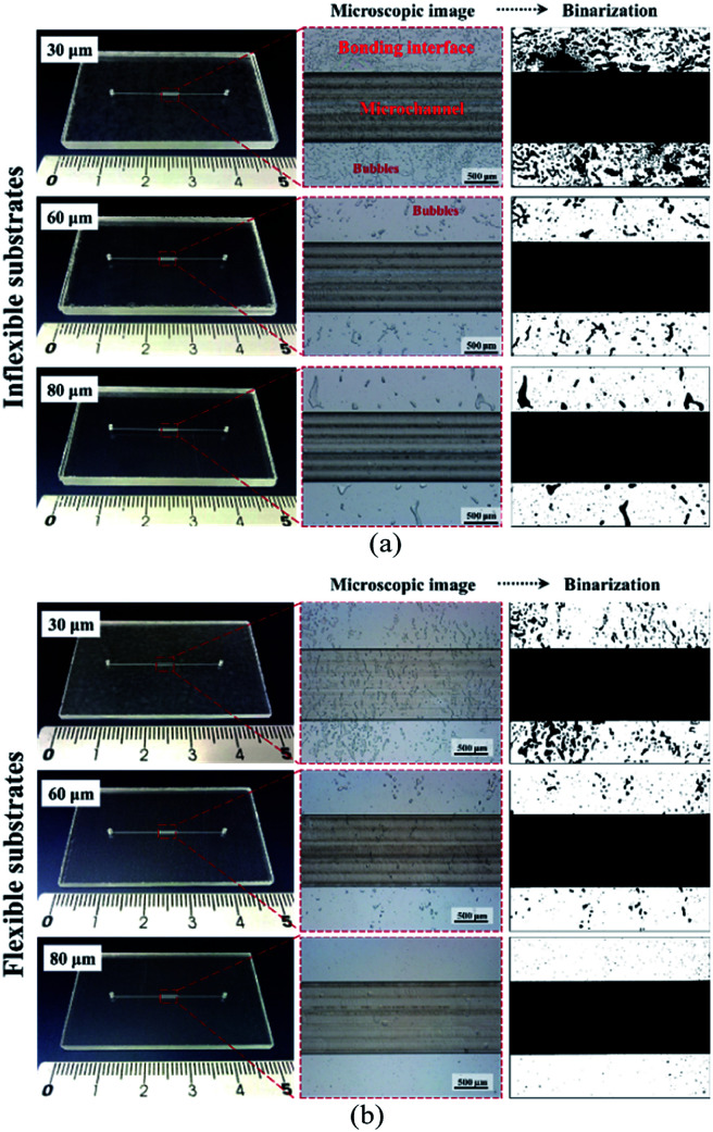
In dry adhesive bonding, critical process parameters, such as the adhesive layer thickness, bonding pressure, and bonding time, are highly correlated with bonding quality. Most current double-coated adhesive tapes are pressure-sensitive. With a simple hand or scraper press, two substrates can be held. Because of its simplicity, we first used a manual scraper for device bonding. Tape thicknesses of 30, 60, and 80 μm were used for evaluating the bonding process on inflexible and flexible cover substrates. As displayed in Fig. 4, all the microchannels were successfully bonded without chip separation or clogging; however, microbubbles were observed at the bonding interface. For a thin dry adhesive tape (30 μm thickness) bonded to an inflexible substrate, numerous bubbles were formed. For thicker dry adhesive tapes (60 and 80 μm thick), fewer bubbles were observed at the interface for bonding on the inflexible and flexible substrates. Fewer bubbles were observed for adhesive tape bonding on the flexible substrates (Fig. 4b) than for that on the flexible substrates (Fig. 4a). When 80 μm-thick adhesive tape was bonded to a flexible substrate, the smallest amount of bubbles formed at the interface.
Fig. 4. Photographs and microscope images of the microchannel bonding interface on (a) 2 mm-thick inflexible substrates and (b) 250 μm-thick flexible cover substrates during bonding with 30, 60, and 80 μm-thick double-coated tapes by using a scraper press.
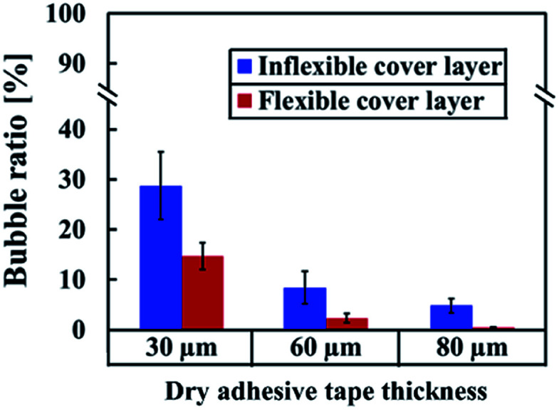
As shown in Fig. 5, bonding achieved with thin adhesive tapes and inflexible substrates resulted in more air bubbles being encapsulated at the bonding interface. This result was obtained because the adhesive layer is an intrinsically viscoelastic material. Under the application of pressure, the viscous adhesive adhered to the cover substrate and filled the polymer surface defects. During this time, the deformation energy was partially eliminated by the viscous dissipation effect. When released the pressure, the viscous adhesive reflowed to a static stage and formed bonds (chemical nature of the adhesives) between two substrates. At this time, air was encapsulated at the bonding interface, which resulted in the formation of bubbles. For thicker dry adhesive tapes, higher viscoelastic adhesive deformation occurred but fewer bubbles formed at the interface. Consequently, the bubble ratio decreased when the thickness of the adhesive layer increased. On an inflexible cover substrate, the bubble ratio decreased from 28.75 ± 6.77 for a 30 μm-thick tape to 8.44 ± 3.27 for a 60 μm-thick tape and 4.84 ± 1.46 for an 80 μm-thick tape. Compared with the inflexible substrates, the flexible substrates exhibited higher elastic–plastic deformation but fewer bubbles at the interface. Moreover, the bubble ratio decreased with the thickness (from 14.74 ± 2.65 for a 30 μm-thick tape to 2.36 ± 0.95 for a 60 μm-thick tape and 0.47 ± 0.07 for an 80 μm-thick tape).
Fig. 5. Bubble ratio percentage for the bonding of 30, 60, and 80 μm-thick adhesive tapes on inflexible and flexible substrates by using a scraper press. Error bars were obtained from three individual measurements.
Dry adhesive bonding on inflexible and flexible substrate by press machine and the time effects of bonding
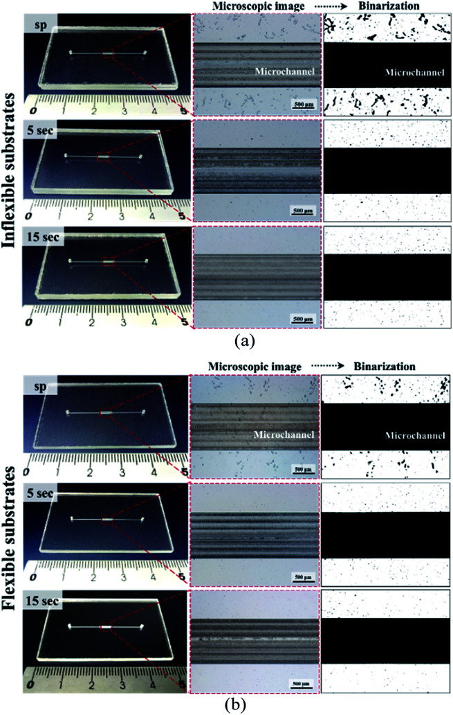
Although microfluidic chips can be bonded manually by using scrapers, a pressing machine provides better control of the process parameters, thereby resulting in a better fabrication yield. The use of a pressing machine also enables the mass production of bonded devices. Furthermore, because viscoelastic flow is a time-dependent phenomenon, the balance between stress and strain requires dwelling time to build up under a given force. Increasing the dwelling time during the bonding process may have a pronounced influence on the adhesive motion at the bonding interface. Prolonged contact between adhesives and a substrate under pressure enables the formation of strong chemical bonds at the interface. Therefore, we examined the time effects of bonding and compared the results obtained from using a hot press machine with those obtained from using a scraper press. The minimum bonding pressure for the press machine was selected as 1.05 kg cm−2. Fig. 6 illustrates images for the bonding of 60 μm-thick dry adhesive tapes with the flexible and inflexible substrates (images for bonding of the 30 and 80 μm-thick tapes are displayed in Fig. S2 and S3,† respectively). Fig. 6 and Table S1† indicate that the bubble ratio decreased with increasing bonding time. For the inflexible cover substrates (Fig. 6a), the bubble ratio percentage decreased from 8.44 ± 3.27 to 0.47 ± 0.18 with increasing tape thickness. For the flexible cover substrates (Fig. 6b), the bubble ratio percentage decreased from 2.36 ± 0.95 to 0.25 ± 0.06 with increasing tape thickness. Compared with manual press conditions, the air bubble encapsulation percentage decreased by approximately 27.03%, 7.97%, and 4.08% for bonding of the inflexible substrates with 30, 60, and 80 μm-thick adhesive tapes, respectively, and approximately 14.19%, 0.28%, and 4.08% for bonding of the flexible substrates with 30, 60, and 80 μm-thick adhesive tapes, respectively.
Fig. 6. Images of the microchannel bonding interface on a (a) 2 mm-thick inflexible substrate and (b) 0.25 mm-thick flexible cover substrate when using a scraper press (sp), for 5 and 15 seconds. Dry adhesive tape thickness: 60 μm and pressure: 1.05 kg cm−2.
Saffman–Taylor finger formation and bonding strength
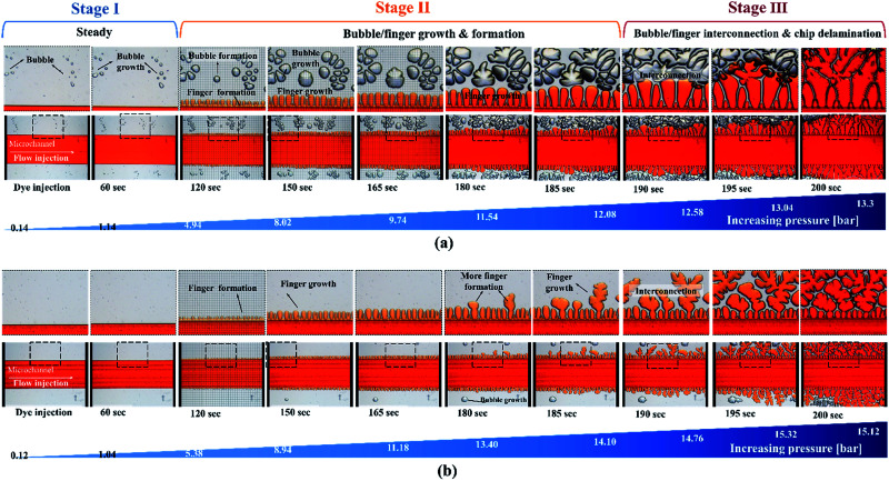
In contrast to other types of thermoplastic bonding, delamination usually begins with crack propagation at the interface. We found that the Saffman–Taylor finger plays a critical role in the debonding mechanism. We categorized the Saffman–Taylor debonding phenomenon into three stages: stage I, steady condition; stage II, bubble/finger formation and growth; and stage III, bubble/finger interconnection and chip delamination. As displayed in Fig. 7, with increasing injection flow rate, the operation pressure reached a threshold point and the Saffman–Taylor finger began to form. We defined this threshold point as the “leak pressure,” at which the flow began to “leak” into the finger-shaped dead volumes. In the steady condition (stage I), no fluidic leakage was observed from the microchannel. However, we observed some bubble growth at the bonding interface with increasing pressure. Above the leak pressure (stage II), the Saffman–Taylor finger began to form around the microchannel. In this stage, the air bubbles at the interface and fingers around the edge continued to grow with increasing pressure. Some bubbles also began to generate at the interface. When the fingers and bubbles were merged and interconnected (stage III), the fluid from the microchannel penetrated the bonding interface and flowed out from the microchip and case chip. Videos of the dry adhesive bonding phenomena are presented in V1.1–V1.5 of the ESI.†
Fig. 7. Saffman–Taylor finger formation at the bonding interface. The microfluidic devices were bonded (a) using a scraper press and (b) using a hot press for 15 seconds. Red food dye was injected into the devices for observation under an inverted microscope. The adhesive tape thickness was 60 μm.
The debonding mechanism correlated with the Saffman–Taylor finger and air bubble growth were observed in all of the process conditions, as presented in Table S1.† The air bubble ratio at the bonding interface was influenced by the bonding (leak) pressure. With proper dry adhesive bonding process control, air bubble encapsulation at the bonding interface can be minimized; thus, an increased leak pressure can be obtained for the same adhesive layer thickness. Fig. 6 indicates that less bubble or finger formation and interconnection occurred for 15 second bonding with the hot press (Fig. 6b) than for bonding with the scraper press (Fig. 6a). Moreover, a higher leak pressure (3.93 bar) was observed when using the hot press than when using the scraper press (2.96 bar).
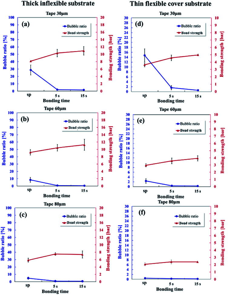
Saffman–Taylor finger and bubble formation around the microchannel creates dead volumes and trap fluidics, which may potentially result in cross-contamination or flow instability for microfluidic applications. Therefore, because of the unique Saffman–Taylor debonding phenomena in dry adhesive bonding, the leak pressure should be used instead of the chip delamination or burst pressure to determine the bonding strength. Fig. 8 displays the bonding strength (red line) and bubble ratio (blue line) with different tape thicknesses (30, 60, and 80 μm) for the inflexible and flexible substrates. Because low finger and bubble formation occurred under hot press bonding for 15 seconds, a higher bonding strength was obtained in this condition than under hot press bonding for 5 seconds or scraper press bonding. Bonds formed with the inflexible substrates (Fig. 8a–c) were stronger than those formed with the flexible substrates (Fig. 8d–f) because the thick inflexible substrates were considerably more rigid than were the thin flexible substrates. When a pumping pressure acts on the microchannel, a thicker substrate is subject to less bending. Thus, the possibility of Saffman–Taylor finger or air bubble formation decreases, which leads to increased operating pressures.
Fig. 8. Bubble ratio and bonding strength of the 30 μm – thick (a and d), 60 μm – thick (b and e), and 80 μm – thick (c and f) adhesive tapes on the thick inflexible substrates (a–c) and thin flexible substrates when using a manual scraper press and under hot pressing for 5 and 15 seconds.
The effects of the adhesive thickness can be analyzed by examining the Saffman–Taylor viscous finger formation in the Hele–Shaw cell. The dry adhesive bonding interface is analogous to a Hele–Shaw cell model in which a less viscous fluid (water in the microchannel) is injected into a more viscous fluid material (viscoelastic adhesive layer) between two parallel substrates (the microchannel and cover layer). According to Darcy's law,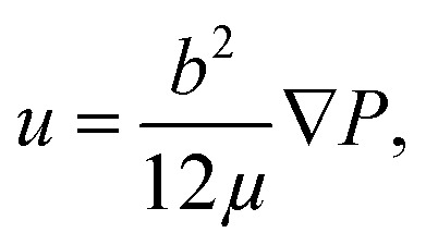 where u is the motion (velocity) of the viscous adhesive, b is the gap of the viscous layer (adhesive layer gap), μ is the viscosity, and P is the flow pumping pressure from the microchannel. The flow pumping pressure is inversely proportional to the adhesive layer thickness. Therefore, for a thin adhesive layer, high driving pressure can be achieved without Saffman–Taylor finger formation causing high leakage pressure, as displayed in Fig. 8. Consequently, stronger bonding can be achieved when using thin adhesive tape than when using thick adhesive tape.
Dry adhesive tape bonding stability
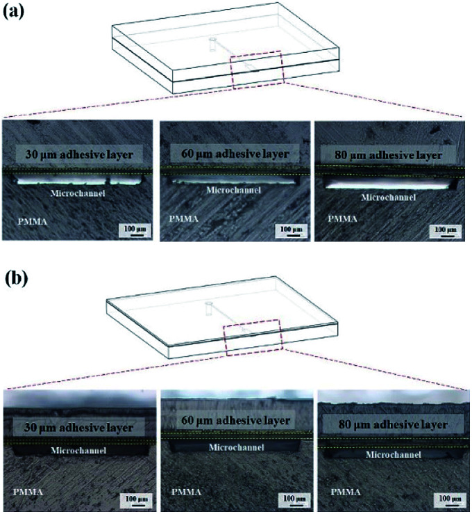
Bonding stability is a critical factor in microfluidics and can be categorized as geometric stability and time stability. In the cross-sectional images of the inflexible (Fig. 9a) and flexible (Fig. 9b) substrates, no microchannel clogging or distortion was observed. Thus, dry adhesive bonding had good geometric stability with low thermal-induced microchannel distortion.
Fig. 9. Cross-sectional images of the microchannels of (a) an inflexible substrate and (b) a flexible substrate after 15 second bonding with the press machine when using 30, 60, and 80 μm-thick adhesive tapes.
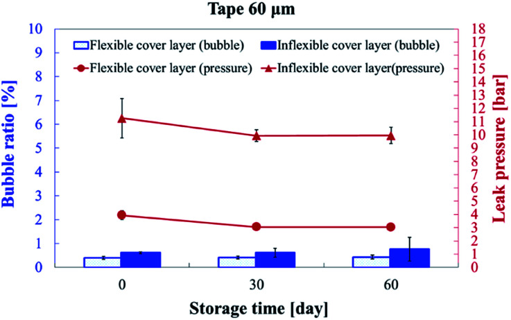
For the commercialization of microfluidic devices, the time stability for good shelf life is a crucial factor. Thus, we subjected the substrates to long-term storage of up to 60 days at room temperature to evaluate the bonding quality. Fig. 10 presents the bubble ratio percentage and leak pressure for the inflexible and flexible substrates at days 0, 30, and 60. The bubble ratio marginally increased from 0.61% ± 0.04% (day 0) to 0.76% ± 0.50% (day 60) and from 0.40% ± 0.06% (day 0) to 0.43% ± 0.08% (day 60) for the inflexible and flexible substrates, respectively. The bonding strength marginally degraded from 11.26 ± 1.49 bar (day 0) to 9.96 ± 0.62 bar (day 60) and from 3.93 ± 0.36 bar (day 0) to 3.04 ± 0.02 bar (day 60) for the inflexible and flexible substrates, respectively.
Fig. 10. Bubble ratio percentage and leak pressure on day 0, 30, and 60 of storage. The microchannel was bonded with 60 μm-thick tape by using a hot press for 15 seconds.
Conclusions
The bonding of thermoplastic microfluidics is an important process that determines the success of microfluidic devices. Among the various thermoplastic bonding methods, dry adhesive tape bonding provides the following unique advantages: simple process, low cost, robustness, high throughput, and bonding at low temperature and pressure that can be achieved in a short time. In this study, we investigated the effects of adhesive tape structures (transfer tape and double-coated tape), adhesive tape thicknesses (30, 60, and 80 μm), and bonding time (5 and 15 seconds) on the bonding of inflexible and flexible substrates. We performed microchannel bonding by using a manual scraper press and hot press machine. Rapid prototype bonding and mass production capabilities were achieved in the dry adhesive tape bonding of polymer microfluidic systems with both of the aforementioned approaches. With process control, 95.16% (4.84% air bubble percentage at the bonding interface) and 99.53% (0.47% air bubble percentage at the bonding interface) bonding coverage could be achieved for the inflexible and flexible substrates, respectively, by using a simple manual scraper press. With the use of a hot press machine, the bonding coverage could be further enhanced to 99.24% for the inflexible substrates and 99.81% for the flexible substrates.
Due to the viscoelastic nature of the adhesive layer in the adhesive tapes, Saffman–Taylor finger or air bubble formation was observed around the microchannel edges when the pumping pressure was increased. The Saffman–Taylor debonding phenomenon can be characterized as comprising the following stages: stage I, steady condition; stage II, bubble/finger formation and growth; and stage III, bubble/finger interconnection and chip delamination. Above the threshold bonding (leak) pressure, the Saffman–Taylor finger grew and interconnected with the air bubbles at the bonding interface, which eventually resulted in chip delamination. Results indicate 30 μm-thick adhesives start to form Saffman–Taylor finger at higher pressure resulting in better bonding pressures than thicker adhesives. Moreover, because of their rigidity, the inflexible substrates exhibited a higher bonding strength than the flexible substrates did. The maximum bonding strength was 11.26 bar for the inflexible substrates and 4.98 bar for the flexible substrates. Bonding stability tests were also performed in this study. These tests indicated that the bonded substrates had high bonding quality and bonding strength under long-term storage of up to 60 days.
Conflicts of interest
There are no conflicts to declare.
Supplementary Material
Acknowledgments
The authors would like to thank the Ministry of Science and Technology (MOST), Taiwan, for financially supporting this project under Grant No. MOST 107-2221-E-008-029 and 108-2221-E-008-028-MY2.
Electronic supplementary information (ESI) available. See DOI: 10.1039/d0ra05876a
Notes and references
- Sackmann E. K. Fulton A. L. Beebe D. J. Nature. 2014;507:181–189. doi: 10.1038/nature13118. [DOI] [PubMed] [Google Scholar]
- Modestino M. A. Rivas D. F. Hashemi S. M. H. Gardeniers J. G. E. Psaltis D. Energy Environ. Sci. 2016;9:3381–3391. doi: 10.1039/C6EE01884J. [DOI] [Google Scholar]
- Cui P. Wang S. J. Pharm. Anal. 2019;9:238–247. doi: 10.1016/j.jpha.2018.12.001. [DOI] [PMC free article] [PubMed] [Google Scholar]
- Abgrall P. Gué A. M. J. Micromech. Microeng. 2007;17:R15–R49. doi: 10.1088/0960-1317/17/5/R01. [DOI] [Google Scholar]
- Hwang J. Cho Y. H. Park M. S. Kim B. H. International Journal of Precision Engineering and Manufacturing. 2019;20:479–495. doi: 10.1007/s12541-019-00103-2. [DOI] [Google Scholar]
- Becker H. Locascio L. E. Talanta. 2002;56:267–287. doi: 10.1016/S0039-9140(01)00594-X. [DOI] [PubMed] [Google Scholar]
- Liu K. Fan Z. H. Analyst. 2011;136:1288–1297. doi: 10.1039/C0AN00969E. [DOI] [PMC free article] [PubMed] [Google Scholar]
- Tsao C.-W. Micromachines. 2016;7:225. doi: 10.3390/mi7120225. [DOI] [PMC free article] [PubMed] [Google Scholar]
- Tsao C.-W. DeVoe D. L. Microfluid. Nanofluid. 2008;6:1–16. doi: 10.1007/s10404-008-0361-x. [DOI] [Google Scholar]
- Roy S. Yue C. Y. Wang Z. Y. Anand L. Sens. Actuators, B. 2012;161:1067–1073. doi: 10.1016/j.snb.2011.12.011. [DOI] [Google Scholar]
- Sun Y. Kwok Y. C. Nguyen N.-T. J. Micromech. Microeng. 2006;16:1681–1688. doi: 10.1088/0960-1317/16/8/033. [DOI] [Google Scholar]
- Tsao C. W. Hromada L. Liu J. Kumar P. DeVoe D. L. Lab Chip. 2007;7:499–505. doi: 10.1039/B618901F. [DOI] [PubMed] [Google Scholar]
- Shinohara H. Mizuno J. Shoji S. Sens. Actuators, A. 2011;165:124–131. doi: 10.1016/j.sna.2010.04.006. [DOI] [Google Scholar]
- Chen P.-C. Duong L. H. Sens. Actuators, B. 2016;237:556–562. doi: 10.1016/j.snb.2016.06.135. [DOI] [Google Scholar]
- Kim J. Xu X. F. J. Laser Appl. 2003;15:255–260. doi: 10.2351/1.1585085. [DOI] [Google Scholar]
- Yussuf A. A. Sbarski I. Hayes J. P. Solomon M. Tran N. J. Micromech. Microeng. 2005;15:1692–1699. doi: 10.1088/0960-1317/15/9/011. [DOI] [Google Scholar]
- Kistrup K. Poulsen C. E. Hansen M. F. Wolff A. Lab Chip. 2015;15:1998–2001. doi: 10.1039/C5LC00174A. [DOI] [PubMed] [Google Scholar]
- Zhang Z. Luo Y. Wang X. Zheng Y. Zhang Y. Wang L. Microsyst. Technol. 2010;16:533–541. doi: 10.1007/s00542-010-1027-7. [DOI] [Google Scholar]
- Diaz-Gonzalez M. Baldi A. Anal. Chem. 2012;84:7838–7844. doi: 10.1021/ac301512f. [DOI] [PubMed] [Google Scholar]
- Salvo P. Verplancke R. Bossuyt F. Latta D. Vandecasteele B. Liu C. Vanfleteren J. Microfluid. Nanofluid. 2012;13:987–991. doi: 10.1007/s10404-012-1011-x. [DOI] [Google Scholar]
- Chen P.-C. Liu Y.-M. Chou H.-C. J. Micromech. Microeng. 2016;26:045003. doi: 10.1088/0960-1317/26/4/045003. [DOI] [Google Scholar]
- Chen P.-C. Chen C.-C. Sens. Actuators, A. 2017;258:105–114. doi: 10.1016/j.sna.2017.03.006. [DOI] [Google Scholar]
- Dang F. Shinohara S. Tabata O. Yamaoka Y. Kurokawa M. Shinohara Y. Ishikawa M. Baba Y. Lab Chip. 2005;5:472–478. doi: 10.1039/B417398H. [DOI] [PubMed] [Google Scholar]
- Riegger L. Strohmeier O. Faltin B. Zengerle R. Koltay P. J. Micromech. Microeng. 2010;20:087003. doi: 10.1088/0960-1317/20/8/087003. [DOI] [Google Scholar]
- Lu C. Lee L. J. Juang Y.-J. Electrophoresis. 2008;29:1407–1414. doi: 10.1002/elps.200700680. [DOI] [PubMed] [Google Scholar]
- Matellan C. del Río Hernández A. E. Sci. Rep. 2018;8:6971. doi: 10.1038/s41598-018-25202-4. [DOI] [PMC free article] [PubMed] [Google Scholar]
- Shah J. J. Geist J. Locascio L. E. Gaitan M. Rao M. V. Vreeland W. N. Anal. Chem. 2006;78:3348–3353. doi: 10.1021/ac051883l. [DOI] [PubMed] [Google Scholar]
- Kim J. Surapaneni R. Gale B. K. Lab Chip. 2009;9:1290–1293. doi: 10.1039/B818389A. [DOI] [PubMed] [Google Scholar]
- Tan H. Y. Loke W. K. Nguyen N.-T. Sens. Actuators, B. 2010;151:133–139. doi: 10.1016/j.snb.2010.09.035. [DOI] [Google Scholar]
- Nath P. Fung D. Kunde Y. A. Zeytun A. Branch B. Goddard G. Lab Chip. 2010;10:2286–2291. doi: 10.1039/C002457K. [DOI] [PubMed] [Google Scholar]
- Ren Y. Ray S. Liu Y. Sci. Rep. 2019;9:4824. doi: 10.1038/s41598-019-41208-y. [DOI] [PMC free article] [PubMed] [Google Scholar]
- Thompson C. S. Abate A. R. Lab Chip. 2013;13:632–635. doi: 10.1039/C2LC40978J. [DOI] [PubMed] [Google Scholar]
- He F. Nugen S. R. Microfluid. Nanofluid. 2014;16:879–886. doi: 10.1007/s10404-013-1317-3. [DOI] [Google Scholar]
- Tsai Y. C. Jen H. P. Lin K. W. Hsieh Y. Z. J. Chromatogr. A. 2006;1111:267–271. doi: 10.1016/j.chroma.2005.12.003. [DOI] [PubMed] [Google Scholar]
- Chang Y. J. You H. Anal. Methods. 2019;11:1229–1236. doi: 10.1039/C8AY02642D. [DOI] [Google Scholar]
- Kim J. Shin Y. Song S. Lee J. Kim J. Sens. Actuators, B. 2014;202:60–66. doi: 10.1016/j.snb.2014.05.009. [DOI] [Google Scholar]
- Liu Y. S. Wang W. Hu W. H. Lu Z. S. Zhou X. Q. Li C. M. Biomed. Microdevices. 2011;13:769–777. doi: 10.1007/s10544-011-9547-1. [DOI] [PubMed] [Google Scholar]
- Patko D. Martonfalvi Z. Kovacs B. Vonderviszt F. Kellermayer M. Horvath R. Sens. Actuators, B. 2014;196:352–356. doi: 10.1016/j.snb.2014.01.107. [DOI] [Google Scholar]
- Weigum S. E. Floriano P. N. Christodoulides N. McDevitt J. T. Lab Chip. 2007;7:995–1003. doi: 10.1039/B703918B. [DOI] [PubMed] [Google Scholar]
- Kim J. Shin Y. Song S. Lee J. Kim J. Sens. Actuators, B. 2014;202:60–66. doi: 10.1016/j.snb.2014.05.009. [DOI] [Google Scholar]
- Dang F. Tabata O. Kurokawa M. Ewis A. A. Zhang L. Yamaoka Y. Shinohara S. Shinohara Y. Ishikawa M. Baba Y. Anal. Chem. 2005;77:2140–2146. doi: 10.1021/ac0485031. [DOI] [PubMed] [Google Scholar]
- Greer J. Sundberg S. O. Wittwer C. T. Gale B. K. J. Micromech. Microeng. 2007;17:2407–2413. doi: 10.1088/0960-1317/17/12/003. [DOI] [Google Scholar]
- Liu Y. J. Rauch C. B. Stevens R. L. Lenigk R. Yang J. N. Rhine D. B. Grodzinski P. Anal. Chem. 2002;74:3063–3070. doi: 10.1021/ac020094q. [DOI] [PubMed] [Google Scholar]
- Serra M. Pereiro I. Yamada A. Viovy J. L. Descroix S. Ferraro D. Lab Chip. 2017;17:629–634. doi: 10.1039/C6LC01319H. [DOI] [PubMed] [Google Scholar]
- Yeo J. C. Kenry Lim C. T. Lab Chip. 2016;16:4082–4090. doi: 10.1039/C6LC00926C. [DOI] [PubMed] [Google Scholar]
- Chen G. Zheng J. Liu L. Xu L. Small Methods. 2019;3:1900688. doi: 10.1002/smtd.201900688. [DOI] [Google Scholar]
- Kim B. J. Lee D. Lee J. Yang S. J. Micromech. Microeng. 2015;25:017003. doi: 10.1088/0960-1317/25/1/017003. [DOI] [Google Scholar]
- Li J. Liang C. Zhang H. Liu C. Micro Nano Lett. 2017;12:90–94. doi: 10.1049/mnl.2016.0478. [DOI] [Google Scholar]
Associated Data
This section collects any data citations, data availability statements, or supplementary materials included in this article.


