Highlights
Cellulose aerogel with vertically oriented structure was obtained by constructing a vertically aligned SiC nanowires/BN network via the ice template assisted strategy.
The thermal conductivity of the composite in the vertical direction reaches 2.21 W m−1 K−1 at a low hybrid filler loading of 16.69 wt%, which was increased 890% compared to pure epoxy.
The composite exhibits good electrically insulating with a volume electrical resistivity about 2.35×10¹¹ Ω cm, and displays excellent electromagnetic wave absorption performance.
Supplementary Information
The online version contains supplementary material available at 10.1007/s40820-022-00863-z.
Keywords: Epoxy, Ice template, Vertical alignment, Thermal conductivity, Multifunctionality
Abstract
With the innovation of microelectronics technology, the heat dissipation problem inside the device will face a severe test. In this work, cellulose aerogel (CA) with highly enhanced thermal conductivity (TC) in vertical planes was successfully obtained by constructing a vertically aligned silicon carbide nanowires (SiC NWs)/boron nitride (BN) network via the ice template-assisted strategy. The unique network structure of SiC NWs connected to BN ensures that the TC of the composite in the vertical direction reaches 2.21 W m−1 K−1 at a low hybrid filler loading of 16.69 wt%, which was increased by 890% compared to pure epoxy (EP). In addition, relying on unique porous network structure of CA, EP-based composite also showed higher TC than other comparative samples in the horizontal direction. Meanwhile, the composite exhibits good electrically insulating with a volume electrical resistivity about 2.35 × 10¹¹ Ω cm and displays excellent electromagnetic wave absorption performance with a minimum reflection loss of − 21.5 dB and a wide effective absorption bandwidth (< − 10 dB) from 8.8 to 11.6 GHz. Therefore, this work provides a new strategy for manufacturing polymer-based composites with excellent multifunctional performances in microelectronic packaging applications.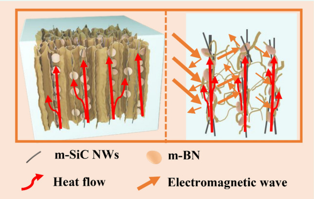
Supplementary Information
The online version contains supplementary material available at 10.1007/s40820-022-00863-z.
Introduction
With the innovation of the third-generation semiconductor technology, electronic equipment has shown a development trend of multi-function, miniaturization and integration [1–4]. As a result, a large amount of heat generated inside the equipment continue to accumulate, which seriously affects its reliability and service life [5]. Polymer materials have been widely used in the sealing and interface bonding of various electronic devices due to their excellent mechanical properties, good insulation and unique chemical stability [6–8]. However, the thermal conductivity (TC) of polymer materials is generally low (usually no more than 0.5 W m−1 K−1), which limits their wide-ranging applications in the microelectronic packaging industry [9–11]. How to improve the TC of polymer materials and make them better apply to the field of thermal management has become an important problem that needs to be solved urgently [12].
Compared with the difficulty to change the molecular chain structure of the intrinsic polymer to improve TC, it is simple and practical to add a filler with high TC into the polymer [13–15]. Generally, such thermally conductive fillers mainly include metal oxides (e.g., Al2O3, ZnO and MgO) [16], metal particles (e.g., Cu, Zn and Ag) [17], aluminum nitride (AlN) [18], boron nitride (BN) [19], silicon carbide (SiC) [20], graphene [21] and carbon nanotubes [22], etc. Among them, BN is considered to be the most promising two-dimensional material because of its low density, excellent electrical insulation, oxidation resistance and chemical stability properties [23, 24]. Unfortunately, a large amount of BN are often needed in the composite to achieve a satisfactory heat dissipation effect due to the existence of interface thermal resistance between polymer matrix and fillers, which is bound to sacrifice the excellent toughness of the matrix and the mechanical properties of the composite [25, 26]. Therefore, it is of great significance to use less BN fillers to obtain composites with a better TC in high power density electronic devices.
In recent years, compared with simple blending, two strategies of driving the horizontally orientation of BN [27] and building a three-dimensional (3D) BN thermally conductive network [28] can effectively construct heat conduction paths to improve the TC at a low BN content. In the former orientation applications, composites mostly appear in the form of films. For example, Yang et al. [29] fabricated polyvinyl alcohol/boron nitride composite film with high in-plane TC (19.99 W m−1 K−1) via the combination of electrostatic spinning and hot-pressing technique. Wu et al. [30] reported a BN nanosheet/polymer composite film with superior in-plane TC of around 200 W m−1 K−1 and extremely low through-plane TC of 1.0 W m−1 K−1. Although these film-like composites have considerable in-plane TC, the heat dissipation of microelectronic devices is mainly through the rapid transfer of accumulated heat energy from the heat source to the heat sink in a short vertical direction [31, 32]. The TC of the film-like composites in the vertical direction is quite low, which hinders their large-scale use in actual production. The latter uses fillers to establish a spatially interconnected thermally conductive network structure to improve the overall TC of the composite [33]. Chen et al. [34] prepared BN-polyvinylidene difluoride (PVDF) 3D scaffold by removing the sodium chloride salt template method and found that the TC of the final epoxy/BN-PVDF was 1.227 W m−1 K−1. Zhou et al. [35] synthesized a 3D interconnective cross-linking polystyrene (c-PS)/BN composite foam with a TC of 1.28 W m−1 K−1 and found that the composite foams exhibited low density and dielectric constants. Although the 3D heat conduction paths constructed by BN in the matrix improves the overall TC of the bulk composite to a certain extent, the TC in the vertical direction cannot be effectively improved by relying on BN alone [36].
Therefore, on one hand, one-dimensional materials (e.g., carbon nanotubes, silver nanowire and SiC nanowire) as a thermally conductive bridge to connect BN were introduced [37], and on the other hand, various strategies (e.g., suction filtration method, magnetic field method and electric field method) were adopted to achieve vertical alignment of fillers [38–40]. One-dimensional SiC nanowire overcomes the defects of traditional SiC materials and has been widely used in aerospace, chemical, electronics and other industrial fields due to its excellent high-temperature strength, good thermally conductive performance, high wear resistance and corrosion resistance [41]. Xiao et al. [31] successfully prepared epoxy-based composites with excellent through-plane TC (4.22 W m−1 K−1) by constructing a free-standing and vertically aligned SiC nanowires/BN framework through modified filtration strategy. Kim et al. [42] fabricated a directional thermally conductive BN-Fe3O4/SiC binary filler epoxy composite by introducing Fe3O4 particles on the BN surface via magnetic alignment technology. The obtained composite not only has excellent thermal management performance, but also has a high storage modulus. Unfortunately, these methods have high technical requirements, and many factors such as density mismatch, electric field distribution, interaction between magnetic ions and uncontrollable grafting sites need to be considered [43].
In addition, with the rapid development of the 5G era, microelectronic devices bring us convenience while carrying potentially serious electromagnetic pollution [44–46]. Efficient microwave absorbing materials have attracted a lot of attention in recent years; however, few studies have combined excellent thermal management and microwave absorption properties simultaneously [47–50]. In this work, based on the previous research work [51, 52] about the cellulose aerogel obtained by the ice template method, the unique structure with a small amount of SiC nanowires (SiC NWs) vertically connected to BN was obtained by modifying the fillers and combining with directional freezing technology. The finally obtained epoxy composite not only exhibits excellent thermal management capability in the vertical direction, but also displays excellent electromagnetic wave absorption performance, which is attributed to the good synergistic effects of SiC NWs and BN in both function and structure.
Experimental
Materials
Hexagonal boron nitride powder (h-BN, ~ 10 µm, 99.9%) was purchased from Hefei AVIC Nano Technology Development Co., Ltd., China. SiC nanowires (SiC NWs, diameters: 0.1–0.5 μm, length: 20–50 μm) were supplied by Xuzhou Hongwu Nano Material Co., Ltd., China. Sodium hydroxide (NaOH, AR, 96%), Urea (H2NCONH2, AR, 99%) and cellulose with a length of ≤ 25 mm were obtained from Shanghai Aladdin Reagent Co., Ltd., China. Boric acid (H3BO3, AR, ≥ 99.5%) and epichlorohydrin (ECH, C3H5ClO, 1.183 g cm−3) were supplied by Shanghai McLean Biochemical Technology Co., Ltd., China. Epoxy (EP, E-44) and amine curing agent 593 were provided by Evergreen Chemicals Technology Co., Ltd., China. All reagents were of analytical grade and used without any further purification.
Preparation of Cellulose/m-SiC NWs/m-BN Aerogel (CA/m-SiC/m-BN)
Before synthesizing aerogels, the surface of h-BN and SiC NWs needs to be modified for better connection and dispersion. Specifically, the original h-BN was exfoliation and modified by putting BN and boric acid (BA) in a planetary ball mill at a mass ratio of m(BN)/m(BA) = 1:10 for 36 h at 400 rpm and then subjected to a series of operations of centrifugation, washing and drying to obtain the modified BN, marked as m-BN. For the modification of SiC NWs (m-SiC NWs), commercial SiC NWs were oxidized at a high temperature of 1300 °C with an air atmosphere in a tube furnace for 5 min.
The cellulose/m-SiC NWs/m-BN aerogel was obtained by the corresponding hydrogel through directional freezing followed with freeze drying steps. Firstly, the alkaline solution was prepared by mixing NaOH/urea/deionized water at a weight ratio of 7:14:79. Then, 5 g cellulose was added into 50 mL above solution and stirred evenly and put it in a refrigerator at − 10 °C for 1 h. After that, different masses of m-BN (0.5, 1.0, 1.5 and 1.8 g) followed with a small amount of m-SiC NWs were successively added and magnetically stirred for 2 h to obtain a cellulose/m-SiC NWs/m-BN solution. Next, 10 mL cross-linker ECH is introduced and the obtained mixed paste solution was poured into a mold with an internal diameter of 20 mm and a Cu disk substrate, and cross-linked for regeneration at 60 °C for 5 h in an oven. After that, the formed cellulose/m-SiC NWs/m-BN hydrogels were soaked in deionized water to remove the residual reactants (NaOH, urea and ECH) and followed by directional freezing treatment with liquid nitrogen in the mold for 10 min. Finally, the frozen cellulose/m-SiC NWs/m-BN hydrogels were then transferred to a freeze drier at − 80 °C for 72 h to get cellulose/m-SiC NWs/m-BN aerogels. To simplify writing, cellulose/m-SiC NWs/m-BN aerogel was marked as CA/m-SiC/m-BN.
Preparation of CA/m-SiC/m-BN/EP Composites
The CA/m-SiC/m-BN/EP composites were fabricated via a vacuum-assisted impregnation method. In brief, 10 g EP and 2 g curing agent 593 were magnetically stirred in a water bath (80 °C) to obtain a homogeneous solution. The CA/m-SiC/m-BN aerogels were immersed into above solution in a vacuum system and cured in an oven at 60 °C for 3 h and 80 °C for 2 h. Eventually, the composites denoted as CA/xm-SiC/ym-BN/EP (x and y correspond to the mass (g) of m-SiC and m-BN) were obtained. In addition, CA/m-SiC/EP and CA/m-BN/EP with the same synthesis method, and CA/m-SiC/m-BN/EP composites by a simple blending (CA/m-SiC/m-BN/EPblend) were also prepared for comparison.
Characterization
The scanning electron microscopy (SEM, JSM-6380, Japan) was applied to observe the morphologies of m-BN, m-SiC NWs and the microstructure of the CA/m-SiC/m-BN network. Atomic force microscopy was conducted (AFM, Bruker MultiMode 8) to investigate the lateral size and thickness of m-BN. Fourier transform infrared spectroscopy (FT-IR) was tested in the range of 500–4000 cm−1 using Nicolet NEXUS 870 spectrometer. Elemental scanning was achieved by X-ray photoelectron spectroscopy (XPS, ESCALAB 250 Xi). The filler loading of different samples was estimated by a thermal gravimetric analyzer (TGA, 209 F3, Netzsch). Contact angle was obtained from contact angle measurement (CD-100D, innuo-instruments, Shanghai). Volume resistivity was measured by an Electrometer (Tektronix, 6517B, America) at room temperature. The K was measured by a Hot Disk Thermal Constant Analyzer (Hot Disk TPS 2500S, Sweden), and an infrared thermal camera (E60, FLIR) was employed to measure the change of sample surface temperature over different heating and cooling time. A vector network analyzer (VNA, Keysight N5222B, USA) was used to measure the electromagnetic parameters of different samples with the coaxial method in the frequency range of 2–18 GHz.
Results and Discussions
Characterization of m-BN, m-SiC NWs
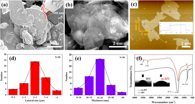
The original BN has chemical stability and large thickness, which limits its dispersibility in the organic matrix and the improvement of the overall TC [53]. To illustrate the successful stripping and modification of BN, the microscopic morphology and element bond analysis were tested by using SEM, AFM and FT-IR, respectively. Figure 1a shows the platelet morphology of the original BN, the uneven lateral size (about 5–10 μm) and the thickness of about 500 nm can be clearly observed. After modified by ball milling with boric acid (BA), the obtained m-BN presents a thin and transparent morphology (Fig. 1b). Taking 50 pieces of m-BN flakes for further observed with an atomic force microscope, from Fig. 1c–e, it is found that the m-BN with an average lateral size of 2–3 μm and a thickness of about 20 nm.
Fig. 1.
Characterizations of original BN and m-BN. a, b are SEM images of pristine BN and m-BN. c AFM image, d diameter length and e thickness distribution of m-BN. f FT-IR analysis of BN and m-BN. Insets are the corresponding contact angle test results
The mechanism of BN modification can be found in FT-IR spectra as shown in Fig. 1f. Except for two characteristic peaks of B-N stretching vibration (1375 cm−1) and B-N-B bending vibration (819 cm−1) about original BN, m-BN exhibits two other different broad absorptions at 3420 and 3230 cm−1, which correspond to the –OH and N–H stretching vibration [54, 55]. The acquisition of hydrophilic groups is due to the high-speed mechanical shearing action that makes the N atoms and B atoms in an active state to react with BA [56]. The increase in hydrophilicity of m-BN is verified by the fact that the contact angle of m-BN is significantly smaller than that of BN in the illustration.
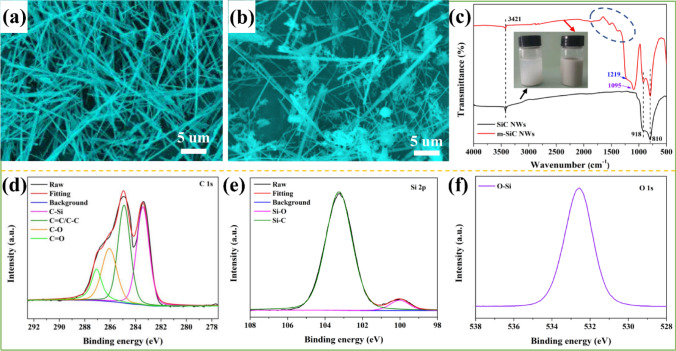
In order to reduce the interface thermal resistance between SiC NWs and BN, SiC NWs are treated by high-temperature oxidation. According to the SEM image in Fig. 2a, the untreated SiC NWS have a rod-like structure with a length of about 25 μm and have a smooth surface without impurities. After calcination at 1300 °C, the surface of the m-SiC NWS becomes rough and has granular aggregates (Fig. 2b). As shown in Fig. 2c, the FT-IR characteristic peaks at around 810 and 918 cm−1 are attributed to the C–Si stretching vibration of SiC NWs [57]. The peak at around 3421 cm−1 belongs to the –OH group in the water absorbed on the surface of the sample. After modification, the new peaks of Si–O–Si and C–O–Si groups at 1095 and 1219 cm−1 appear on m-SiC NWs [58]. Furthermore, a series of peaks located at around of 1500 cm−1 (inside the blue dashed circle) are ascribed to the stretching vibration of C–O and C=O [59].
Fig. 2.
Characterizations of commercial SiC NWS and m-SiC NWS. a, b are SEM images of commercial SiC NWS and m-SiC NWS. c FT-IR spectra of SiC NWS and m-SiC NWS. High-resolution XPS analysis of d C 1s, e Si 2p and f O 1s of m-SiC NWS
Figure 2d–f presents the XPS high-resolution spectra of C, Si and O elements to further confirm the linking of functional groups on m-SiC NWS. From Fig. S1, the C 1s spectrum of commercial SiC NWS shows three fitting peaks at 283.4, 284.9 and 286.4 eV corresponding to C–Si, C=C/C–C and C-O, respectively [60]. While the C 1s spectrum of m-SiC NWS not only contains the above fitting peaks, but also emerges a C=O bond at 287.1 eV. More importantly, after modification, the peak attributed to C=C/C–C gets stronger. In addition, except for the Si–C bond at 102.8 eV in the Si 2p spectrum, an obvious fitting peak found in m-SiC NWS at 100.3 eV corresponds to Si–O bond. [61, 62]. Only one main fitting peak of O 1 s belongs to the O–Si bonding at 532.2 eV. From the above FT-IR and XPS results, it can be inferred that multi-oxygen-containing functional group (Si–O–Si, C–O–Si and C=O) were formed on the surface of m-SiC NWS after calcination treatment [63]. These valence bond structures not only enhance the dispersion of m-SiC NWS in the matrix (from the illustration in Fig. 2c, compared to the commercial SiC NWS, the aqueous dispersion of m-SiC NWS did not show delamination after standing for 24 h), but also provide a theoretical support for m-SiC NWS connecting m-BN to form thermally conductive paths.
Fabrication and Characterization of CA/m-SiC/m-BN and CA/m-SiC/m-BN/EP
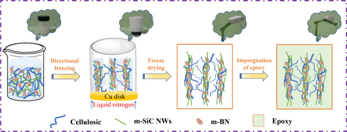
As shown in Fig. 3, the preparation of CA/m-SiC/m-BN/EP can be summarized in the following four processes: firstly, the preparation of a paste dispersion of cellulose/m-SiC/m-BN; then, the mixed dispersion is cross-linked in a mold to form m-SiC/m-BN cellulose hydrogel, which undergoes a directional freezing in a liquid nitrogen environment [64]; Next, the m-SiC/m-BN cellulose hydrogel is freeze-dried to become m-SiC/m-BN cellulose aerogel (CA/m-SiC/m-BN); Finally, CA/m-SiC/m-BN/EP is obtained by impregnating the CA/m-SiC/m-BN aerogel in EP with the aid of a vacuum system. In addition, it can be seen from the vignette that CA/m-SiC/m-BN is lightweight, and even the final CA/m-SiC/m-BN/EP composite can also be placed steadily on the tiny grass branches.
Fig. 3.
Schematic diagram of the preparation of CA/m-SiC/m-BN/EP
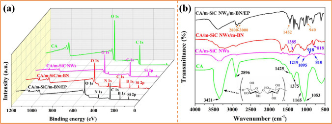
Figure 4 presents the XPS and FT-IR spectra of cellulose aerogel (CA), CA/m-SiC NWS, CA/m-SiC/m-BN and CA/m-SiC/m-BN/EP to further confirm the covalent connection. Specifically, the binding energy peaks of different elements contained in CA, SiC NWS and BN were observed on the hybrid spectrum of CA/m-SiC/m-BN and CA/m-SiC/m-BN/EP (Fig. 4a). As shown in Fig. 4b, the observed peak for pure CA centered at 3421, 1375, 1165 and 1053 cm−1 correspond to the –OH stretching vibration, –OH bending vibration, –CO antisymmetric bridge stretching vibration and –CO–C vibration of pyranoid ring skeleton, respectively [37, 65]. In addition, the bands at 2896 and 1425 cm−1 belong to the absorption peak of the –CH stretching vibration on the pyranoid ring and the branched chains, respectively. After the introduction of m-SiC NWS and m-BN into cellulose, their characteristic peaks successively appeared on the infrared spectra of CA/m-SiC NWS and CA/m-SiC/m-BN, which corresponded to the results in Figs. 1f and 2c. Furthermore, the FT-IR spectrum of the final product CA/m-SiC/m-BN/EP not only contains all the above characteristic peaks, but also adds the obvious absorption peaks of the EP matrix. The bands at 2830–3000, 1452 and 940 cm−1 correspond to the stretching vibration of –CH/–CH2/–CH3, the stretching vibration peak of benzene ring and the characteristic absorption peak of epoxy group (–CH(O)CH–), respectively. It is worth mentioning that the cellulose with polyhydroxy group (inset in Fig. 4b), the m-SiC NWS with multi-oxygen-containing functional group and m-BN with N–H group are tightly combined together relying on the hydrogen bond between these groups. Thus, a stable and continuous thermally conductive structure is formed in CA/m-SiC/m-BN/EP [66].
Fig. 4.
a XPS and b FT-IR spectra of CA, CA/m-SiC NWS, CA/m-SiC NWS/m-BN and CA/m-SiC NWS/m-BN/EP
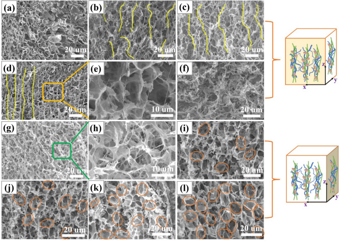
The microstructure of the thermally conductive filler has a significant effect on the TC of the composite. In this work, the microstructure of CA/m-SiC/m-BN is affected by the content of m-SiC NWS and m-BN. From Fig. S2, pure cellulose presents a unique porous network structure with a pore diameter of about 10 μm [67]. The influence of m-SiC NWS on the overall microstructure was studied by changing its content (0.00, 0.03, 0.06, 0.10 and 0.13 g) when the mass of m-BN in the aerogel was controlled at 1.8 g. As shown in Fig. 5a, when m-SiC NWS is not introduced, m-BN in CA/1.8 m-BN is embedded on the hole wall of the CA. With the addition of m-SiC NWS in different masses and assisted by directional freezing, the CA/m-SiC/m-BN skeleton presents a vertically oriented structure in the x–z plane (Fig. 5b–d, f). Especially, when the mass of m-SiC NWS is 0.10 g, CA/0.10 m-SiC/1.8 m-BN shows a high orientation along the ice growth direction. From the enlarged SEM image of Fig. 5e, it can be clearly seen that the m-SiC NWS are arranged in a vertical direction. However, as the mass of SiC NWs continues to increase to 0.13 g, SiC NWs are entangled with each other to limit the vertical growth of ice crystals, resulting in a porous network structure with different pore sizes.
Fig. 5.
SEM images of CA/m-SiC NWS/m-BN with different contents of m-SiC NWS and GO and m-BN. a–d and f are the section morphologies of CA/1.8 m-BN, CA/0.03 m-SiC/1.8 m-BN, CA/0.06 m-SiC/1.8 m-BN, CA/0.10 m-SiC/1.8 m-BN and CA/0.13 m-SiC/1.8 m-BN skeleton in x–z plane. e is local enlarged drawing of d. g, i–l are the section morphologies of CA/0.10 m-SiC, CA/0.10 m-SiC/0.5 m-BN, CA/0.10 m-SiC/1.0 m-BN, CA/0.10 m-SiC/1.5 m-BN and CA/0.10 m-SiC/1.8 m-BN skeleton in x–y plane. h is local enlarged drawing of g
The influence of m-BN on the overall microstructure was studied by changing its content (0.0, 0.5, 1.0, 1.5 and 1.8 g) when the mass of SiC NWs in the aerogel was controlled at 0.10 g. From Fig. 5g–h, CA/0.10 m-SiC shows a network structure of cellulose and m-SiC NWS connected without the participation of m-BN. In order to more intuitively show the influence of different contents of m-BN on the overall morphology, the structural characterizations of CA/m-SiC/m-BN skeleton in the x–y plane are shown in Fig. 5i–l. It can be seen that the embedded m-BN in the cellulose increases with increasing its mass. When the mass of m-BN reaches to 1.8 g, the m-BN starts to connect to each other, which is the best content for the construction of thermal conduction path, because excessive BN will aggregate and then increase the interface thermal resistance. More importantly, combined with Fig. 5d, l, it is easy to observe that m-SiC NWS and m-BN form a continuous thermally conductive network structure on the pore wall of CA, which is conducive to the rapid transfer of phonons between the two fillers.
In order to explore the influence of the microscopic morphology of the composite on the thermally conductive properties, the morphology analysis of the EP-based composites is further carried out. As can be seen from Fig. S3a, the cross-sectional morphology of CA/0.10 m-SiC/EP without m-BN shows a stripe structure with single crack direction and vertical extension, and m-SiC NWS can be evenly distributed in EP, which is attributed to their good interfacial compatibility. Similarly, from Fig. S3b, the cross-sectional morphology of CA/1.8 m-BN/EP without m-SiC NWS shows that m-BN is uniformly distributed in EP. For the CA/0.10 m-SiC/1.8 m-BN/EPblend obtained by simple blending, the cross-sectional appearance has no regular and fixed orientation (Fig. S3c). For the optimal sample CA/0.10 m-SiC/1.8 m-BN/EP, an obvious vertical stratification can be observed (Fig. S3d). These results further confirm the successful acquisition of EP-based composites with a vertically oriented thermally conductive network. In addition, the EP can penetrate into the 3D network since the modification of the fillers enhances the interfacial interaction. Therefore, this well-arranged vertical structure can provide an efficient heat transfer channel in the direction of the through-plane, resulting in excellent anisotropic TC [68].
Anisotropic Thermal Properties of CA/m-SiC/m-BN/EP
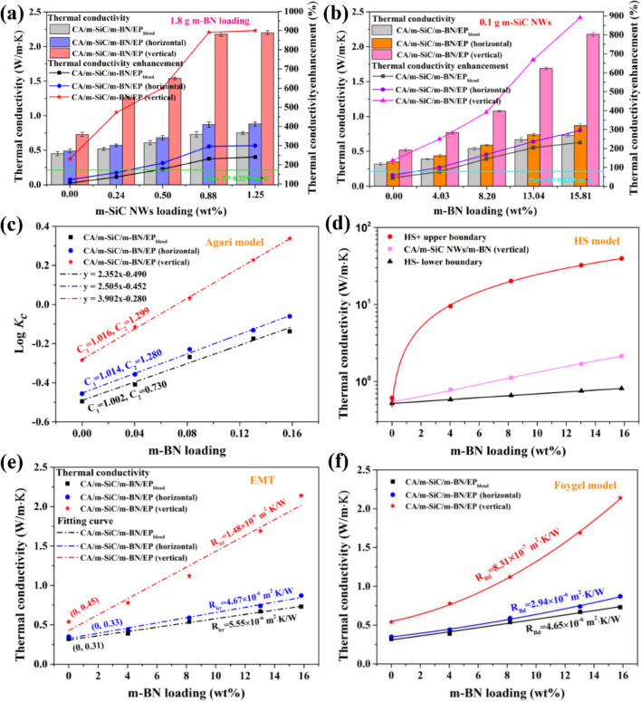
Combined with the thermal gravimetric analyzer, the density and filler loadings of different samples are presented in Tables S1 and S2. Figure 6a, b presents the TC of CA/m-SiC/m-BN/EP composites in both vertical plane and horizontal plane directions with different m-SiC NWS and m-BN contents. It can be seen that the TC of CA/m-SiC/m-BN/EP and CA/m-SiC/m-BN/EPblend composites increased with increasing the content of m-SiC NWS and m-BN, and the existence of the unique thermally conductive network results in a significant enhancement of TC in both directions. For example, whether it is CA/1.8 m-BN/EP and CA/0.10 m-SiC/EP with a single filler, or CA/m-SiC/m-BN/EP with a composite filler, they all perform higher TC than pure EP (0.22 W m−1 K−1) in both vertical plane and horizontal plane. Moreover, at a specific content of m-SiC NWS and m-BN, the TC in both planes for the composite with unique network structure is better than that of the composites with a random dispersion [69]. It is worth noting that in Fig. 6a, the TC of the EP-based composite has basically not changed with the content of m-SiC NWS increased from 0.88 to 1.25 wt% (i.e., 0.10–0.13 g). This is mainly attributed to excessive m-SiC NWS which are entangled with each other (Fig. 5f) and prevent further improvement of TC. In order to visually highlight the superior thermally conductive properties of the composite under the optimal filler content, thermal conductivity enhancement (TCE) was adopted using Eq. (1) [70]:
| 1 |
where Kc and Km are the TC of EP-based composites and pure EP. After calculation, the TCE of the CA/0.10 m-SiC/1.8 m-BN/EP (Kc = 2.21 W m−1 K−1) composite reached 890.9% at the total filler loading of 16.69 wt%, exhibiting excellent TC enhancement performance. In summary, the appropriate contents of m-SiC NWS and m-BN in CA/m-SiC/m-BN/EP are 0.88 wt% (0.10 g) and 15.81 wt% (1.8 g), respectively.
Fig. 6.
Anisotropic thermal properties analysis of CA/m-SiC/m-BN/EP. a Thermal conductivities and thermal conductivity enhancements of CA/m-SiC/m-BN/EP and CA/m-SiC/m-BN/EPblend composites with different m-SiC NWS contents at the m-BN mass of 1.8 g. b Thermal conductivities and thermal conductivity enhancements of CA/m-SiC/m-BN/EP and CA/m-SiC/m-BN/EPblend composites with different m-BN contents at the m-SiC NWS mass of 0.10 g. c Agari model fitting lines, d Hashin–Shtrikman (HS) model fitting lines, e EMT model fitting lines and f Foygel’s theory fitting lines of CA/m-SiC/m-BN/EP and CA/m-SiC/m-BN/EPblend composites
The TC of the EP-based composites is theoretically described by classic Agari and Hashin–Shtrikman (HS) models, which are often used to test the filler distribution in the specific network. In view of the relatively low content of m-SiC NWS (about 0.24–0.88 wt% concluded from Tables S1 and S2) in CA/m-SiC/m-BN/EP, the filler m-BN contributes significantly better to the TC of the composite than m-SiC as shown in Fig. 6a, b. Therefore, in this work, m-SiC/EP is regarded as a matrix and m-BN is used as a thermally conductive filler to simplify the simulation structure. The Agari model is shown as Eq. (2) [71]:
| 2 |
where Kc, Kf and Km represent the TC of EP-based composites, m-BN and matrix (m-SiC/EP), respectively. Here, Kf is 350 W m−1 K−1 in horizontal and 600 W m−1 K−1 in the vertical direction, and 30 W m−1 K−1 in random dispersion. Km is 0.35 W m−1 K−1 in horizontal and 0.52 W m−1 K−1 in the vertical direction, and 0.32 W m−1 K−1 in random dispersion. φ is the weight fraction of m-BN filler. C1 is the influence parameter of filler on the secondary structure of polymer matrix. C2 measures how easily the filler can form a thermally conductive network [72]. From Fig. 6c, compared with CA/m-SiC/m-BN/EPblend through a simple blending (random dispersion) method, CA/m-SiC/m-BN/EP obtained by the ice template method has larger C1 and C2 after simulation calculation on the vertical and horizontal planes. This indicates that an ideal crystal structure and heat conduction paths are formed inside CA/m-SiC/m-BN/EP [73], especially in the vertical direction.
In order to further highlight the unique vertical net structure formed inside CA/m-SiC/m-BN/EP, the Hashin–Shtrikman (HS) model is introduced as Eqs. (3, 4) [74]:
| 3 |
| 4 |
where the KHS+ (upper boundary) refers to the matrix that is completely surrounded by filler; KHS+ (lower boundary) indicates that the fillers are completely separated by matrix. Kf and Km represent the TC of m-BN and matrix (m-SiC/EP), In that case, Kf takes a value of 600 W m−1 K−1 and Km takes a value of 0.52 W m−1 K−1. φm and φf are the weight fraction of matrix and filler. Figure 6d presents the simulation results of anisotropic TC in accordance with HS model. Obviously, the measured TC stays between the upper and lower boundaries, which meets the fitting result of the HS model. The appearance of the approximate logarithmic fitting curve of the HS + upper boundary shows that the construction of the heat conduction paths in this experiment can achieve a greater impact on the overall TC with a low m-BN content.
In practical application, the interfacial thermal resistance between the filler/matrix and filler/filler in the thermally conductive composites is the key factor affecting the heat transfer process [26]. Therefore, the effective medium theory (EMT) and the Foygel theory are used to model and analyze the interfacial thermal resistance in the samples. EMT is used to fit the relationship between the interface thermal resistance from filler/matrix and the TC as shown in Eq. (5) [75]:
| 5 |
where Kc, Kf and Km are the TC of composite, m-BN and matrix (m-SiC/EP), respectively. φf is the weight fraction of m-BN, Ritr is the interfacial thermal resistance at m-BN/matrix interface, L and a are the average diameter length and diameter-thickness ratio of m-BN, respectively. The corresponding fitting results are shown in Fig. 6e and the values of Ritr for CA/m-SiC/m-BN/EP in both vertical and horizontal directions and randomly dispersed CA/m-SiC/m-BN/EPblend composites are 1.48 × 10⁻⁶, 4.67 × 10⁻⁶, and 5.55 × 10⁻⁶ m2 KW−1, respectively. This result clearly proves that the successful modification of m-BN enhanced its interaction with the matrix. In addition, Ritr in vertical direction is lower than horizontal direction, which indicates that m-BN can also be tightly bonded to m-SiC (as the matrix) in the vertical direction.
The Foygel model is applied to simulates and calculate the thermal boundary resistance between fillers, as shown by Eqs. (6, 7) [76]:
| 6 |
| 7 |
where Kc and Km are the TC of composite and matrix, K0 is a pre-exponential factor related to the filler. φf is the weight fraction of m-BN, φc is the critical permeability content of the filler, L is the average diameter length of m-BN, β is related to the conductivity index of the filler, and RBd is the thermal boundary resistance at filler/filler interface. It can be seen from Fig. 6f that the RBd of CA/m-SiC/m-BN/EP in vertical direction is as low as 8.31 × 10⁻⁷ m2·K/W, which is nearly one order of magnitude lower than the results of horizontal direction (2.94 × 10⁻⁶ m2 K W−1) and random distribution (4.65 × 10⁻⁶ m2 K W−1). Furthermore, the appearance of an approximate exponential fitting curve in the vertical direction indicates that m-BN is arranged in an orderly manner and no stacking occurs in this direction. This further confirmed the advantages of CA/m-SiC/m-BN/EP with high-speed heat conduction channel in the vertical direction.
To demonstrate the advantage of CA/m-SiC/m-BN/EP obtained in this work in terms of thermally conductive performance, a comparison with previous similar studies is shown in Table S3. After comprehensive comparison, the CA/m-SiC/m-BN/EP exhibits the excellent TC at low content among the reported bulk composites.
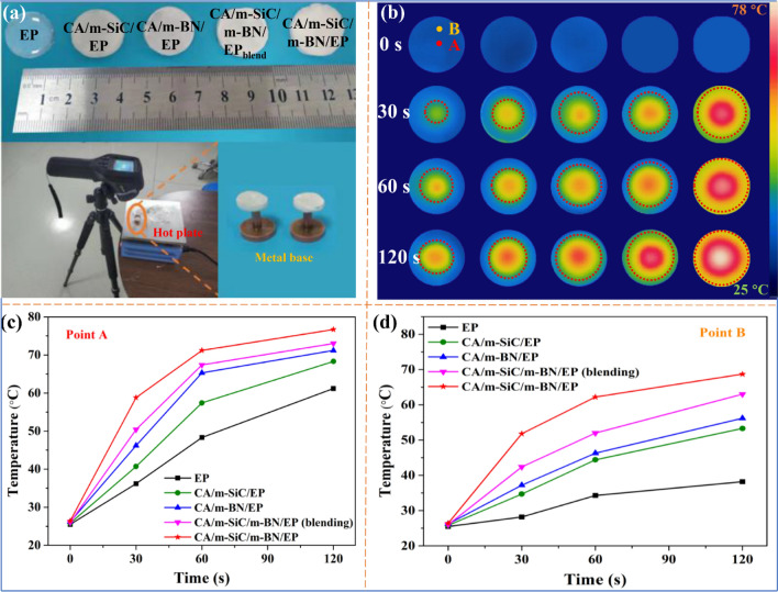
Infrared thermal imager was used to intuitively estimate the thermal management capability of different EP-based composites. Specifically, as shown in Fig. 7a, different samples with a diameter of 2 cm and a thickness of 3 mm are placed simultaneously on a hot plate set at 80 °C, and then, the infrared thermal imager is used to record the surface temperature changes over time. In order to verify that the TC of CA/m-SiC/m-BN/EP is anisotropic in two directions, the custom metal bases are used as the point heat source for the sample in the experimental design. It is worth noting that two test points A and B are selected on the sample surface during the experiment, as shown in Fig. 7b; point A is used to test the temperature change of the sample center with the point heat source in the vertical direction, while point B is used to reflect the thermal conduction capability of the sample in the horizontal direction. It is found that the surface temperature of different samples in the following order: CA/m-SiC/m-BN/EP > CA/m-SiC/m-BN/EPblend > CA/m-BN/EP > CA/m-SiC/EP > EP, this result is consistent with the order of TC obtained in Fig. 6a, b. Obviously, the surface temperature of CA/m-SiC/m-BN/EP at point A shows a fastest increasing with time compared to other samples. The specific temperature change with time of point A recorded by a computer is shown in Fig. 7c. After 120 s, the center temperature of CA/m-SiC/m-BN/EP is as high as 76.7 °C, which is close to the temperature of hot plate. Not only that, as shown in Fig. 7d, the sample CA/m-SiC/m-BN/EP also showed excellent heat transfer efficiency at point B close to the edge (the temperature is about 67.2 °C after 120 s), which shows that CA/m-SiC/m-BN/EP has high thermal conductivity along both vertical and horizontal directions, thereby forming a heat dissipation area with a larger radius [77].
Fig. 7.
a Optical photographs of different EP-based composites and schematic design for thermal imaging test. b Infrared thermal images of different EP-based composites variation with heating time and c–d the temperature changes of A and B on the surface of EP-based composites with heating time
Thermal Conduction Mechanism of Different EP-Based Composites
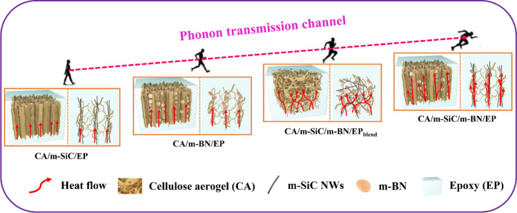
According to the morphology characterization and TC test results of different samples, the heat flow transmission path can be reasonably simulated. In addition, the packaging material is generally coated on the surface of the microelectronic device, so here we focus on the comparison and analysis of the thermally conductive mechanism of different samples in the vertical direction. As we all know, phonons are the collective modulus of the vibrations of mutually coupled atomic lattice systems and are the main thermal energy carriers of polymer-based materials. Therefore, constructing efficient phonon transport channel is the key to improve the TC of thermal interface composites. As shown in Fig. 8, for CA/m-SiC/EP and CA/m-BN/EP with a single filler, the phonon transmission channel mainly relies on the vertically oriented m-SiC NWs and m-BN network structures, respectively. Since the in-plane TC of BN (600 W m−1 K−1)) is higher than the in-line thermal conductivity of m-SiC NWs (100 W m−1 K−1), CA/m-BN/EP exhibits a faster heat flow transfer rate. At the optimal filler content, the TC of CA/m-SiC/m-BN/EPblend with dual fillers randomly dispersed is higher than that of CA/m-BN/EP and CA/m-SiC/EP, which is mainly due to the fact that more phonon transmission paths can be formed inside the structure of CA/m-SiC/m-BN/EPblend [78]. When m-SiC NWs and m-BN form a synergistic vertical network structure in CA/m-SiC/m-BN/EP, resulting in a faster heat flow transfer compared to other samples. Hence, the vertically aligned networks composed of interconnected m-SiC NWs and m-BN heat conductive paths play a critical role in the phonon transmission, which can significantly improve the TC of the composite in the vertical direction [79].
Fig. 8.
Schematic diagram of heat flow of different EP-based composites along the vertical direction
Electrical Insulative Properties of Different EP-Based Composites
Electrical insulation is the basic feature of electronic packaging materials [4]. During the experiment, conductive glue was applied on both sides of the tested sample and the experimental results are shown in Fig. 9. It can be seen that compared with pure EP (8.97 × 10¹⁴ Ω·cm), the resistivity of CA/m-SiC/EP (8.87 × 10⁸ Ω·cm) decreases sharply, while the resistivity of CA/m-BN/EP (9.47 × 10¹⁵ Ω·cm) increases slightly, which is mainly attributed to the linear semiconductor characteristics of m-SiC NWS and the high electrical insulation of BN [80]. For the CA/m-SiC/m-BN/EPblend obtained by random dispersion, there is no consistent linear direction despite the participation of m-SiC NWS, so its resistivity is mainly influenced by EP, which is about 2.42 × 10¹³ Ω·cm. It is worth mentioning that the resistivity of CA/m-SiC/m-BN/EP (2.35 × 10¹¹ Ω·cm) with a vertical network structure decreases compared with that of pure EP and CA/m-SiC/m-BN/EPblend, but it is much higher than the theoretical critical resistivity (1010 Ω·cm) [25], combined with the high resistivity value of CA/m-BN/EP, this is mainly due to the high insulation of m-BN playing an important role in this special structure. It is convinced that the thermal management composite CA/m-SiC/m-BN/EP obtained in this work has a great potential for application in the field of microelectronic packaging.
Fig. 9.
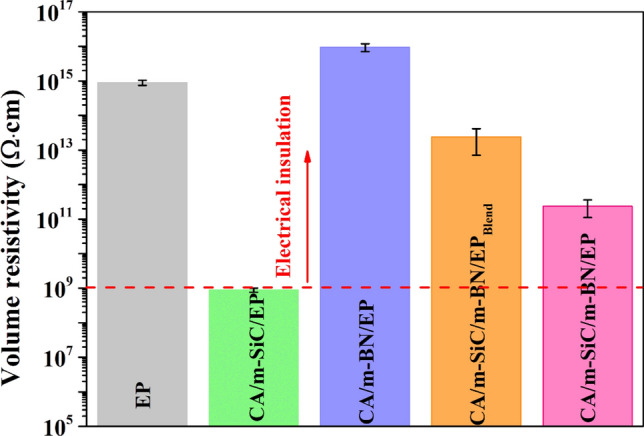
The volume resistivity of pure EP and different EP-based composites in the vertical direction
Dielectric and Electromagnetic Wave Absorption Performances of Different Samples
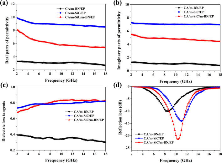
SiC NWs are a very important wide-bandgap semiconductor material and have a high dielectric loss capability, so it shows excellent electromagnetic wave absorption potential [81]. In addition, EP with high resistivity (8.97 × 10¹⁴ Ω·cm) has almost no dielectric response, so the electromagnetic wave absorption capacity of different EP-based composites (CA/m-BN/EP, CA/m-SiC/EP and CA/m-SiC/m-BN/EP) mainly depends on the composition and structural framework of the internal filler. Generally speaking, the electromagnetic wave absorption capacity of non-magnetic dielectric materials is directly determined by the real (ε′) and imaginary (ε″) parts of the complex permittivity, ε′ and ε″ represent the ability to store and dissipate electromagnetic waves, respectively [82, 83]. The obtained ε′, ε″ and the corresponding dielectric loss tangents (tan δε = ε″/ε′) are displayed in Fig. 10a–c. According to dielectric theory, the dielectric loss parameter ε′ for dielectric materials, while ε″ is attributed to the electrical conductivity. And the fast movement of electrons in high-conductivity fillers can also promote polarization. Based on the conductivity of m-SiC is much higher than that of insulating m-BN, therefore, the CA/m-BN/EP exhibits low ε′, ε″, and tanδ values, namely, 2.6–3.3, 0.8–1.3, and 0.3–0.4, respectively. Compared with CA/m-BN/EP, the ε′, ε″, and tan δε values of CA/m-SiC/EP show significant enhancement to 8.5–9.9, 7.0–7.3, and 0.7–0.8, respectively. In addition, tan δε indicates the ability of material to convert electromagnetic waves into other forms of energy (most of which are converted into heat), thereby achieving the dissipation of microwave energy, and a high tan δε value indicates the strong ability to absorb electromagnetic waves [84]. It can be seen from Fig. 10c that CA/m-SiC/m-BN/EP not only has excellent microwave absorption capacity, but also it can convert the absorbed electromagnetic wave energy into heat for effective evacuation through the vertical heat conduction paths according to the aforementioned analysis of thermally conductive properties [85].
Fig. 10.
a Real parts and b imaginary parts of the complex permittivities. c dielectric loss tangents and d reflection loss of the CA/m-SiC/EP, CA/m-BN/EP and CA/m-SiC/m-BN/EP
To evaluate the microwave absorption properties of different composites, the reflection loss (RL) values were calculated according to the transmit line theory by the following Eqs. (8, 9) [86]:
| 8 |
| 9 |
where Zin is the input impedances of the composite, and denote the complex permeability and complex permittivity, respectively, f represents the frequency of microwaves, d refers to the thickness of the composites and c is the velocity of light in vacuum.
Figure 10d shows the electromagnetic wave reflection loss curve of the three systems with a thickness of 3 mm. For the CA/m-SiC/m-BN/EP, the minimum reflection loss is − 21.5 dB at 10.4 GHz, and the effective absorption bandwidth (< − 10 dB) is from 8.8 to 11.6 GHz. According to Maxwell–Wagner polarization theory, this is mainly attributed to the vertical network structure formed by CA/m-SiC/m-BN in composite, which not only strengthens the effective interface (between m-SiC and m-BN) of interfacial polarization, but also enhances the microwave reflection paths [87]. In order to verify the excellent microwave absorption properties of the composites, the impedance matching between the materials and the incident microwaves was further explored. From Fig. S4, compared with CA/m-BN/EP, the microwave impedance of CA/m-SiC/EP and CA/m-SiC/m-BN/EP increases greatly because of their lower complex permittivity. In addition, CA/m-SiC/m-BN/EP exhibits better microwave absorption performance than CA/m-SiC/EP due to higher microwave impedance and almost the same dielectric loss.
Conclusions
In summary, vertically aligned m-SiC NWs/m-BN cellulose aerogel (CA/m-SiC/m-BN) networks have been successfully constructed by ice template combined with directional freezing technology. CA/m-SiC/m-BN/EP composites were prepared by infiltrating the vertical networks with EP. In particular, the high-temperature calcination treatment of SiC NWs and the combined boric acid ball milling modification of BN not only improve the compatibility between the filler and matrix, but also reduce the thermal boundary resistance between the filler and filler, thereby effectively improving the thermal conductivity of the composite material. The CA/m-SiC/m-BN/EP composites exhibit a significantly enhanced TC of 2.21 W m−1 K−1 in vertical plane at a low filler loading of 16.69 wt%, which is increased by 890% compared to pure EP. In addition, from the analysis results of infrared thermal imaging, it is found that CA/m-SiC/m-BN/EP in the horizontal direction also exhibits a better thermally conductive performance than pure EP, CA/m-SiC/EP, CA/m-BN/EP and CA/m-SiC/m-BN/EPblend with random dispersion. Furthermore, CA/m-SiC/m-BN/EP also has a superior volume resistivity of 2.35 × 10¹¹ Ω·cm and a minimum reflection loss of − 21.5 dB. Therefore, the new EP-based composite synthesized in this work will have good application prospects in the fields of electronic packaging.
Supplementary Information
Below is the link to the electronic supplementary material.
Acknowledgements
We acknowledge for the financial support from National Natural Science Foundation of China (21704096, 51703217) and the China Postdoctoral Science Foundation (Grant No. 2019M662526). The authors also gratefully acknowledge financial support from Taif University Researchers Supporting Project Number (TURSP-2020/135), Taif University, Taif, Saudi Arabia.
Funding
Open access funding provided by Shanghai Jiao Tong University.
Contributor Information
Fengmei Su, Email: fmsu@zzu.edu.cn.
Ben Bin Xu, Email: ben.xu@northumbria.ac.uk.
Zhanhu Guo, Email: zguo10@utk.edu, Email: nanomaterials2000@gmail.com.
References
- 1.Lin Y, Kang Q, Wei H, Bao H, Jiang P, et al. Spider web-inspired graphene skeleton-based high thermal conductivity phase change nanocomposites for battery thermal management. Nano-Micro Lett. 2021;13:180. doi: 10.1007/s40820-021-00702-7. [DOI] [PMC free article] [PubMed] [Google Scholar]
- 2.Chen F, Xiao H, Peng ZQ, Zhang ZP, Rong MZ, et al. Thermally conductive glass fiber reinforced epoxy composites with intrinsic self-healing capability. Adv. Compos. Hybrid Mater. 2021;4(4):1048–1058. doi: 10.1007/s42114-021-00303-3. [DOI] [Google Scholar]
- 3.Pan D, Li Q, Zhang W, Dong J, Su F, et al. Highly thermal conductive epoxy nanocomposites filled with 3D BN/C spatial network prepared by salt template assisted method. Compos. Part B. 2021;209:108609. doi: 10.1016/j.compositesb.2021.108609. [DOI] [Google Scholar]
- 4.Zhao Y, Niu M, Yang F, Jia Y, Cheng Y. Ultrafast electro-thermal responsive heating film fabricated from graphene modified conductive materials. Eng. Sci. 2019;8:33–38. doi: 10.30919/es8d501. [DOI] [Google Scholar]
- 5.Aleksandrova M, Jagtap C, Kadam V, Jadkar S, Kolev G, et al. An overview of microelectronic infrared pyroelectric detector. Eng. Sci. 2021;16:82–89. doi: 10.30919/es8d535. [DOI] [Google Scholar]
- 6.Pan D, Su F, Liu C, Guo Z. Research progress for plastic waste management and manufacture of value-added products. Adv. Compos. Hybrid Mater. 2020;3(4):443–461. doi: 10.1007/s42114-020-00190-0. [DOI] [Google Scholar]
- 7.Kong Y, Li Y, Hu G, Cao N, Ling Y, et al. Effects of polystyrene-b-poly(ethylene/propylene)-b-polystyrene compatibilizer on the recycled polypropylene and recycled high-impact polystyrene blends. Polym. Adv. Technol. 2018;29(8):2344–2351. doi: 10.1002/pat.4346. [DOI] [Google Scholar]
- 8.Neto JCM, Nascimento NR, Bello RH, Verçosa LA, Neto JE, et al. Kaolinite review: intercalation and production of polymer nanocomposites. Eng. Sci. 2022;17:28–44. doi: 10.30919/es8d499. [DOI] [Google Scholar]
- 9.Tu J, Li H, Zhang J, Hu D, Cai Z, et al. Latent heat and thermal conductivity enhancements in polyethylene glycol/polyethylene glycol-grafted graphene oxide composites. Adv. Compos. Hybrid Mater. 2019;2(3):471–480. doi: 10.1007/s42114-019-00083-x. [DOI] [Google Scholar]
- 10.Pan D, Su F, Liu H, Liu C, Umar A, et al. Research progress on catalytic pyrolysis and reuse of waste plastics and petroleum sludge. ES Mater. Manuf. 2021;11:3–15. doi: 10.30919/esmm5f415. [DOI] [Google Scholar]
- 11.Hu P, Liu L, Zhao M, Wang J, Ma X, et al. Design, synthesis, and use of high temperature resistant aerogels exceeding 800 °C. ES Mater. Manuf. 2021;15:14–33. doi: 10.30919/esmm5f459. [DOI] [Google Scholar]
- 12.Gu J, Ruan K. Breaking through bottlenecks for thermally conductive polymer composites: a perspective for intrinsic thermal conductivity, interfacial thermal resistance and theoretics. Nano-Micro Lett. 2021;13:110. doi: 10.1007/s40820-021-00640-4. [DOI] [PMC free article] [PubMed] [Google Scholar]
- 13.Atta OM, Manan S, Ul-Islam M, Ahmed AAQ, Ullah MW, et al. Silver decorated bacterial cellulose nanocomposites as antimicrobial food packaging materials. ES Food Agrof. 2021;6:12–26. doi: 10.30919/esfaf590. [DOI] [Google Scholar]
- 14.Yang G, Zhang X, Pan D, Zhang W, Shang Y, et al. Highly thermal conductive poly(vinyl alcohol) composites with oriented hybrid networks: silver nanowire bridged boron nitride nanoplatelets. ACS Appl. Mater. Interfaces. 2021;13(27):32286–32294. doi: 10.1021/acsami.1c08408. [DOI] [PubMed] [Google Scholar]
- 15.Cheng H, Lu Z, Gao Q, Zuo Y, Liu X, et al. PVDF-Ni/PE-CNTs composite foams with co-continuous structure for electromagnetic interference shielding and photo-electro-thermal properties. Eng. Sci. 2021;16:331–340. doi: 10.30919/es8d518. [DOI] [Google Scholar]
- 16.Khan SH, Pathak B, Fulekar MH. A study on the influence of metal (Fe, Bi, and Ag) doping on structural, optical, and antimicrobial activity of ZnO nanostructures. Adv. Compos. Hybrid Mater. 2020;3(4):551–569. doi: 10.1007/s42114-020-00174-0. [DOI] [Google Scholar]
- 17.Chen S, Liu J. Liquid metal enabled unconventional heat and flow transfer. ES Energy Environ. 2019;5:8–21. doi: 10.30919/esee8c318. [DOI] [Google Scholar]
- 18.He X, Ou D, Wu S, Luo Y, Ma Y, et al. A mini review on factors affecting network in thermally enhanced polymer composites: filler content, shape, size, and tailoring methods. Adv. Compos. Hybrid Mater. 2022;5:21–38. doi: 10.1007/s42114-021-00321-1. [DOI] [Google Scholar]
- 19.Pan D, Su F, Liu H, Ma Y, Das R, et al. The properties and preparation methods of different boron nitride nanostructures and applications of related nanocomposites. Chem. Rec. 2020;20(11):1314–1337. doi: 10.1002/tcr.202000079. [DOI] [PubMed] [Google Scholar]
- 20.Deng L, Wang X, Hua X, Lu S, Wang J, et al. Purification of β -SiC powders by heat treatment in vacuum. Adv. Compos. Hybrid Mater. 2020;3(2):177–186. doi: 10.1007/s42114-021-00372-4. [DOI] [Google Scholar]
- 21.Han H, Sun H, Lei F, Huang J, Lyu S, et al. Flexible ethylene-vinyl acetate copolymer/fluorographene composite films with excellent thermal conductive and electrical insulation properties for thermal management. ES Mater. Manuf. 2022;15:53–64. doi: 10.30919/esmm5f523. [DOI] [Google Scholar]
- 22.Hui Y, Xie W, Gu H. Reduced graphene oxide/nanocellulose/amino-multiwalled carbon nanotubes nanocomposite aerogel for excellent oil adsorption. ES Food Agrofor. 2021;5:38–44. doi: 10.30919/esfaf531. [DOI] [Google Scholar]
- 23.Pan D, Zhang X, Yang G, Shang Y, Su F, et al. Thermally conductive anticorrosive epoxy nanocomposites with tannic acid-modified boron nitride nanosheets. Ind. Eng. Chem. Res. 2020;59(46):20371–20381. doi: 10.1021/acs.iecr.0c04510. [DOI] [Google Scholar]
- 24.Yan H, Dai X, Ruan K, Zhang S, Shi X, et al. Flexible thermally conductive and electrically insulating silicone rubber composite films with BNNS@Al2O3 fillers. Adv. Compos. Hybrid Mater. 2021;4(1):36–50. doi: 10.1007/s42114-021-00208-1. [DOI] [Google Scholar]
- 25.Zhou Y, Liu F, Chen CY. Use of BN-coated copper nanowires in nanocomposites with enhanced thermal conductivity and electrical insulation. Adv. Compos. Hybrid Mater. 2019;2(1):46–50. doi: 10.1007/s42114-019-00077-9. [DOI] [Google Scholar]
- 26.Wang S, Lu X, Negi A, He J, Kim K, et al. Revisiting the reduction of thermal conductivity in nano- to micro-grained bismuth telluride: the importance of grain-boundary thermal resistance. Eng. Sci. 2022;17:45–55. doi: 10.30919/es8d513. [DOI] [Google Scholar]
- 27.Feng CP, Bai L, Bao RY, Liu ZY, Yang MB, et al. Electrically insulating POE/BN elastomeric composites with high through-plane thermal conductivity fabricated by two-roll milling and hot compression. Adv. Compos. Hybrid Mater. 2018;1(1):160–167. doi: 10.1007/s42114-017-0013-2. [DOI] [Google Scholar]
- 28.Pan D, Dong J, Yang G, Su F, Chang B, et al. Ice template method assists in obtaining carbonized cellulose/boron nitride aerogel with 3D spatial network structure to enhance the thermal conductivity and flame retardancy of epoxy-based composites. Adv. Compos. Hybrid Mater. 2022;5:58–70. doi: 10.1007/s42114-021-00362-6. [DOI] [Google Scholar]
- 29.Yang G, Zhang X, Shang Y, Xu P, Pan D, et al. Highly thermally conductive polyvinyl alcohol/boron nitride nanocomposites with interconnection oriented boron nitride nanoplatelets. Compos. Sci. Technol. 2021;201:108521. doi: 10.1016/j.compscitech.2020.108521. [DOI] [Google Scholar]
- 30.Wu Y, Xue Y, Qin S, Liu D, Wang X, et al. BN nanosheet/polymer films with highly anisotropic thermal conductivity for thermal management applications. ACS Appl. Mater. Interfaces. 2017;9(49):43163–43170. doi: 10.1021/acsami.7b15264. [DOI] [PubMed] [Google Scholar]
- 31.Xiao C, Guo Y, Tang Y, Ding J, Zhang X, et al. Epoxy composite with significantly improved thermal conductivity by constructing a vertically aligned three-dimensional network of silicon carbide nanowires/ boron nitride nanosheets. Compos. Part B. 2020;187:107855. doi: 10.1016/j.compositesb.2020.107855. [DOI] [Google Scholar]
- 32.Xie Y, Yang Y, Liu Y, Wang S, Guo X, et al. Paraffin/polyethylene/graphite composite phase change materials with enhanced thermal conductivity and leakage-proof. Adv. Compos. Hybrid Mater. 2021;4(3):543–551. doi: 10.1007/s42114-021-00249-6. [DOI] [Google Scholar]
- 33.Sun J, Zhang X, Du Q, Murugadoss V, Wu D, et al. The contribution of conductive network conversion in thermal conductivity enhancement of polymer composite: a theoretical and experimental study. ES Mater. Manuf. 2021;13:53–65. doi: 10.30919/esmm5f450. [DOI] [Google Scholar]
- 34.Chen X, Lim JSK, Yan W, Guo F, Liang YN, et al. Salt template assisted BN scaffold fabrication toward highly thermally conductive epoxy composites. ACS Appl. Mater. Interfaces. 2020;12(14):16987–16996. doi: 10.1021/acsami.0c04882. [DOI] [PubMed] [Google Scholar]
- 35.Zhou W, Zhang Y, Wang J, Li H, Xu W, et al. Lightweight porous polystyrene with high thermal conductivity by constructing 3D interconnected network of boron nitride nanosheets. ACS Appl. Mater. Interfaces. 2020;12(41):46767–46778. doi: 10.1021/acsami.0c11543. [DOI] [PubMed] [Google Scholar]
- 36.Xu F, Bao D, Cui Y, Gao Y, Lin D, et al. Copper nanoparticle-deposited graphite sheets for highly thermally conductive polymer composites with reduced interfacial thermal resistance. Adv. Compos. Hybrid Mater. 2021 doi: 10.1007/s42114-021-00367-1. [DOI] [Google Scholar]
- 37.Song P, Liu B, Liang C, Ruan K, Qiu H, et al. Lightweight, flexible cellulose-derived carbon aerogel@reduced graphene oxide/pdms composites with outstanding EMI shielding performances and excellent thermal conductivities. Nano-Micro Lett. 2021;13:91. doi: 10.1007/s40820-021-00624-4. [DOI] [PMC free article] [PubMed] [Google Scholar]
- 38.Gu H, Gao C, Zhou X, Du A, Naik N, et al. Nanocellulose nanocomposite aerogel towards efficient oil and organic solvent adsorption. Adv. Compos. Hybrid Mater. 2021;4(3):459–468. doi: 10.1007/s42114-021-00289-y. [DOI] [Google Scholar]
- 39.Zhang Y, Luo Y. Naturally derived nanomaterials for multidisciplinary applications and beyond. ES Food Agrof. 2021;4:1–2. doi: 10.30919/esfaf484. [DOI] [Google Scholar]
- 40.Zhuang Z, Wang W, Wei Y, Li T, Ma M, et al. Preparation of polyaniline nanorods/manganese dioxide nanoflowers core/shell nanostructure and investigation of electrochemical performances. Adv. Compos. Hybrid Mater. 2021;4(4):938–945. doi: 10.1007/s42114-021-00225-0. [DOI] [Google Scholar]
- 41.Tong Y, Zhao W, Wu W, Zhang D, He G, et al. Realizing enhanced dielectric and mechanical performance of polyvinylidene fluoride/SiC nanocomposites through a bio-inspired interface design. Adv. Compos. Hybrid Mater. 2022;5(1):263–277. doi: 10.1007/s42114-021-00333-x. [DOI] [Google Scholar]
- 42.Kim K, Ju H, Kim J. Vertical particle alignment of boron nitride and silicon carbide binary filler system for thermal conductivity enhancement. Compos. Sci. Technol. 2016;123:99–105. doi: 10.1016/j.compscitech.2015.12.004. [DOI] [Google Scholar]
- 43.Zhang X. Applications of kinetic methods in thermal analysis: a review. Eng. Sci. 2021;14:1–13. doi: 10.30919/es8d1132. [DOI] [Google Scholar]
- 44.Liang C, Du Y, Wang Y, Ma A, Huang S, et al. Intumescent fire-retardant coatings for ancient wooden architectures with ideal electromagnetic interference shielding. Adv. Compos. Hybrid Mater. 2021;4(4):979–988. doi: 10.1007/s42114-021-00274-5. [DOI] [Google Scholar]
- 45.Zhou Y, Zhang J, Qu C, Li L, Kong J, et al. Synchronously improved wave-transparent performance and mechanical properties of cyanate ester resins via introducing fluorine-containing linear random copolymer. Adv. Compos. Hybrid Mater. 2021;4(4):1166–1175. doi: 10.1007/s42114-021-00349-3. [DOI] [Google Scholar]
- 46.Wang W, Deng X, Liu D, Luo F, Cheng H, et al. Broadband radar-absorbing performance of square-hole structure. Adv. Compos. Hybrid Mater. 2022;5:525–535. doi: 10.1007/s42114-021-00376-0. [DOI] [Google Scholar]
- 47.Luo F, Liu D, Cao T, Cheng H, Kuang J, et al. Study on broadband microwave absorbing performance of gradient porous structure. Adv. Compos. Hybrid Mater. 2021;4(3):591–601. doi: 10.1007/s42114-021-00275-4. [DOI] [Google Scholar]
- 48.Shao W, Liu D, Cao T, Cheng H, Kuang J, et al. Study on favorable comprehensive properties of superhydrophobic coating fabricated by polytetrafluoroethylene doped with graphene. Adv. Compos. Hybrid Mater. 2021;4(3):521–533. doi: 10.1007/s42114-021-00243-y. [DOI] [Google Scholar]
- 49.Budumuru S, Anuradha MS. Electromagnetic shielding and mechanical properties of al6061 metal matrix composite at x-band for oblique incidence. Adv. Compos. Hybrid Mater. 2021;4(4):1113–1121. doi: 10.1007/s42114-021-00338-6. [DOI] [Google Scholar]
- 50.Zhang P, Zhang X, Li B, Xu L, Dang F, et al. Enhanced microwave absorption performance in an ultralight porous single-atom Co–N–C absorber. Adv. Compos. Hybrid Mater. 2021;4(4):1292–1301. doi: 10.1007/s42114-021-00308-y. [DOI] [Google Scholar]
- 51.Zhang J, Lei W, Chen J, Liu D, Tang B, et al. Enhancing the thermal and mechanical properties of polyvinyl alcohol (PVA) with boron nitride nanosheets and cellulose nanocrystals. Polymer. 2018;148:101–108. doi: 10.1016/j.polymer.2018.06.029. [DOI] [Google Scholar]
- 52.Bai T, Guo Y, Liu H, Song G, Zhang D, et al. Achieving enhanced electromagnetic shielding and absorption capacity of cellulose-derived carbon aerogels via tuning the carbonization temperature. J. Mater. Chem. C. 2020;8(15):5191–5201. doi: 10.1039/d0tc00448k. [DOI] [Google Scholar]
- 53.Liu C, Fang Q, Wang D, Yan C, Liu F, et al. Carbon and boron nitride nanotubes: structure, property and fabrication. ES Mater. Manuf. 2019;3:2–15. doi: 10.30919/esmm5f199. [DOI] [Google Scholar]
- 54.Ma Z, Xiang X, Shao L, Zhang Y, Gu J. Multifunctional wearable silver nanowire decorated leather nanocomposites for joule heating, electromagnetic interference shielding and piezoresistive sensing. Angew. Chem. Int. Ed. 2022;61(15):202200705. doi: 10.1002/anie.202200705. [DOI] [PubMed] [Google Scholar]
- 55.Kashfipour MA, Mehra N, Zhu J. A review on the role of interface in mechanical, thermal, and electrical properties of polymer composites. Adv. Compos. Hybrid Mater. 2018;1(3):415–439. doi: 10.1007/s42114-018-0022-9. [DOI] [Google Scholar]
- 56.Yu C, Zhang Q, Zhang J, Geng R, Tian W, et al. One-step in situ ball milling synthesis of polymer-functionalized few-layered boron nitride and its application in high thermally conductive cellulose composites. ACS Appl. Nano Mater. 2018;1(9):4875–4883. doi: 10.1021/acsanm.8b01047. [DOI] [Google Scholar]
- 57.Yan H, Li Q, Wang Z, Wu H, Wu Y, et al. Effect of different sintering additives on the microstructure, phase compositions and mechanical properties of Si3N4/SiC ceramics. ES Mater. Manuf. 2022;15:65–71. doi: 10.30919/esmm5f487. [DOI] [Google Scholar]
- 58.Ishikawa T, Kajii S, Matsunaga K, Hogami T, Kohtoku Y, et al. A tough, thermally conductive silicon carbide composite with high strength up to 1600 degreesc in air. Science. 1998;282(5392):1295–1297. doi: 10.1126/science.282.5392.1295. [DOI] [PubMed] [Google Scholar]
- 59.Zhang X, Dong J, Pan D, Yang G, Su F, et al. Constructing dual thermal conductive networks in electrospun polyimide membranes with highly thermally conductivity but electrical insulation properties. Adv. Compos. Hybrid Mater. 2021;4(4):1102–1112. doi: 10.1007/s42114-021-00335-9. [DOI] [Google Scholar]
- 60.Xie Y, Zhou B, Du A. Slow-sound propagation in aerogel-inspired hybrid structure with backbone and dangling branch. Adv. Comp. Hybrid Mater. 2021;4(2):248–256. doi: 10.1007/s42114-021-00234-z. [DOI] [Google Scholar]
- 61.Li X, Li W, Liu Q, Chen S, Wang L, et al. Robust high-temperature supercapacitors based on sic nanowires. Adv. Funct. Mater. 2021;31(8):2008901. doi: 10.1002/adfm.202008901. [DOI] [Google Scholar]
- 62.Du B, Zhang D, Qian J, Cai M, He C, et al. Multifunctional carbon nanofiber-SiC nanowire aerogel films with superior microwave absorbing performance. Adv. Compos. Hybrid Mater. 2021;4(4):1281–1291. doi: 10.1007/s42114-021-00286-1. [DOI] [Google Scholar]
- 63.Xu J, Cao J, Guo M, Yang S, Yao H, et al. Metamaterial mechanical antenna for very low frequency wireless communication. Adv. Compos. Hybrid Mater. 2021;4(3):761–767. doi: 10.1007/s42114-021-00278-1. [DOI] [Google Scholar]
- 64.Guo Z, Li A, Sun Z, Yan Z, Liu H, et al. Negative permittivity behavior in microwave frequency from cellulose-derived carbon nanofibers. Adv. Compos. Hybrid Mater. 2022;5:50–57. doi: 10.1007/s42114-021-00314-0. [DOI] [Google Scholar]
- 65.Guo DM, An QD, Xiao Z, Zhai SR, Shi Z. Polyethylenimine-functionalized cellulose aerogel beads for efficient dynamic removal of chromium(vi) from aqueous solution. RSC Adv. 2017;7(85):54039–54052. doi: 10.1039/c7ra09940a. [DOI] [Google Scholar]
- 66.He Z, Yang M, Wang L, Bao E, Zhang H. Concentrated photovoltaic thermoelectric hybrid system: an experimental and machine learning study. Eng. Sci. 2021;15:47–56. doi: 10.30919/es8d440. [DOI] [Google Scholar]
- 67.Li Y, Guo J, Li M, Tang Y, Murugadoss V, et al. Recent application of cellulose gel in flexible sensing-a review. ES Food Agrofor. 2021;4:9–27. doi: 10.30919/esfaf466. [DOI] [Google Scholar]
- 68.Kashfipour MA, Mehra N, Dent RS, Zhu J. Regulating intermolecular chain interaction of biopolymer with natural polyol for flexible, optically transparent and thermally conductive hybrids. Eng. Sci. 2019;8:11–18. doi: 10.30919/es8d508. [DOI] [Google Scholar]
- 69.Liu P, Li X, Min P, Chang X, Shu C, et al. 3D lamellar-structured graphene aerogels for thermal interface composites with high through-plane thermal conductivity and fracture toughness. Nano-Micro Lett. 2020;13:22. doi: 10.1007/s40820-020-00548-5. [DOI] [PMC free article] [PubMed] [Google Scholar]
- 70.Chen N, Li T, Wang Y, Pan L, Bao W, et al. Generalized “slope method” of the 3ω analysis to measure the thermal conductivity and heat capacity of solids: frequency- vs. current-sweep. ES Energy Environ. 2020;10:13–21. doi: 10.30919/esee8c725. [DOI] [Google Scholar]
- 71.Yang X, Liang C, Ma T, Guo Y, Kong J, et al. A review on thermally conductive polymeric composites: classification, measurement, model and equations, mechanism and fabrication methods. Adv. Compos. Hybrid Mater. 2018;1(2):207–230. doi: 10.1007/s42114-018-0031-8. [DOI] [Google Scholar]
- 72.Hu X, Wu H, Liu S, Gong S, Du Y, et al. Fabrication of organic shape-stabilized phase change material and its energy storage applications. Eng. Sci. 2022;17:1–27. doi: 10.30919/es8d474. [DOI] [Google Scholar]
- 73.Huang JP. Thermal metamaterials make it possible to control the flow of heat at will. ES Energy Environ. 2019;6:1–3. doi: 10.30919/esee8c368. [DOI] [Google Scholar]
- 74.Fu H, Xiao Y, Li P, Qian W, Li D, et al. Ultrasonic-assisted soldering for graphite films as heat sinks with durably superior heat dissipating efficiency. Adv. Compos. Hybrid Mater. 2021 doi: 10.1007/s42114-021-00255-8. [DOI] [Google Scholar]
- 75.Xue Y, Lofland S, Hu X. Protein-based flexible thermal conductive materials with continuous network structure: Fabrication, properties, and theoretical modeling. Compos. Part B. 2020;201:108377. doi: 10.1016/j.compositesb.2020.108377. [DOI] [Google Scholar]
- 76.Fu C, Yan C, Ren L, Zeng X, Du G, et al. Improving thermal conductivity through welding boron nitride nanosheets onto silver nanowires via silver nanoparticles. Compos. Sci. Technol. 2019;177:118–126. doi: 10.1016/j.compscitech.2019.04.026. [DOI] [Google Scholar]
- 77.Li QY, Hao Q, Zhu T, Zebarjadi M, Zebarjadi M. Nanostructured and heterostructured 2D materials for thermoelectrics. Eng. Sci. 2021;13:24–50. doi: 10.30919/es8d1136. [DOI] [Google Scholar]
- 78.Liu C, Wu C, Lu P, Zhao Y. Non-monotonic thickness dependent hydrodynamic phonon transport in layered titanium trisulphide: first-principles calculation and improved callaway model fitting. ES Energy Environ. 2021;14:34–42. doi: 10.30919/esee8c521. [DOI] [Google Scholar]
- 79.Hao Q, Garg J. A review on phonon transport within polycrystalline materials. ES Mater. Manuf. 2021;14:36–50. doi: 10.30919/esmm5f480. [DOI] [Google Scholar]
- 80.Bhushan RK. Effect of SiC particle size and weight % on mechanical properties of AA7075 sic composite. Adv. Compos. Hybrid Mater. 2021;4(1):74–85. doi: 10.1007/s42114-020-00175-z. [DOI] [Google Scholar]
- 81.Micheli D, Vricella A, Pastore R, Marchetti M. Synthesis and electromagnetic characterization of frequency selective radar absorbing materials using carbon nanopowders. Carbon. 2014;77:756–774. doi: 10.1016/j.carbon.2014.05.080. [DOI] [Google Scholar]
- 82.Asmatulu R, Bollavaram PK, Patlolla VR, Alarifi IM, Khan WS. Investigating the effects of metallic submicron and nanofilms on fiber-reinforced composites for lightning strike protection and emi shielding. Adv. Compos. Hybrid Mater. 2020;3(1):66–83. doi: 10.1007/s42114-020-00135-7. [DOI] [Google Scholar]
- 83.Xie P, Liu Y, Feng M, Niu M, Liu C, et al. Hierarchically porous Co/C nanocomposites for ultralight high-performance microwave absorption. Adv. Compos. Hybrid Mater. 2021;4(1):173–185. doi: 10.1007/s42114-020-00202-z. [DOI] [Google Scholar]
- 84.Gao Q, Pan Y, Zheng G, Liu C, Shen C, et al. Flexible multilayered MXene/thermoplastic polyurethane films with excellent electromagnetic interference shielding, thermal conductivity, and management performances. Adv. Compos. Hybrid Mater. 2021;4(2):274–285. doi: 10.1007/s42114-021-00221-4. [DOI] [Google Scholar]
- 85.Han Y, Ruan K, Gu J. Janus (BNNS/ANF)-(AgNWs/ANF) thermal conductivity composite films with superior electromagnetic interference shielding and joule heating performances. Nano Res. 2022 doi: 10.1007/s12274-022-4159-z. [DOI] [Google Scholar]
- 86.Dilli R, Chandra R, Jordhana D. Ultra-massive MIMO technologies for 6G wireless networks. Eng. Sci. 2021;16:308–318. doi: 10.30919/es8d571. [DOI] [Google Scholar]
- 87.Song P, Ma Z, Qiu H, Ru Y, Gu J. High-efficiency electromagnetic interference shielding of rGO@ FeNi/epoxy composites with regular honeycomb structures. Nano-Micro Lett. 2022;14:51. doi: 10.1007/s40820-022-00798-5. [DOI] [PMC free article] [PubMed] [Google Scholar]
Associated Data
This section collects any data citations, data availability statements, or supplementary materials included in this article.


