Abstract
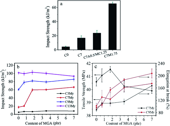
Vibro-milling, a solid-phase mechanochemistry method, was used to prepare an amphiphilic composite particle, which is referred to as MGA. The Molau test, Fourier-transform infrared spectroscopy (FTIR), and differential scanning calorimetry (DSC) results indicated that the core–shell structure of the acrylic impact modifier, acrylate core–shell rubber (ACR), was destroyed after vibro-milling. The ACR core was exposed and reacted with polyvinyl chloride (PVC) chains. Using 1.75 parts per hundred rubber (phr) MGA instead of 1.25 phr MC and 0.5 phr ACR, a significant enhancement effect was achieved. The notched impact strength of the PVC composites increased from 4.24 kJ m−2 for neat PVC and 23.79 kJ m−2 for C7A0.5MC1.25 to 65.5 kJ m−2 for C7M1.75. Additionally, the tensile strength and elongation at break of the PVC composites were enhanced. Studies using a variety of characterization techniques show that the addition of MGA can promote the formation of an intermingled and riveted structure, and thus increase interfacial interactions and the effects of stress transfer, releasing the planar strain. The introduction of MGA can also induce the chlorinated polyethylene (CPE) phase to form a network structure at a lower CPE content, which contributes to networking and crazing and is the main toughening mechanism.
Vibro-milling, a solid-phase mechanochemistry method, was used to prepare an amphiphilic composite particle, which is referred to as MGA.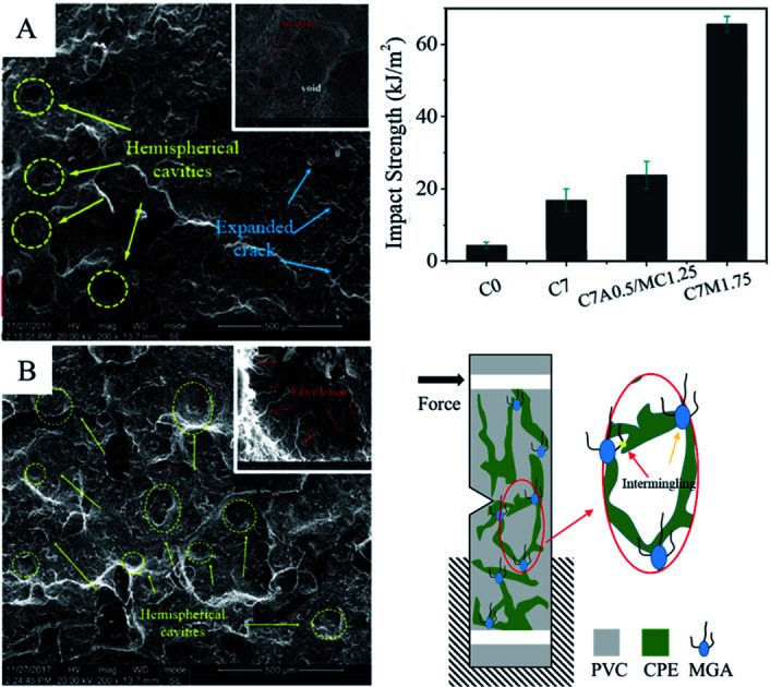
1. Introduction
Polyvinyl chloride (PVC), a typical polymer material with a multi-layered pomegranate-like structure, was first industrialized in the 1930s. It was the second most widely produced material in 2003 with a production capacity of about 33 860 kt, which increased to 56 000 kt in 2019. Its consumption has increased from 18 000 kt in 2003 to 46 280 kt in 2019, making it the most commonly used general plastic. Rigid PVC accounts for over 60% of this total. However, PVC is a typical brittle thermoplastic. Its impact strength is only 3–5 kJ m−2, which is far from that required for many uses. Therefore, PVC toughening is essential.
From 1980 to 2018, hundreds of works related to improving the impact strength of PVC were published, over 90% of which used traditional rigid particles and rubber as toughening agents. Rigid particles, such as calcium carbonate (CaCO3),1,2 silica (SiO2),3,4 and organic halloysite nanotubes,5 among others, can both toughen and strengthen PVC, but the improvement is limited. A significant improvement in toughness can be obtained with the addition of elastomers, such as chlorinated polyethylene (CPE),6,7 acrylonitrile–butadiene rubber (NBR),8 methyl-methacrylate–butadiene–styrene (MBS),9 and acrylate core–shell rubber (ACR), among others. The core of ACR is butyl acrylate, which plays a toughening role, and the shell is mainly composed of poly(methyl methacrylate) PMMA, which has good compatibility with PVC.10–12 Among the elastomers, CPE has most commonly been used in industrial PVC products. It is obtained by the chlorination of HDPE13 and shows good flexibility due to the elimination of crystallinity. Furthermore, the good interaction between the highly chlorinated segments of CPE and PVC chains has led to its wide usage in PVC production implementation.
However, at least 10% (by mass) of CPE is needed to form a network structure and thus provide a good improvement in toughness.14,16 However, a high loading of CPE will also inevitably reduce the strength and modulus of PVC products. A great deal of related work has been done to solve this problem. Eastwood et al.15 prepared a series of blocky-CPE (b-CPE) materials with varying chlorine loadings and molecular weights using a suspension chlorination process to improve the compatibility between PVC and polyolefin elastomers (POE) and thus improve the toughening effect. The grafting of CPE is also a very efficient way to improve its compatibility with PVC. For example, Zhang et al.17 prepared CPE grafted with hydroxyl ethyl acrylate (CPE-g-HEA), which shows better miscibility with PVC. Network yielding and crazing yielding are the main reasons for the better toughening effect, which is different from that for traditional CPE. Because of the complexity of the grafting process, more publications have focused on the introduction of a third phase. Polymers such as ultrafine particles of polystyrene (UPS)18,19 and styrene-co-acrylonitrile resin (SAN)13 can not only act as grid points for the CPE phase to promote a perfect network structure, but also improve the plasticity of PVC. Zhang et al.7 introduced ASA, which could selectively disperse into the CPE phase, improving its melt elasticity and leading to a four-fold increase in impact strength. Their research indicated that the synergistic toughening effect could be attributed mainly to the effective transfer of stress. Although many investigations have been carried out, further improvement is desired in light of the large number of applications and increasing demand for special uses.
In this work, an amphiphilic composite particle in a PVC/CPE system, referred to as MGA, was prepared using a solid-phase mechanochemical method. Poly(butyl acrylate) PBA was exposed as a result of the destruction of the core–shell structure of ACR during the vibro-milling process, which terminated the PVC macro-radicals to form the MGA. The “CPE-friendly end” of MGA can be selectively dispersed in the CPE phase, thus promoting the dispersion of CPE in the network structure, while the “PVC-friendly end” of MGA can be dispersed in the PVC phase and at the boundary between the two phases, which can effectively improve the interfacial interaction between PVC and CPE. In PVC/CPE composites with a lower CPE content, the morphology of CPE evolved into a perfect network structure with the addition of MGA. Consequently, the notched impact strength of PVC/CPE composite increased significantly. Additionally, the tensile strength, elongation at break, and fracture toughness of the PVC/CPE/MGA composites were enhanced compared with those of the PVC/CPE composites.
2. Experimental section
2.1. Materials
PVC (SG-5, k = 66–68) was supplied by Sichuan Jinlu Group Co., Ltd, China, and was mixed with 4.2 parts per hundred rubber (phr) of a lead salt complex stabilizer and 0.8 phr polyethylene (PE)-wax before use. The lead salt complex stabilizer and PE-wax were commercial products. ACR (KM355P) was supplied by Rohm and Hass Company (China). CPE (135A) was supplied by Weifang Yaxing Chemical Co., Ltd. These materials were used directly without further purification.
2.2. Sample preparation
In this study, three types of particles were designed and prepared using a solid mechanochemical method (vibro-milling). The sample codes and the treatment modes are listed in Table 1. For all treatment modes, the rotation speed of the vibro-milling was 800 rpm, the steel ball/(PVC + ACR) ratio (by mass) was about 13 : 1, the diameter of the steel balls was between 4 and 12 mm, and the reaction temperature was below 50 °C.
Treatment modes of the different samples.
| Sample code | PVC | ACR | Treatment mode |
|---|---|---|---|
| MC | 100 | 0 | Vibro-milling PVC for 3 h |
| MA | 0 | 100 | Vibro-milling ACR for 1 h |
| MGA-X | 100 | X(=20, 40, 60) | Pre-vibro-milling of PVC for 2 h, followed by adding ACR and the co-vibro-milling of PVC/ACR for 1 h |
The formulae of PVC/CPE composites are listed in Table 2. They were mixed and then melt-blended for 8 min in a two-roll mixer at 180 °C, followed by compression-molding at 185 °C for 5 min, and finally cooling to room temperature under pressure. The specimens for mechanical properties testing were cut from the molded sheets.
Formulae of the different PVC/CPE composites.
| PVC | Stabilizer complex | PE-wax | MC | CPE | ACR | MGA-40 | |
|---|---|---|---|---|---|---|---|
| C0 | 100 | 4.2 | 0.8 | 1.25 | |||
| Cx | 100 | 4.2 | 0.8 | 1.25 | X | ||
| C7A0.5MC1.25 | 100 | 4.2 | 0.8 | 1.25 | 7 | 0.5 | |
| CxMy | 100 | 4.2 | 0.8 | x(=3, 7, 9, 13) | y(=0, 1.75, 3.5, 7) |
2.3. Characterization
2.3.1. Structure of MGA
A Molau test was carried out to compare the core–shell structure of ACR before and after the ball milling process. About 0.5 g MA and ACR were added to 50 ml tetrahydrofuran (THF), respectively. Magnetic stirring was applied at 30 °C to make a homogeneous system. Photographs of the two samples were obtained after the stirring was stopped. Fourier transform infrared spectroscopy (FTIR) measurements were conducted using a Nicolet iS50 FTIR spectrometer (Thermo Sci. Inc., USA) to probe the grafting reactions between PVC and ACR. The transmission mode was used in the wavelength region from 4000 to 550 cm−1. MGA was separated at 80 °C for 24 h using tetrahydrofuran (THF) as the solvent, and a film coating method was used to obtain a thin sheet (about 60 μm). Samples of pure ACR were ground with potassium bromide and pressed into a film with a powder compressing machine. The glass transition behavior of the samples was measured under a nitrogen atmosphere using a differential scanning calorimetry (DSC) instrument (Q20, TA Instruments) to analyze the grafting position of PVC. Samples including CPE/MA (ACR after ball-milling) and CPE/ACR were prepared by simple blending at 180 °C. About 8 mg of the samples were heated from −100 °C to 140 °C at a heating rate of 10 °C min−1. Gel permeation chromatography (GPC) was used to verify the chain breakage behavior of PVC under stress. The HLC-8320GPC instrument (Toko Co., Ltd., Japan) was composed of two chromatographic columns, a TSK gel super HZM-M 6.0* 150 mm and a TSK gel SuperHZ3000 6.0* 150 mm in series, and the differential refractive detector was used. THF was used to dissolve the PVC completely; the flow rate was 0.6 ml min−1, and the temperature was 40 °C. Polystyrene standards were used for the Mw calibration.
2.3.2. Mechanical properties of PVC composites
Tensile tests using dumbbell-shaped samples were conducted at room temperature on a tensile testing machine (Instron 4302) according to GB/T1040-06. The crosshead speed was 50 mm min−1. Notched Izod impact tests were performed using an XJU-22 Cantilever Impact tester according to GB/1843-07 to evaluate the toughness of the PVC composites. Before the impact test, a single-edge V-shaped notch with a depth of 2 mm was milled in all the rectangular bulk specimens (80 × 10 × 4 mm3). All mechanical property data with a standard deviation is an average value of at least seven replicated specimens.
2.3.3. Morphology of PVC composites
Dynamic mechanical analysis (DMA) was carried out using a TA Q800 (TA Instrument) in double cantilever mode to analyze the interfacial interactions between PVC and CPE with and without MGA. Dynamic loss (tan δ) was determined at a frequency of 1 Hz and a heating rate of 3 °C min−1 as a function of the temperature from −50 °C to 140 °C.
2.3.4. Scanning electron microscopy (SEM)
The morphology of the fracture surface was observed using scanning electron microscopy (SEM, JSM-5900LV) at a voltage of 20.0 kV. For phase structure observation, the impact samples were brittlely fractured at liquid nitrogen temperature and then examined using the JSM-5900LV-SEM. All the samples were covered with a thin layer of gold before observation. The morphologies of CPE in the PVC composites were revealed using transmission electron microscopy (TEM). The samples, which had a thickness of about 20 μm, were first dipped in chlorosulfonic acid at −5 °C for 48 h, followed by washing with water at 0 °C and 60 °C for 12 h, respectively. Finally, they were encased in epoxy resin at 50 °C for 3 d. Ultrathin slices of the encased specimens were obtained through cryo-ultramicrotomy using a diamond knife (Leica EM FC6, Germany) at −80 °C. A field-emission gun, energy-filtering TEM (FEI Tecnai G2 F20, USA) operated at 75 kV was utilized to record images of the specimens after 30 min of staining with osmium tetroxide (OsO4).
2.3.5. Rheological properties
The rheological properties of MA/CPE blends were measured using a strain-controlled dynamic rheometer (Bohlin Gemini 2000, Malvern, Great Britain) with a parallel plate geometry (diameter: 25 mm). The strain amplitude was controlled in the linear viscoelastic region and the frequency sweep was performed in the range of 0.1–100 rpm. All measurements were carried out at 180 °C.
3. Results and discussion
3.1. Characterization of MGA
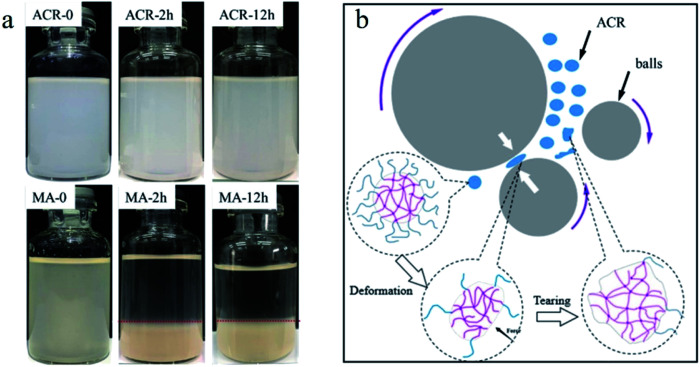
To verify the changes in the core–shell structure of ACR during the vibro-milling process, a Molau test was carried out with tetrahydrofuran (THF) as the solvent, which is a good solvent for the PMMA shell but a poor one for the linked-PBA core. The results are shown in Fig. 1a. The ACR was uniformly dispersed in THF without precipitation after being left alone for 12 h. MA (ACR after ball-milling) was dispersed in THF in the form of a suspension, but aggregation and precipitation occurred after being left alone for 2 h, and it was deposited after 12 h. The shell of ACR is PMMA, which can dissolve well in THF. PMMA acts as an emulsifier to reduce the interfacial tension and increase the dispersion stability. However, the mechanical stress generated by the collision of the high-speed steel balls can break the crisp shell (PMMA). The ACR particles were deformed and torn, resulting in the exposure of the core layer (PBA). Without the emulsification effect of PMMA, the high interfacial tension drives the particles to coalesce and precipitate.
Fig. 1. Digital photographs of pure ACR and MA during the Molau test (a), and a diagrammatic figure of ACR during the vibro-milling process (b).
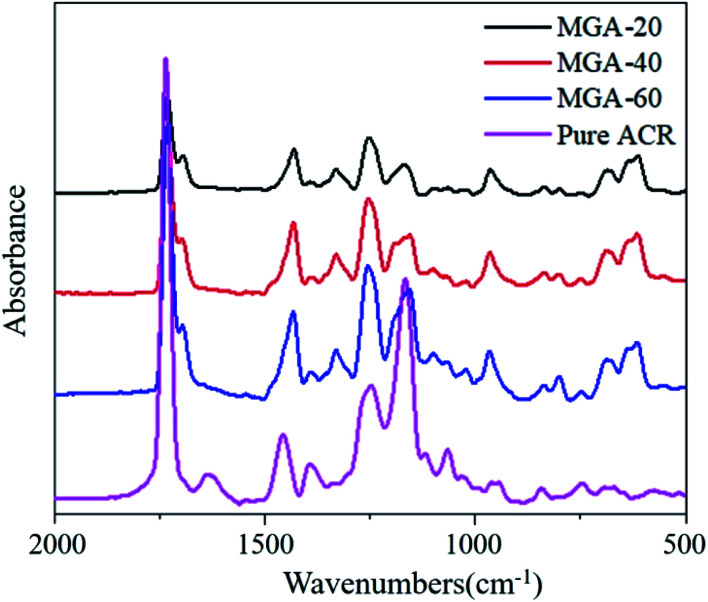
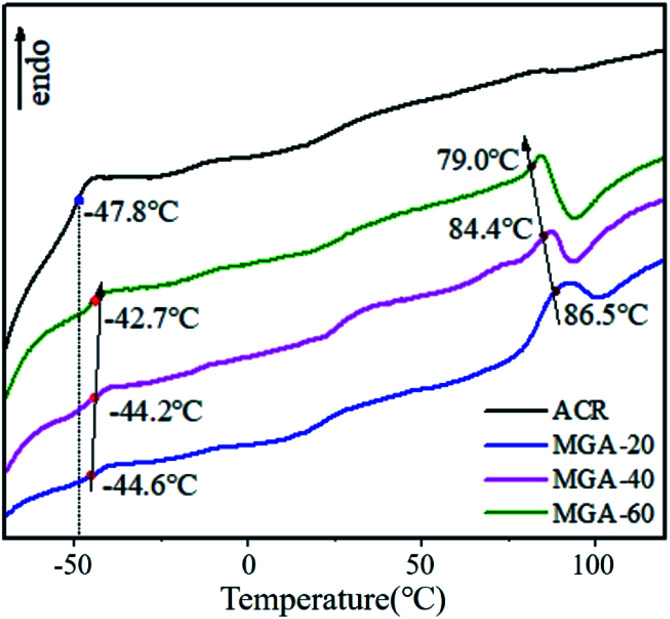
The imposition of a critical stress on a polymer chain can cause the rupture of the chain bonds to form macro-radicals. Xu and Guo20 verified that vibro-milling can cause a reduction of the molecular weight of PVC, the destruction of PVC crystallites, and changes in the PVC morphologic structure. Xiong also verified that mechanochemical reaction is an effective way to prepare a grafting-copolymer.21 Accordingly, in this work, after PVC was pre-milled for 2 h, ACR was added. The PVC and ACR were then co-milled for 1 h, and the obtained sample was referred to as MGA. To investigate the chemical reactions between PVC and ACR, the FTIR spectra of pure ACR and MGA were obtained. Before the test, the MGA was purified using tetrahydrofuran (THF). The FTIR spectra are shown in Fig. 2. An obvious absorption band at 1643 cm−1 corresponding to the stretching vibration of C C appears in the spectrum of pure ACR, but not in that of MGA. Additionally, two absorption bands at 614 cm−1 and 680 cm−1, which were assigned to the stretching vibration of C–Cl, appear in the spectrum of purified MGA. Additionally, ACR is a complex core–shell copolymer of acrylic ester, and the glass transition temperatures (Tg) of the different components can be obtained using thermal analysis. The DSC results for pure ACR and MGA are shown in Fig. 3; their Tg were also calculated. The Tg of poly-butyl acrylate (PBA) was −47.8 °C in pure ACR. It increased to −44.6 °C after vibro-milling with PVC, and further increased with the PVC/ACR ratio. That is, the PBA chain segment of the ACR molecule was restricted and required higher thermal energy to move after the vibro-milling process. Additionally, the Tg of MC was 87.3 °C, while the Tg of PVC in MGA decreased to 86.5 °C and was further reduced with increasing ACR content. All these results indicated that the PVC molecular chain was grafted to the PBA chain segment of ACR.
Fig. 2. FT-IR spectra of the different MGA and ACR samples.
Fig. 3. Differential scanning calorimetry analysis of pure ACR and MGA samples.
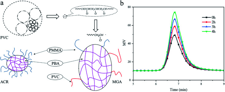
Based on the above analysis, it can be inferred that the chemical reaction during the ball milling process occurs as shown in Fig. 4a. In the vibro-milling process, the collision of high-speed steel balls generates comprehensive stress, including shear, impact, milling, and tearing. The multi-layered pomegranate structure of PVC was broken into primary particles, and the PVC chain was ruptured and formed macro-radicals.20 To verify this behavior, the GPC of PVC vibro-milled for different times was tested. The results in Fig. 4b show that the molecular chain of PVC breaks and the molecular weight decreases under the stress, and free radicals are generated, which verifies some of the conjectures in Fig. 4a. Subsequently, the destruction of the shell of ACR results in the exposure of the nuclear layer. Thus, PVC radicals were terminated by the high-energy surfaces of ACR generated via mechanical activation. That is, the PVC molecular chains were grafted with the PBA chain segment of the ACR.
Fig. 4. (a) A schematic diagram of the chemical reaction during the vibro-milling process; (b) GPC spectra of PVC materials obtained using different vibro-milling times.
3.2. Mechanical properties of PVC/CPE composites
Notched impact strength testing is effective for evaluating the notched toughness of PVC. Fig. 5a shows the notched impact strength of pure PVC (C0) and the C7, C7A0.5MC1.25, and C7M1.75 composites. After adding 7 phr CPE, the impact strength increased from 4.24 kJ m−2 (C0) to 17.76 kJ m−2, and remained almost unchanged after adding 0.5 phr ACR. However, when 1.75 phr MGA was used instead of 1.25 phr MC and 0.5 phr ACR, there was a dramatic increase in the impact strength to 65.5 kJ m−2. Fleischer14 reported that CPE does not have a good toughening effect for PVC unless a network structure is achieved. Fig. 5b shows the notched impact strength of the CxMy composites. There was only a small increase in the notch impact strength for the C3My composites, because MGA cannot promote a network structure when the CPE loading is too low. A network structure was formed when the CPE loading was 13 phr, which resulted in only a slight change in the notched impact strength of the C13My composites. However, there was a dramatic increase in the impact strength of the C7My and C9My composites. This indicates that MGA can promote the formation of a network structure at a lower content of CPE.
Fig. 5. (a) A comparison of the toughening efficiency of CPE with and without MGA. (b) The notched impact strength of CxMy. (c) Tensile strength and elongation at break values of the C7My and C9My composites.
As shown in Fig. 5c, MGA not only improves the toughness of PVC at a low CPE content, but also has a positive effect on its tensile strength and elongation at break.
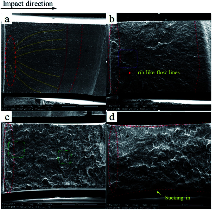
To better investigate the fracture mechanism, the fracture surface of the notched Izod impact test is shown in Fig. 6. The fracture surface of pure PVC is rather smooth with a small amount of parabolic cracks, which are shown as yellow lines in Fig. 6a, and becomes rougher with some rib-like flow lines in C7, as shown in Fig. 6b; this result is in keeping with the higher notched impact strength. Even so, the fracture surface is still a brittle section. In the case of C7M1.75, a prominent brittle–ductile transition occurs with yielding being observed over the entire section, as shown in Fig. 6c. The super-tough fracture properties are consistent with the results of the impact test. Also, in Fig. 6d, which depicts the fracture surface of C7M3.5, some sucking-in of the side occurred, which indicates that the plane strain was consumed by the soft elastomer.22,23
Fig. 6. SEM images of the impacted fracture surfaces of pure PVC (a), C7 (b), C7M1.75 (c), and C7M3.5 (d).
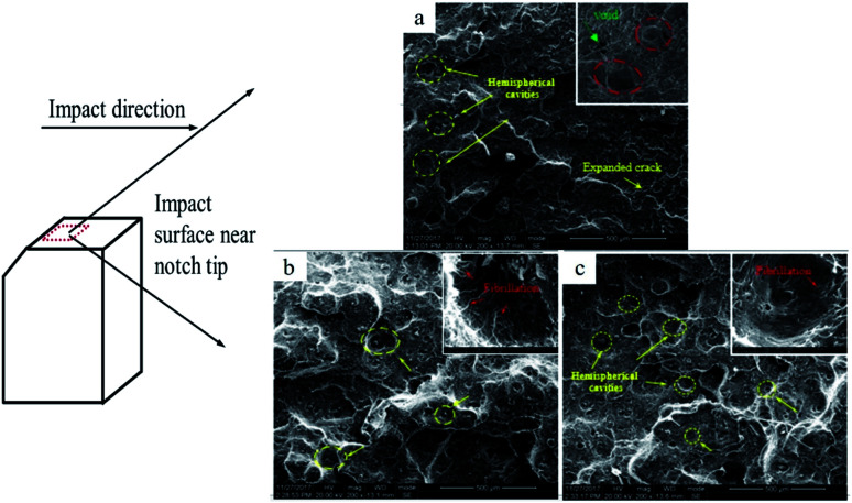
Fig. 7 shows the impacted fracture surface of C7Mx near the notch at higher magnification. In the section of the C7 composite, there is a small shear yield zone close to the notch, which is shown with a yellow arrow in Fig. 7a, and a mass of cracks. The former is cold-drawn and formed under the high-speed impact, and the latter is expanded by the inactivation of the crazing. Fig. 7b and c are the impact fracture surfaces of the C7M1.75 and C7M3.5 composites. After adding 1.75 phr MGA, a brittle–ductile transition occurs. The section is completely yielding with a large amount of fibrillation distributed in hemispherical cavities, as shown by the red arrows in Fig. 7b. The fibrillation results from enhanced interface interaction and can undoubtedly dissipate more energy. The same phenomenon can also be found in Fig. 7c, which shows a clear distinction in the fracture mechanisms of PVC/CPE composites with and without MGA.
Fig. 7. SEM images of the impacted fracture surfaces of (a) C7, (b) C7M1.75, and (c) C7M3.5.
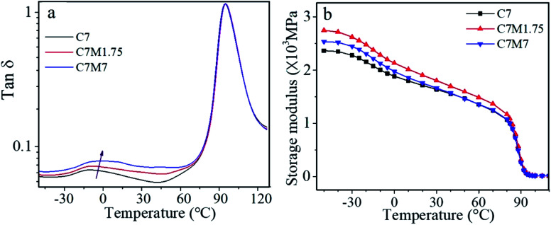
Dynamic mechanical analysis (DMA) is a characteristic method for understanding the structure–performance relationship. As shown in Fig. 8, the loss peak area of the CPE phase increased with increasing MGA content, and the interfacial friction increased. The storage modulus versus temperature curves in Fig. 8b demonstrate that the introduction of MGA improves the storage modulus of the C7 blend, meaning that the rigidity of the blend increases, which corresponds to the tensile strength of the PVC composites. Simultaneously, the modulus of energy storage decreases slightly with increasing the amount of the modifier MGA, which is mainly due to the increase of the butyl acrylate elastomer in ACR.
Fig. 8. Dynamic mechanical properties of the C7My composites: (a) tanδ and (b) storage modulus.
Table 3 shows the Tg of the CPE phases in the PVC composites, which were calculated from the temperature at the loss peak. It was found that the Tg of the CPE phase increases with increasing CPE content in the Cx composites. However, as the MGA content was increased, the Tg of CPE continuously decreased, indicating increased molecular chain activity in C7My. The changes in Tg indicate that part of the butyl acrylate elastomer in MGA was selectively dispersed in CPE.
T g values of CxMy samples calculated from DMA tests.
| Sample | T g |
|---|---|
| C7 | −10.39 |
| C9 | −9.62 |
| C13 | −8.74 |
| C7M1.75 | −7.92 |
| C7M3.5 | −8.67 |
| C7M7 | −10.83 |
3.3. Phase morphology and evolution of the CPE phase
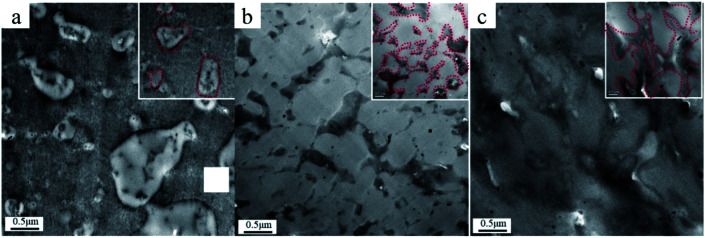
The phase morphologies of the C7, C13, and C7M1.75 composites were observed using TEM. The results are shown in Fig. 9, in which the boundaries of the CPE phases are indicated with dashed red lines. The sea–land structure of the CPE dispersed in PVC when the CPE content is low is shown in Fig. 9a. The sea–land structure evolved into a pseudo-network when the CPE content was increased from 7 phr to 13 phr, accompanied by some land structure (Fig. 9b). When 1.75 phr MGA was introduced in the C7 composite, a total network structure was formed, as shown in Fig. 9c. The TEM results indicate that the introduction of MGA significantly reduced the critical content of CPE required to form a network structure. The transformation of the island structure to the network structure has a significant effect on the mechanical properties of the composites.
Fig. 9. TEM micrographs of PVC/CPE composites ((a): C7; (b): C13; (c): C7M1.75).
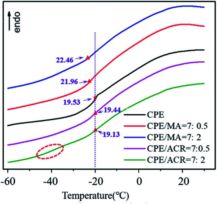
To study the dispersion of MGA in the PVC/CPE composites, MA was prepared to avoid the influence of PVC. The DSC curves of CPE/MA and CPE/ACR are shown in Fig. 10. Because of the poor compatibility between ACR and CPE, the Tg of CPE did not change obviously with increasing ACR content. When MA was introduced in CPE, an obvious decrease in the Tg of CPE was observed, and the Tg continued to decrease with increasing MA content. In particular, at CPE/ACR = 7 : 2, an obvious glass transition stage at about −37.8 °C appears for the CPE/ACR composites, but not for the CPE/MA composites. This indicates that the core–shell structure of ACR was destroyed and the core layer PBA was exposed after vibro-milling, which increased the compatibility of CPE and ACR.
Fig. 10. DSC curves of the CPE/ACR and CPE/MA blends.
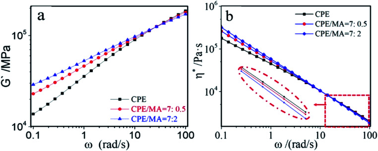
The dynamic rheological properties of the CPE/MA composites are shown in Fig. 11. The storage modulus (G′) of CPE increased when MA was introduced, which indicated that MA can improve the melt elasticity of CPE. The studies of Favis and Chalifoux24 showed that a phase with a higher melt elasticity tended to encapsulate a phase with a lower one, and that it was easier to form a continuous phase. During the plasticization process, the linear CPE melts tended to encapsulate the PVC primary particles and form continuous lamella. The higher melt elasticity of CPE with MGA could prevent the formation of large numbers of holes in the lamella of CPE during the gelation process of the PVC primary particles. Additionally, the higher viscosity at low frequency shown in Fig. 11b indicates that it was difficult for the CPE phase to deform, which could slow the coarsening of CPE during the thermal forming process.
Fig. 11. Dynamic rheological properties of CPE/MA blends: (a) G′; (b) η*.
3.4. Toughening mechanism
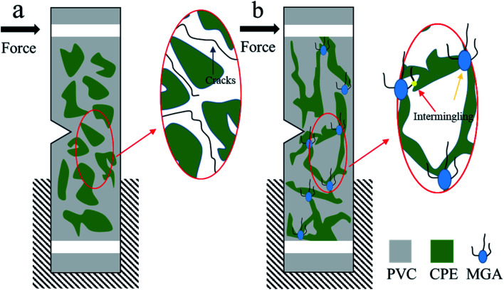
Fig. 12a shows the toughening mechanism of CPE when the CPE loading is low (such as 7 phr). At this loading, CPE exists as islands in the PVC matrix, and follows the traditional rubber toughening mechanism. Upon suffering an impact, the CPE phase deforms and produces a large amount of voids; this is accompanied by crazing, stripping and shear band yielding, during which large amounts of energy are consumed. However, due to the low content of CPE, the crazing cannot be terminated in a timely manner, and develops into catastrophic cracks that eventually lead to damage. In contrast, MGA is the product of vibro-milling ACR with PVC, which allows it to be dispersed uniformly into the PVC matrix. The exposed core (blue area in Fig. 12b) is selectively dispersed in the CPE phase, and the PVC branches (black lines in Fig. 12b) are dispersed in the PVC phase, which can form a riveted structure that will increase the interfacial interaction as shown in Fig. 12b by the yellow arrow. Moreover, the selectively dispersion of MGA promotes the formation of a network structure by the CPE phase, which contributes to network yielding and crazing yielding.
Fig. 12. Schematic diagrams of the toughening mechanisms of (a) PVC/CPE and (b) PVC/CPE/MGA.
4. Conclusions
In this work, MGA was prepared using a solid-phase mechanochemistry method, which not only increased the toughness of the PVC/CPE composites but also had a positive effect on their tensile strength and elongation at break. At a CPE loading of only 7 phr, replacing 1.25 phr MC and 0.5 phr ACR with a low loading of 1.75 phr MGA dramatically increased the notched impact strength to 65.5 kJ m−2. The core–shell structure of ACR was broken during the vibro-milling process, and the exposed core could terminate PVC macro-radicals and form a copolymer. The intermingled and riveted structure formed via the addition of MGA promotes the formation of a network structure at a lower CPE content, increases the interfacial interactions and effects of stress transfer, and thus releases the planar strain. SEM results show that in C7M1.75, significant brittle–ductile transition and yielding occurred over the entire section. The section was completely yielding, with a large amount of fibrillation distributed in hemispherical cavities. The fibrillation results were due to enhanced interface interactions and undoubtedly dissipated more energy. The TEM results show that the introduction of MGA significantly reduces the critical CPE content required for network formation. Moreover, the formation of a network structure by the CPE phase, which contributes to networking and crazing, is also the main toughening mechanism.
Conflicts of interest
There are no conflicts to declare.
Supplementary Material
Acknowledgments
The authors are grateful to the National Natural Science Foundation of China (51721091, 51790501) for financial support of this work.
References
- Zhao L. Zhang Y. Miao Y. Nie L. Powder Technol. 2016;288:184–190. [Google Scholar]
- Jiang Z. Wang J. Ge R. Wu C. Polym. Bull. 2018;75:1123–1139. [Google Scholar]
- Chen G. Tian M. Guo S. J. Macromol. Sci., Phys. 2006;45:709–725. [Google Scholar]
- Zhou C. Gu A. Liang G. Xia Y. Ind. Eng. Chem. Res. 2015;54:7102–7112. [Google Scholar]
- Liu C. Luo Y. Jia Z. Zhong B. Li S. Guo B. Jia D. eXPRESS Polym. Lett. 2011;5:961–975. [Google Scholar]
- Wang S. S. Chen K. J. Adv. Mater. Res. 2013;788:81–84. [Google Scholar]
- Zhang Z. Zhao X. Wang S. Zhang J. Zhang W. RSC Adv. 2014;4:60617–60625. [Google Scholar]
- Bucknall C. Altstädt V. Plast., Rubber Compos. 2004;33:234–241. [Google Scholar]
- Zhou C. Chen M. Tan Z. Sun S. Ao Y. Zhang M. Yang H. Zhang H. Eur. Polym. J. 2006;42:1811–1818. [Google Scholar]
- Hao T. Y. Sun M. Zhang M. Gang X. Gang X. Li B. J. Polym. Mater. 2015;33:1132–1148. [Google Scholar]
- Wu Y. Zhang H. Shentu B. Weng Z. Ind. Eng. Chem. Res. 2017;52:2311–2327. [Google Scholar]
- Zhao P. Zhang J. J. Macromol. Sci., Phys. 2018;42:1–12. [Google Scholar]
- Fleischer D. Fischer E. Brandrup J. J. Macromol. Sci., Phys. 1977;14:17–27. [Google Scholar]
- Siegmann A. H. Hiltner A. S. S. A. Polym. Eng. Sci. 1984;24:869–876. [Google Scholar]
- Eastwood E. A. Dadmun M. D. Polymer. 2002;43:6707–6717. [Google Scholar]
- Du Z. Xu C. Zhao Z. Zhao J. Feng Y. J. Appl. Polym. Sci. 2011;121:86–96. [Google Scholar]
- Wu Q. Wu Z. Tian H. Zhang Y. Cai S. Ind. Eng. Chem. Res. 2008;47:9896–9902. [Google Scholar]
- Yang W. Wu Q. Zhou L. Wang S. J. Appl. Polym. Sci. 1997;66:1455–1460. [Google Scholar]
- Du Y. Gao J. Yang J. Liu X. Polym.-Plast. Technol. Eng. 2012;51:920–925. [Google Scholar]
- Xu X. Guo S. Polym.-Plast. Technol. Eng. 1995;33:1536–1548. [Google Scholar]
- Ying X. Guangshun C. Shaoyun G. J. Polym. Sci., Part B: Polym. Phys. 2010;46:938–948. [Google Scholar]
- Yee A. J. Mater. Sci. 1977;12:757–765. [Google Scholar]
- Wang J. Li C. Zhang X. Xia L. Zhang X. Wu H. Guo S. Chem. Eng. J. 2017;325:474–484. [Google Scholar]
- Favis B. Chalifoux J. Polymer. 1988;29:1761–1767. [Google Scholar]


