Abstract
Investigating cell adhesion behavior on biocompatible surfaces under dynamic flow conditions is not only of scientific interest but also a principal step towards development of new medical implant materials. Driven by the improvement of the measurement technique for microfluidic flow fields (scanning particle image velocimetry, sPIV), a semi-automatic correlation of the local shear velocity and the cell detachment probability became possible. The functionality of customized software entitled ‘PIVDAC’ (Particle Image Velocimetry De-Adhesion Correlation) is demonstrated on the basis of detachment measurements using standard sand-blasted titanium implant material. A thermodynamic rate model is applied to describe the process of cell adhesion and detachment. A comparison of the model and our experimental findings, especially in a mild regime, where the shear flow does not simply tear away all cells from the substrate, demonstrates, as predicted, an increase of detachment rate with increasing shear force. Finally, we apply the method to compare experimentally obtained detachment rates under identical flow conditions as a function of cell density and find excellent agreement with previously reported model simulations that consider pure geometrical effects. The demonstrated method opens a wide field of applications to study various cell lines on novel substrates or in time dependent flow fields.
By combination of particle image velocimetry and live cell imaging in an acoustically driven microfluidic chamber, we study shear and cell density dependent adhesion. We find excellent agreement with simulations considering pure geometrical effects.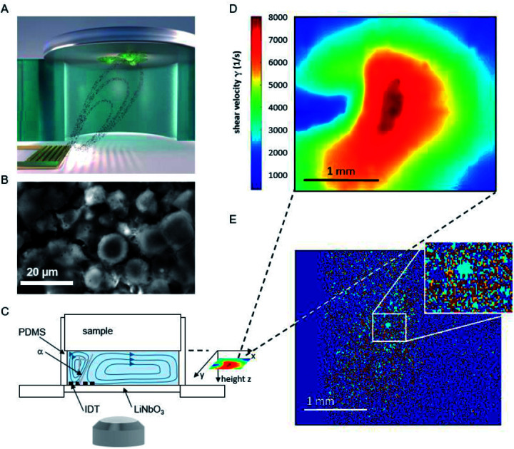
1. Introduction
Within the last decades the understanding of cell adhesion to various substrates under flow conditions has been of great interest for understanding physiological phenomena1 but also for medical purposes like tissue engineering,2 or acceptance of new biomaterials in the body3 and can be used to examine cell-substrate interaction for in vitro tests of medical implants. To ensure the osseointegration of medical implants, it is of particular interest to quantify the strength of cell adhesion to substrates under flow. Research in that direction today can be categorized by four techniques, namely centrifugation, spinning disk devices, flow chambers and microfluidics as summarized by Khalili et al.4 It began with a rotating disk in a fluid above a substrate with adhered cells,5–7 and rotating centrifugal systems.8 Changing the concept from rotating systems, flow chambers providing a linear variation of shear stress9 were established. Further downscaling led to the evolution of microfluidic assays and studies on single cell detachment10,11 and was further developed by designing multi-channel systems.12,13
Within the last years, miniaturized setups to study cell adhesion phenomena using Surface Acoustic Wave (SAW) induced flow have been established.14–16 Basically there exist two options to generate the flow. On the one hand, the cells, e.g. covered by a droplet of cell culture medium, and the SAW-generating transducer can be located on the same piezoelectric substrate. Due to the setup concept, the field of applications is very limited here. On the other hand, setups are employed, where cells being seeded on arbitrary substrates are exposed to the microfluidic flow jet induced by a SAW chip at the opposite site of a micro reactor. Such a closed chamber system enables to cover a wide range of shear velocities applied to an ensemble of cells without risking an unintended temperature increase or an unintended possible SAW-effect as reported earlier17 and in contrast to the first option. Employing this approach allows to quantify the influence of the acting shear forces on the detachment of single cells from a non-confluent cell layer. Within a single measurement studying one ensemble of cells the complete shear force range of interest is covered. Here, we used a setup as described earlier16 to investigate the adhesion behavior of SaOs-2 cells on medical implants under microfluidic shear flow. The analysis capability of the setup was tremendously enhanced by the implementation of custom software entitled ‘Particle Image Velocimetry De-Adhesion Correlation’ (PIVDAC) that correlates the detachment of the cells with the local shear velocity of the streaming fluid. To be more precise, the combination of scanning particle image velocimetry and fluorescence microscopy allows the correlation of local acting shear velocity and detachment for a cell population time dependently.
While meanwhile a considerable number of reports on cell detachment can be found, the role of the cell density finds sparsely particular attention.18 Therefore, we here focus additionally on this aspect in such in vitro experiments and compare experimental measurements with simulation results published earlier.19
2. Experimental
2.1. Surface acoustic wave driven flow system
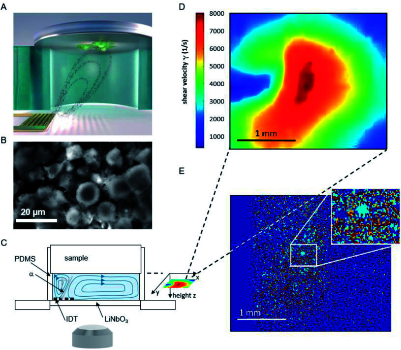
The basic principle of the setup is illustrated in Fig. 1. A cylindrical chamber with a volume of about 160 μl, filled with cell culture medium, and a titanium sample with adhered cells as top cover is positioned on a SAW-chip. On a piezoelectric LiNbO3 substrate a radio frequency (rf) signal (frequency ∼160 MHz, power P = 28 dBm) is applied to an interdigital transducer (IDT) with a periodicity of p = 25 μm resulting in a streaming towards the top cover as described earlier.16
Fig. 1. (A) Schematic illustration of the setup and sketched microfluidic streaming pattern generated by the interdigital transducer (golden comb like structure). (B) Micrograph of adhered cells on a titanium substrate. (C) Side view of the setup (D) shear map calculated from the sPIV measurement for a rf power of 28 dBm. (E) Superposition of the micrographs before and after 60 minutes of flow experiment. To visualize the difference in cell coverage of the substrate, the light blue area describes positions where cells detached, while red areas represent immobile cells. Area unoccupied by cells at the start of the experiment, but occupied at the end of the measurement, are colored orange.
The flow velocities as function of lateral and vertical position and the resulting distribution of the shear velocities were analyzed employing scanning particle image velocimetry (sPIV) based on Thielicke's time-resolved particle image velocimetry (PIV) software. Here, latex beads (Polysciences, Inc., Polybead® polystyrene, size 3 μm) were added to the fluid in the chamber, which follow the streamlines and are recorded using the high speed camera FASTCAM 1024PCI, Photron. The sPIV software enables to calculate the velocity distribution within particle image pairs, leading to the velocity field as function of the position above the SAW-chip. From measurements of velocity in several layers, the shear rate distribution in the plane as close as possible to the sample surface (∼20 μm) was extracted. The values range between ∼300 s−1 and ∼8000 s−1 and are interpolated from the large PIV grid of 39 × 23 pixels (72.5 × 109 μm pixel size) to obtain consistent resolution of the shear map and the micrographs of the adhered cells (2.59 μm pixel size, 923 × 1035 pixel, 2.39 × 2.68 mm), (Fig. 1D).
The fluorescence micrographs of the cells on the samples are recorded with an Axiovert 200 M (Zeiss) inverted microscope, a 2.5× objective and a digital camera (Hamamatsu Orca 5G) with 1344 × 1024 pixels. That implies an observable area of 3.48 mm × 2.65 mm, from which the sPIV analysed section is chosen (2.39 × 2.68 mm).
2.2. Cell culture
Saos-2 human bone osteosarcoma cells were purchased from CLS Cell Line Service GmbH and cultured using DMEM medium with stable glutamine, 3.7 g l−1 NaHCO3, 1.0 g l−1d-glucose (Biochrom) adding 50 ml fetal bovine serum (FBS Superior, S 0615, Biochrom), 10 ml HEPES 1 M (L 1613, Biochrom), 5 ml l-glutamine 200 mM (K 0283, Biochrom), 5 ml MEM vitamins 100× (K 0373, Biochrom), and 1 ml primocin (ant-pm-2, Invivogen) in humidified air containing 5% CO2 at T = 37 °C. During the flow experiments the temperature was kept constant at T = 37 °C.
2.3. Substrates
The medical titanium alloy (Ti Gr.5-ELI) material was obtained from Valbruna Edel Inox GmbH, Dormagen, Germany. The samples (discs with r = 5 mm, h = 2 mm) were sandblasted, which resulted in a surface roughness of Rq = 3.8 μm. Prior to the cell detachment experiments they were sterilized in an autoclave at 121 °C for 20 minutes.
2.4. Preparation procedure
From the harvested cells, a cell suspension with a concentration of approx. c = 300k cells ml−1 was prepared. For the experiments on the role of the cell density ρ, the cell concentration c was varied as described below. 1 μl of calcein green AM fluorescent dye (Invitrogen, 1 μg dissolved in 1 μl dimethyl sulfoxide) per ml of cell suspension is added. As only after removal of the acetoxymethyl (AM) esters by intracellular esterases the molecule is converted to a green fluorescent dye, only the living cells become visible in fluorescence microscopy (Ex. 485 nm/Em. 535 nm). 30 min after addition of the dye, 200 μl of cell suspension with approx. 60k cells were placed on the sample, forming a dome exceeding the volume of the chamber (160 μl). To allow the cells to subside and adhere, the sample is incubated for 60 min. Subsequently, the supernatant is gently replaced by pure medium to ensure the presence of adherent cells only. During the following 15 minutes the setup is installed on the microscope stage, before the microfluidic flow is initiated by application of a rf signal.
2.5. Image processing
To quantify the amount of cells, the images were converted to 8 bit black and white images using the software ImageJ provided by the NIH.20 For each stack of images of a single measurement an individual but constant threshold was set. The MATLAB-based script PIVDAC analyzes the percentage of cell covered area using these images, where white pixels were interpreted as cells and black pixels as background. The shear map calculated from the sPIV measurement at a rf power of P = 28 dBm covers an area of 2.68 × 2.39 mm2, while the observable area for cell adhesion measures 3.48 × 2.65 mm2. To receive matching sets of data, the shear map and the micrograph were aligned and the dimension of the matrix representing the micrographs were reduced to the same size. In the final step, the values of the shear velocity were interpolated to the same resolution as the micrograph (1035 × 923 pixels).
3. Results and discussion
3.1. Time and shear dependent detachment
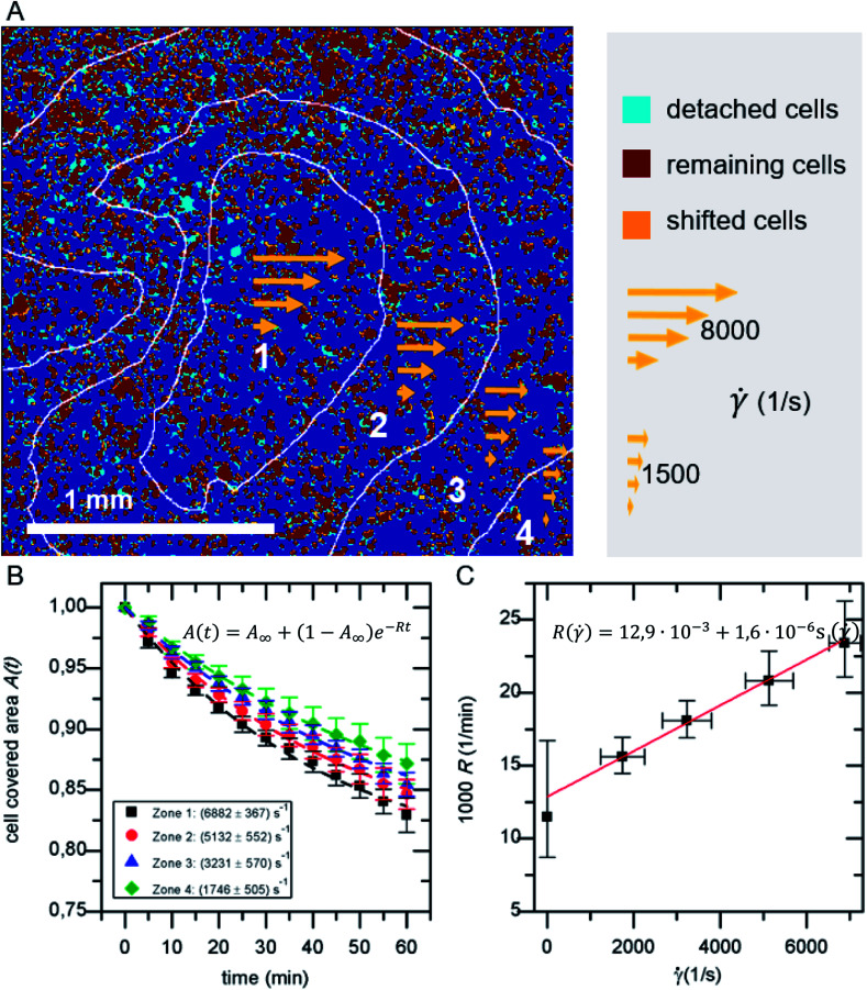
In a standard experiment, the adhesion behavior of SaOs-2 cells was observed over a time period of 60 min. The initial adhesion Ac,ini is the percentage of area covered with cells after a fixed period of incubation with regard to the total imaged area Atot. It ranges between 5–60% depending on the cell concentration c and cell density ρ. For every frame the cell covered area A(t) normalized to the initial adhesion Ac,ini is analyzed. A binning of the shear velocity map results in four zones of acting shear velocities as given in Table 1.
Shear velocities.
| Zone | Mean ± standard deviation of shear velocity (1/s) |
|---|---|
| 1 | 6882 ± 367 |
| 2 | 5132 ± 552 |
| 3 | 3231 ± 570 |
| 4 | 1746 ± 505 |
The detachment rate R turned out to be constant after a very short time after the beginning of each measurement, as soon as loosely bound cells, that persisted the washing step, are removed. Therefore, A(t) for the whole sample, as well as for each bin of shear velocity can be described by an exponential function as shown in Fig. 2:
| A(t) = A∞ + (1 − A∞)e−Rt | 1 |
where A∞ is the remaining coverage after a long time period.
Fig. 2. (A) Example for the classification of detached, shifted and remaining cells in overlay with shear velocity bins. (B) Cell covered area A(t) for the four shear velocity zones. (C) Detachment rate R( ). The data points in B and C represent normalized mean values and their standard deviation of five independent preparations and detachment experiments.
Be aware, that A∞ is a proportion referred to the area covered initially Ac,ini, while Ac,ini itself refers to the total area Atot.
3.2. Thermodynamic model
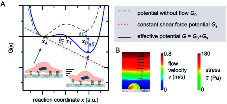
The mechanical event of cell adhesion and detachment is also a thermodynamic process. To apply a minimal model as in other earlier publications7,21,22 following the pioneering works of Bell,23 we consider the cell adhesion molecules either in adherent (A) or unbound (B) state. An according Gibbs potential can be approximated by a potential with two minima as illustrated in Fig. 3. An additional linear component represents a constant shear force due to the interaction with the acoustically driven medium flow. To describe the adhesion and detachment process we apply Kramers' theory of reaction kinetics.
Fig. 3. (A) Gibbs potential as a function of an appropriate reaction coordinate. The two local minima at xA and xB correspond to the adhered and detached state of a cell adhesion molecule. (B) FEM simulations show that the stress inside an attached homogenous elastic hemisphere can be very inhomogeneous [adapted from ref. 24].
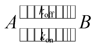
In an equilibrium of adherent (A) and free (B) bonds, the reaction equation with the coefficients kon for adhesion and koff for detachment reads as follows.
 |
2 |
The number of bonds in state A changes with time as
 |
3 |
The detachment rate koff depends on the reaction's activation energy EAA, which is the potential difference between state A and the transition state between A and B, according to the Arrhenius equation. Rebinding kon scales with the potential difference EAB between state B and the transition state, accordingly.
 |
4 |
Applying a constant external force F, in our case the shear flow, the potential G is adjusted by a linear term to G̃ = G − Fx. The reaction's activation energy follows to be ẼA = EA − Fx̃T (see Fig. 3A). Therefore the new rate constant k̃off results as
 |
5 |
The applied force F is the part acting on a single bond of the overall shear force acting on a cell. The bond here can be described as a spring with spring constant k expanded by the distance z.
 |
6 |
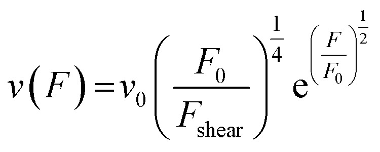
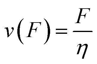
From here on we follow an earlier argumentation21 to correlate the detachment rate of the bonds of a cell to the detachment rate of the entire cell. Due to their calculations, there are three regimes for the ratio of the applied force F and the adhesive force. In all our experiments included in this study, we intentionally applied comparably mild shear forces in the order of magnitude of the cell adhesion forces, as we consider this the most interesting regime. However, to relate these experiments with other reported ones and to complete the model, we here briefly summarize the model for the whole force range. The regimes differ in influence on the cells' peeling velocity v as described in eqn (7)–(9). Forces slightly exceeding a threshold force FC, which is the minimum force required to peel cells of by shear flow, are declared as low forces. Here, F0 is a characteristic force scale. The peeling velocity increases linearly in the low force regime scaling with a constant factor depending on the equilibrium detachment rate Re. Under the impact of significantly larger forces, we distinguish between a low velocity (strong adhesion) and a high velocity limit. In the medium force regime, where the adhesion is strong enough to account for a low peeling velocity, the thermo-activated process is still in progress. This induces an exponential relation between shear force and peeling velocity. When the shear force reaches a value, where the potential barrier vanishes and Kramer's theory fails, the cells directly follow the flow (high forces), and the progression is linear again. Thus, peeling velocity and shear force can be related as follows.21low force – low velocity
 |
7 |
medium force – low velocity (strong adhesion)
 |
8 |
high force – high velocity limit
 |
9 |
The shear force F acting on an object depends linearly on the fluid's shear velocity , the viscosity η and its area β parallel to the flow.
| F = ηβ | 10 |
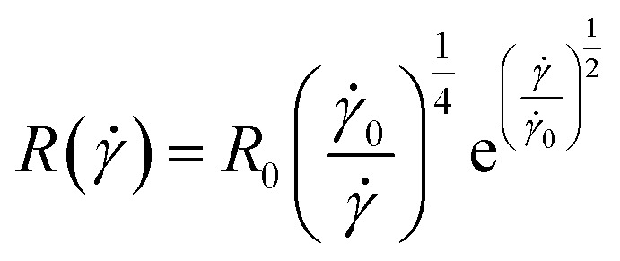
Approximating the peeling velocity v as the diameter of the attached cell divided by the time constant of the detachment process results in a linear dependency of the peeling velocity and the cell detachment rate R. Thus, the eqn (7)–(9) also relate the detachment rate R and the shear velocity . We introduce a characteristic shear velocity c for simplification.low shear velocity
| R( ) = R0 ( − c) | 11 |
medium shear velocity
 |
12 |
high shear velocity
 |
13 |
The temporal devolution of the number of adherent cells can thus be described by an exponential decay as also found experimentally (see Fig. 2).
| A(t) = A∞ + (1 − A∞)e−R( )t | 14 |
3.3. Comparison of model and experiment
As shown in Fig. 2A in the superposition of shear map and micrograph stacks of adhered cells, by grouping the shear velocity in four bins, zones of different acting mean shear velocity, and thus force, are introduced. This allows to determine A(t) for each zone independently. The resulting graphs (see Fig. 2B) display mean values of five independent identical experiments, still follow eqn (1) and show a clear dependence on the shear velocity. With increasing shear velocity (from zone 4 to 1) the amount of detached cells increases significantly.
Eqn (14) is used to describe the flow-induced detachment experiments to determine the appropriate regime of shear forces (low, medium or high). The experiments in this study reflect the low shear force regime, as we find R( ) = R0( − c) as shown in Fig. 2C. In contrast to earlier reports we find a positive R( = 0). This most likely originates from the inverted layout of our setup with cells adhering at the facing down surface of the lid of the microreactor.
To understand whether an almost linear dependency is reasonable and due to a lack of published data on SaOs-2 cells on titanium implants, we here compare our results to those on various cell-substrate-combinations and classify the applied shear forces according to our model. In doing so, we start with the most unsimilar combination reported by Décavé et al.,25 who studied shear flow-induced detachment of D. discoideum cells from glass. The authors also predict and show an exponential behavior at high shear velocities. The shear stress in our experiments ranges from 0.2 Pa to 5.6 Pa, while the above mentioned study covers a range up to 20 Pa.
As a rough first order approach to compare the detachment of different cell types on different substrates, we compare the intrinsic detachment rate R0 under static conditions. While in the reported study cited above R0 = 1.2 × 10⁻² min−1, we determine it to be R0 = 1.5 × 10⁻⁴ min−1, which is only 1% as high. From this fact, we deduce that our cells adhere much stronger to the surface. Additionally, we apply lower shear velocities. Thus, low detachment rates and a linear slope, as predicted for a low force regime in the studied shear velocity range, seem reasonable, while the shear stress applied in the report cited above21 ranges in the medium force regime.
In an earlier similar publication García et al.1 describe a spinning disk device to investigate osteoblast-like cell adhesion on fibronectin coated glass. They report a non-linear decrease in the fraction of adherent cells vs. shear stress in a range of shear stress similar and above ours up to 10 Pa. Again, the here studied SaOs-2 cells seem to exhibit stronger adhesion, as the adherent cells are reduced to ∼60% at ∼5 Pa in both our case and García's at shorter incubation (15 min) and shorter exposure to shear (10 min). Therefore, those experiments reach up to the regime of medium forces. The stronger adhesion presumably originates from the higher surface roughness of the titanium substrate used in our study.
For drawing further comparisons, we consider the work of Fritsche et al.26 who measured bone cell adhesion using a spinning disc device. Comparable to our setup the authors studied bone cells adhered on titanium, but on a mirror-like polished surface and at far higher shear stresses (≈50 Pa). These experimental conditions and the linear increase of detachment with the shear velocity suggest the categorization into the high force regime (high force, low adhesion).
A substrate of comparable surface roughness to ours (Rq = 3.8 μm) is found in the work of Deligianni et al.27 Therein, cell detachment of human bone marrow cells on hydroxylapatite substrates of different surface roughness from Rq = 0.7 μm to 4.7 μm were studied at very high shear rates up to 60 Pa using a rotating disc device. In the shear range of our experiments, no detachment occurs. The apparent much stronger adhesion in the study of Deligianni et al. is most likely a result of the significantly longer incubation (4 h), smaller cell size and the similarity of the artificial bone material substrate to actual human bones.
Concluding, we can classify the specific cell-substrate combination and shear field we applied in the low force regime due to the mild application of shear flow and the conducive roughness of the surface for cell adhesion. This specific combination of cell-type, substrate and applied shear force regime has to be taken into account for each study. Thus, to bring the cells in their cell-type-specific low force regime it is necessary to ensure hydrodynamic comparability which includes careful adjustment of cell adhesion relevant parameters. Or, from another point of view, such measurements allow to assess the strength of cell-substrate combinations by their sensitivity towards shear forces. Furthermore, low detachment rates can result from the fact that, starting from a certain adhesion strength depending on the substrate conformation, cells can adapt to the application of shear forces. The integrins binding to the extracellular matrix respond to shear stress with a greater binding affinity.28 Moreover, cells develop more filopodial extensions responsive to low shear flow compared to their static state and start to round up only at high shear stress.29 In the relatively long time interval of our measurements (135 min from seeding to the end of the measurement), this effect is probably not negligible and another possible repressing factor for the increase of detachment with shear velocity.
However, the presented method allows to determine the detachment rate R( ) for whole cell ensembles simultaneously with a variable shear field and bears the potential to represent a platform for a variety of exciting experimental studies, e.g. on time dependent shear force modulation. In the last section of the paper, we demonstrate its potential to study the role of cell density for shear flow induced detachment.
3.4. Application to the role of cell density for shear induced detachment
While there are several studies on shear dependent detachment of cells at relatively low cell density, there is lack of systematic studies on shear flow induced cell detachment as a function of the cell density on the samples. Furukawa et al. address this question by comparing the cell detachment in a spinning disc device of sparsely seeded cells to a confluent monolayer of cells and find a significantly stronger resistance against shear stress in the confluent case.18 Other authors mention that cells do not influence each other if less than 7% of the substrate area is covered with cells.25 However, many studies investigate cell detachment for surface coverage in the range of 50%.7
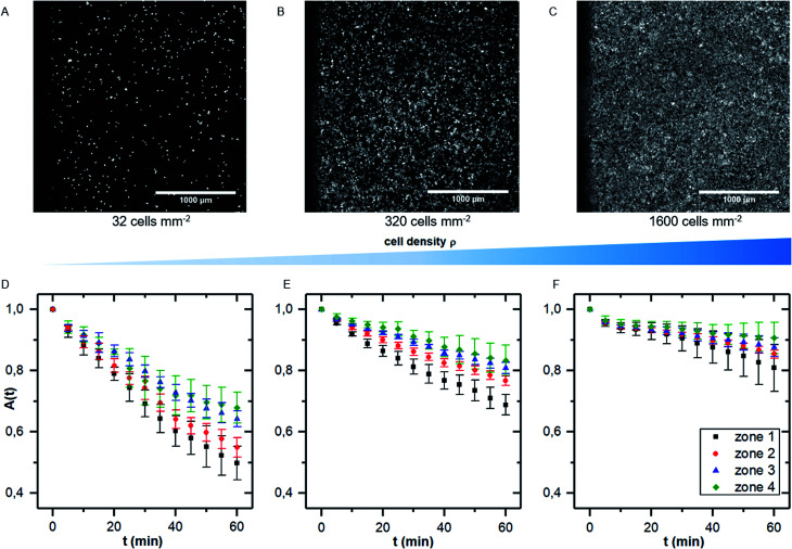
We here performed detachment experiments as described above but varying the cell density, while all other parameters are kept constant. Fig. 4A–C show micrographs of the selected cell densities and the time dependent surface coverage A(t) with the shear zones employing PIVDAC. These detachment kinetics show a significant decrease of the detachment rate with increasing cell density. To avoid removal of whole pieces of tissue and to exclude a significant effect of cell–cell-adhesion, we do not include measurements of confluent cell layers in the further analysis steps to compare with previous simulations. These simulations simply do not account for such effects. However, for confluent cell layers within the error bars we even do not see cell detachment at all in the applied regime of shear forces (data not shown).
Fig. 4. (A–C) micrographs of samples with increasing cell density (A: 32 cells per mm2, B: 320 cells per mm2 and C: 1600 cells per mm2). (D–F) Cell covered area A(t) for the four shear velocity zones for measurements as shown in (A–C). The data points represent normalized mean values and standard deviations of five independent preparations and detachment experiments.
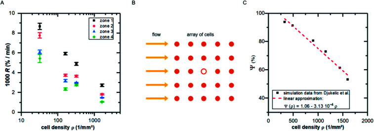
Fitting the cell covered area A(t) with eqn (1), we obtain the detachment rate R as function of cell density and shear stress as shown in Fig. 5A. To understand the dependency of R(ρ) we use results of finite element simulations published earlier19 and combine it with the minimal thermodynamic model proposed above.
Fig. 5. (A) Detachment rate R as function of cell density ρ for the four shear velocity zones. The shown values are mean ± standard deviation of five independent preparations. (B) Illustration of the top view of an idealized cell array under flow: the cell in the middle (hollow symbol) experiences lower shear forces due to the presence of neighboring cells. (C) Influence factor Ψ (see eqn (15)) for the cell in the middle of the cell array in B as function of cell density [adapted from ref. 19].
To do so, we use eqn (5) and consider the applied force as a function of cell density F(ρ). Following our previous publication,19 with increasing ρ the influence of neighboring cells on a distinct cell increases, reducing the effective acting forces compared to an identical situation but without neighboring cells. This is a pure geometrical effect, reducing the flow velocities of ‘downstream’ cells and thus the acting tension within these cells. Due to the design of these simulations, they are only valid in the regime below confluence, as they do not take into account cell–cell-contacts. As we here use the main result of that study, we briefly summarize it in the following paragraph.
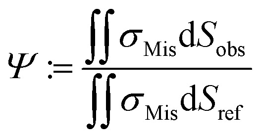
By employing numerical Finite Element Method (FEM) simulations of deformable objects under shear flow, we investigated the occurring stress within elastic adherent cells and the influence of neighboring cells on these quantities. The influence factor Ψ is defined as
 |
15 |
where σMis is the von-Mises stress and Sobs and Sref are the surface of the observed cell surrounded by neighbors and the surface of the same cell under identical conditions but isolated, respectively.19
Here, we now assume that the influence factor is a proportional measure for the shear forces acting on the cell adhesion molecules
| F(ρ) = F0Ψ ≈ F0(Ψ0 − mϱ) | 16 |
Here, m is a constant depending on the fluid velocity and the cell shape, while m increases with increasing fluid velocity. Combining eqn (5) and (16) then results in
 |
17 |
Assuming  as described above, further results in
| R ∼ e−mϱ. | 18 |
Comparing Fig. 5A with the predicted relation of eqn (18) seems convincing. While for zone 1 (with the highest fluid velocities and shear forces) the prediction fits perfectly to the data, in zones of lower shear force some deviations appear which are most likely linked to ‘nominal’ cell density, i.e. the seeded cell density, and the actual cell density. For clarity we here stress that the specific value of m depends on the fluid velocity and the exact value of R depends on koff, what in turn implicitly depends very strong on the cell substrate combination. However, considering the fact that in the simulations we assume perfectly shaped, evenly distributed, homogeneous elastic objects without any biochemical interaction, while the data in Fig. 5A show the result of living cells seeded at different concentrations, is astonishing.
4. Conclusion
In this study, we investigated cell adhesion on medical implant materials under shear flow by using the software PIVDAC, which correlates local shear velocities and time-dependent detachment of cells. Using PIV, we are able to provide detailed information on local shear velocities in a closed microfluidic system. Combing these data with cell adhesion under constant flow conditions for a given amount of time and applying Kramers' theory of reaction kinetics to the detachment process, we are able to determine the specific time and shear force detachment rate R. This can now be used to estimate the adhesion force of various cells to substrates.
Thus, our method provides a powerful dynamical platform for various applications like, e.g. cell detachment under dynamically modulated shear fields. As a first application, and additionally to the demonstration of the method, our main finding is the strong dependence of cell detachment on the cell density. In agreement with earlier theoretical predictions, these experimental data strongly suggest to always take the cell density into account to compare results of different cell adhesion and detachment studies under flow.
Conflicts of interest
There are no conflicts to declare.
Supplementary Material
Acknowledgments
The authors thank the “Deutsche Forschungsgemeinschaft (DFG)” for the financial support of this work under the contract (WI 1091/19-1) “Erkenntnistransferprojekt Antibakterielle und abriebarme Beschichtung von Gleitflächen in orthopädischen Implantaten”. Moreover, the authors like to acknowledge funding by Nanosystems Initiative Munich (NIM) and thank the Center for NanoScience (CeNS), the Bavaria California Technology Center (BaCaTec) and the Augsburg Centre for Innovative Technologies (ACIT) for additional financial support for this project. The authors thank Sidonie Lieber and Alexander Hartwig for technical assistance.
References
- García A. J. Ducheyne P. Boettiger D. Biomaterials. 1997;18:1091–1098. doi: 10.1016/S0142-9612(97)00042-2. [DOI] [PubMed] [Google Scholar]
- Saltzman W. M. and Kyriakides T. R., in Principles of Tissue Engineering 4th edn, 2014, pp. 385–406 [Google Scholar]
- Goldstein A. S. Juarez T. M. Helmke C. D. Gustin M. C. Mikos A. G. Biomaterials. 2001;22:1279–1288. doi: 10.1016/S0142-9612(00)00280-5. [DOI] [PubMed] [Google Scholar]
- Khalili A. Ahmad M. Int. J. Mol. Sci. 2015;16:18149–18184. doi: 10.3390/ijms160818149. [DOI] [PMC free article] [PubMed] [Google Scholar]
- Weiss L. Exp. Cell Res. 1961;8:141–153. doi: 10.1016/0014-4827(61)90345-7. [DOI] [PubMed] [Google Scholar]
- Fuhrmann A. Engler A. J. Biophys. J. 2015;109:57–65. doi: 10.1016/j.bpj.2015.06.003. [DOI] [PMC free article] [PubMed] [Google Scholar]
- Maan R. Rani G. Menon G. I. Pullarkat P. A. Phys. Biol. 2018;15:046006. doi: 10.1088/1478-3975/aabc66. [DOI] [PubMed] [Google Scholar]
- Reyes C. D. García A. J. J. Biomed. Mater. Res., Part A. 2003;67A:328–333. doi: 10.1002/jbm.a.10122. [DOI] [PubMed] [Google Scholar]
- Usami S. Chen H.-H. Zhao Y. Chien S. Skalak R. Ann. Biomed. Eng. 1993;21:77–83. doi: 10.1007/BF02368167. [DOI] [PubMed] [Google Scholar]
- Couzon C. Duperray A. Verdier C. Eur. Biophys. J. 2009;38:1035–1047. doi: 10.1007/s00249-009-0506-1. [DOI] [PubMed] [Google Scholar]
- Cheung L. S. L. Zheng X. Stopa A. Baygents J. C. Guzman R. Schroeder J. A. Heimark R. L. Zohar Y. Lab Chip. 2009;9:1721. doi: 10.1039/B822172C. [DOI] [PubMed] [Google Scholar]
- Lu H. Koo L. Y. Wang W. M. Lauffenburger D. a. Griffith L. G. Jensen K. F. Anal. Chem. 2004;76:5257–5264. doi: 10.1021/ac049837t. [DOI] [PubMed] [Google Scholar]
- Tang Z. Akiyama Y. Itoga K. Kobayashi J. Yamato M. Okano T. Biomaterials. 2012;33:7405–7411. doi: 10.1016/j.biomaterials.2012.06.077. [DOI] [PubMed] [Google Scholar]
- Hartmann A. Stamp M. Kmeth R. Buchegger S. Stritzker B. Saldamli B. Burgkart R. Schneider M. F. Wixforth A. Lab Chip. 2014;14:542–546. doi: 10.1039/C3LC50916H. [DOI] [PubMed] [Google Scholar]
- Bussonnière A. Miron Y. Baudoin M. Bou Matar O. Grandbois M. Charette P. Renaudin A. Lab Chip. 2014;14:3556. doi: 10.1039/C4LC00625A. [DOI] [PubMed] [Google Scholar]
- Stamp M. Jötten A. Kudella P. Breyer D. Strobl F. Geislinger T. Wixforth A. Westerhausen C. Diagnostics. 2016;6:38. doi: 10.3390/diagnostics6040038. [DOI] [PMC free article] [PubMed] [Google Scholar]
- Brugger M. S. Stamp M. E. M. Wixforth A. Westerhausen C. Biomater. Sci. 2016;4:1092–1099. doi: 10.1039/C6BM00125D. [DOI] [PubMed] [Google Scholar]
- Furukawa K. S. Ushida T. Nagase T. Nakamigawa H. Noguchi T. Tamaki T. Tanaka J. Tateishi T. Mater. Sci. Eng., C. 2001;17:55–58. doi: 10.1016/S0928-4931(01)00336-8. [DOI] [Google Scholar]
- Djukelic M. Wixforth A. Westerhausen C. Biomicrofluidics. 2017;11:024115. doi: 10.1063/1.4979295. [DOI] [PMC free article] [PubMed] [Google Scholar]
- Schneider C. A. Rasband W. S. Eliceiri K. W. Nat. Methods. 2012;9:671–675. doi: 10.1038/nmeth.2089. [DOI] [PMC free article] [PubMed] [Google Scholar]
- Garrivier D. Décavé E. Bréchet Y. Bruckert F. Fourcade B. Eur. Phys. J. E. 2002;8:79–97. doi: 10.1140/epje/i2002-10010-8. [DOI] [PubMed] [Google Scholar]
- Schwarz U. S. Safran S. A. Rev. Mod. Phys. 2013;85:1327–1381. doi: 10.1103/RevModPhys.85.1327. [DOI] [Google Scholar]
- Bell G. Science (80-) 1978;200:618–627. doi: 10.1126/science.347575. [DOI] [PubMed] [Google Scholar]
- Djukelic M., Modellierung und Simulation der Wechselwirkung zwischen adhärenten Zellen und Fluid bei kleinen Reynoldszahlen, Master thesis, University of Augsburg, 2015 [Google Scholar]
- Décavé E. Garrivier D. Bréchet Y. Fourcade B. Bruckert F. Biophys. J. 2002;82:2383–2395. doi: 10.1016/S0006-3495(02)75583-5. [DOI] [PMC free article] [PubMed] [Google Scholar]
- Fritsche A. Luethen F. Lembke U. Finke B. Zietz C. Rychly J. Mittelmeier W. Bader R. Materwiss. Werksttech. 2010;41:83–88. doi: 10.1002/mawe.200900547. [DOI] [Google Scholar]
- Deligianni D. D. Katsala N. D. Koutsoukos P. G. Missirlis Y. F. Biomaterials. 2000;22:87–96. doi: 10.1016/S0142-9612(00)00174-5. [DOI] [PubMed] [Google Scholar]
- Shyy J. Y.-J. Circ. Res. 2002;91:769–775. doi: 10.1161/01.RES.0000038487.19924.18. [DOI] [PubMed] [Google Scholar]
- van Kooten T. G. Schakenraad J. M. Van der Mei H. C. Busscher H. J. J. Biomed. Mater. Res. 1992;26:725–738. doi: 10.1002/jbm.820260604. [DOI] [PubMed] [Google Scholar]


