Abstract
The fabrication of light-weight and high-performance polymer foams, especially special engineering plastic foams, with complicate three-dimensional (3D) geometry remains a great challenge worldwide. In this study, microcellular polyetherimide (PEI) bead foams with 3D geometry and high expansion ratio were successfully prepared by using supercritical CO2 (scCO2)/ethanol (EtOH) as co-blowing agent. The co-foaming mechanism and the effect of EtOH on foaming properties were studied. The results indicated that the addition of EtOH increased the solubility of co-blowing agent in PEI matrix by promoting the interactions between them, thus broadening the foaming temperature window and significantly increasing the expansion ratio, up to 7.12. The obtained PEI foams with 3D geometry had the cell size of 58.54 μm and cell density of 3.66 × 10⁶ cells per cm3, as well as excellent mechanical strength, e.g., tensile stress of 6.59 MPa and compression stress of 6.87 MPa. This co-foaming technology also has a great potential in fabricating other high-performance polymer foams.
Light-weight and three-dimensional PEI bead foam products with microcellular structure and good mechanical properties fabricated by self-designed mould assisted scCO2/ethanol co-foaming technology.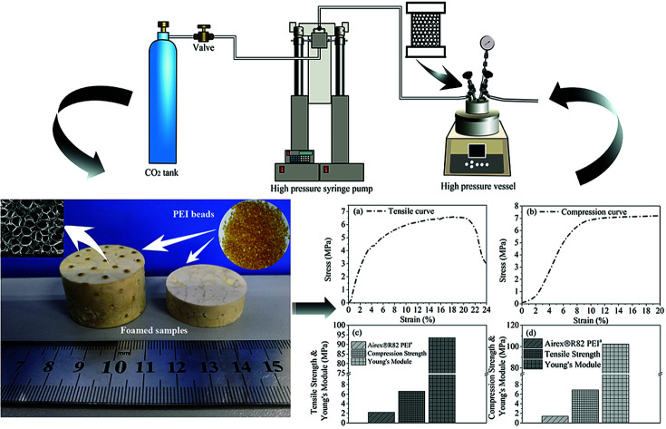
1. Introduction
Polymer foams have been widely used in industry, agriculture, packaging, construction, transportation, etc., because of their light weight, excellent specific strength, heat insulation and cost-saving features over their solid analogs.1,2 Currently, the most widely used polymer foams are general plastic foams, mainly including polystyrene (PS), polythene (PE), polypropylene (PP), et al.3,4 However, due to the poor performance of the matrix, general plastic foams usually show some drawbacks, e.g. low mechanical strength, poor thermal stability and flame retardancy, thus are hardly to meet the requirements of high-tech industries like aerospace and aeronautic,5 military and electronic fields.6 It is urgent to develop lightweight and high-performance polymer foams, especially special engineering plastic foams, used for high-tech industries.
Polyetherimide (PEI) is an amber and amorphous high-performance engineering thermoplastic with excellent processability, intrinsic flame retardancy and less smoke generation, and can be long-term used at the temperature above 200 °C. However, ascribing to the high processing temperature of PEI (near to 400 °C), it is quite difficult to find a proper chemical blowing agent for PEI due to its degradability or explosibility at so high temperature. Therefore, PEI foams are usually prepared by physical foaming methods using inert gas including carbon dioxide (CO2) and nitrogen (N2) as blowing agent. At present, the main fabrication methods for PEI foams are solid-state intermittent foaming technology, melt extrusion foaming technology and reactive extrusion foaming technology, among which solid-state intermittent foaming technology5,7 is the widely used one, and has also been applied in the preparation of some other high-performance polymer foams like polyether-ether-ketone (PEEK),8,9 polyphenylene sulfide (PPS)10,11 and polysulfone (PSU).12,13 For this technology, the polymer resins are first saturated with supercritical CO2 (scCO2) for a quite long time at quite low temperature, then foaming by quickly increasing the temperature.14 Yu, et al.15 adopted this method to get PEI foaming film with the cell size of 180 nm and cell density of 1.58 × 10¹³ cells per cm3. The saturation time for such PEI film with only a thickness of 0.45 mm was more than 20 h at 8 MPa and 40 °C, and the foaming temperature was 170 °C. With the increasing of the thickness of PEI samples used for foaming, the saturation time must be greatly increased. For example, the saturation time for 1.5 mm thickness PEI sample was above 300 h at 5 MPa and room temperature,5 and the expansion ratio and cell size of the obtained PEI foaming products were 2.5 and 30 nm to 4 μm, respectively. Limited by so long saturation time of solid-state intermittent foaming technology, the PEI foam products are mostly one-dimensional sheets, resulting in that PEI foams even with micro/nano-cellular structures still have narrow applications.16,17 Then, Goel et al. proposed a developed solid-state foaming technology,18i.e. polymer resin was first saturated in scCO2 at a relatively high temperature, over Tg or Tm for amorphous or semi-crystalline polymer, followed by rapid pressure quench. In this way, the saturation time could be greatly reduced because of the higher diffusion rate of scCO2 at high temperature, but the solubility of CO2 was decreased, which was liable to led to the undesired concentration gradient of CO2 in the polymer matrix, especially the thick polymer samples, making the fabrication of PEI foams with high expansion ratio and uniform cell structure quite difficult.
Accordingly, to prepare PEI and PEI based composite foams with 3D shapes and satisfied cell structure, we developed a mould assisted batch foaming technology by using scCO2 as blowing agent. In this foaming process, polymer granules were initially filled in a stainless steel mould with many micro nozzles, through which scCO2 could be injected. After being saturated at high temperature for a relatively short time, the bead foam products were obtained via rapidly depressurization of the stainless steel mould. To further improve the cell structure and expansion ratio of our PEI bead foam products, in this paper, ethanol (EtOH) was further introduced as co-blowing agent with scCO2, and the foaming mechanism and foaming behaviors of PEI with scCO2/EtOH were investigated. The foaming technology described in this paper was high efficiency and could possibly be applied to fabricate other high-performance thermoplastic foams, like PEEK, PSU and PPS, etc., with 3D geometry and uniform cell structure.
2. Experimental
2.1. Materials
PEI (ULTEM 1000) with Tg of 215 °C was purchased from Sabic, America. CO2 was supplied by Xuyuan Co., Ltd. (China) with purity higher than 99%. EtOH was supplied by Chengdu Changlian Co., Ltd. (China). All materials were used without further purification.
2.2. Preparation of PEI foamed beads and bead foamed parts
After being dried in a drying oven at 120 °C for 4 h, 50 g PEI granules were placed into a 0.5 L stainless steel vessel, then the vessel was put into a high pressure vessel with certain EtOH (0%, 15%, 30%, 45% and 60%, respectively, with mol ratio to scCO2) in it at room temperature. The vessel was first flushed with 0.2 MPa CO2 for about 1 min to exhaust the air inside, and then immediately filled with CO2 to certain pressure (3, 4, 5 and 6 MPa, respectively), followed by heating to different temperature (175 °C, 183 °C, 191 °C, 199 °C, 207 °C and 215 °C) within 10 min and saturating at this temperature for 90 min. The final saturation pressure was 8 MPa, 10 MPa, 12 MPa and 14 MPa, respectively. After that, the vessel was rapidly depressurized (5 MPa s−1), and PEI foamed beads were obtained. The mol of scCO2 was calculated using appropriate PVT data from saturation pressure, saturation temperature and vessel volume.19,20
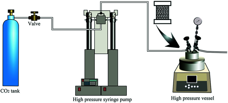
For bead foamed parts, the PEI granules were first filled into a stainless steel mould with micro nozzles. Then, the mould was put into the high pressure vessel. After being saturated at a certain condition, the bead foamed parts were obtained via rapidly depressurization (5 MPa s−1) of the high pressure vessel. The foaming process was shown in Fig. 1.
Fig. 1. Schematic illustration of the mould assisted batch foaming process.
2.3. Molecular dynamic (MD) simulation
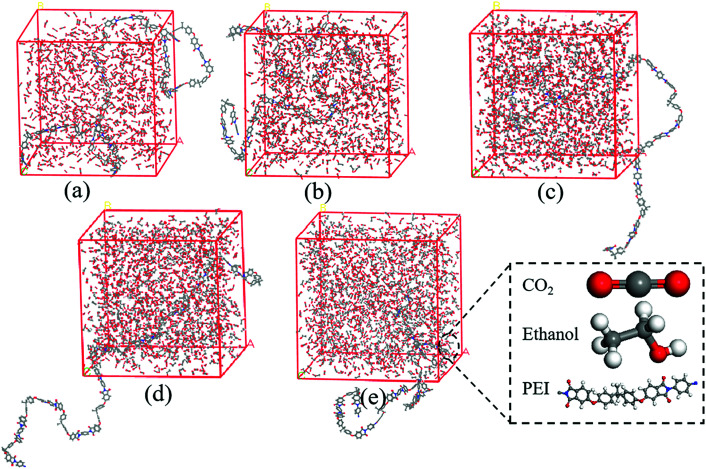
In order to better understand the interactions between scCO2/EtOH co-solvent and PEI chains, MD simulation of PEI/CO2/EtOH systems was studied using Materials Studio 8.0. The simulations were carried out with the COMPASS force field, and PEI molecular chains with 10 repeat units were built due to the limited computing resources. After the optimization of the chain geometry, cubic box containing one PEI chain, 1000 CO2 and different number of EtOH molecules were constructed in Amorphous Cell tools with a periodic boundary condition, the snapshot of cubic box containing different EtOH molecules was shown in Fig. 2, and the corresponding parameters were shown in Table 1. After annealing treated from 300 K to 500 K at 10 K min−1 ramp rate for 5 times, 100 ps NPT MD simulation was carried out at 190 °C and 12 MPa using Forcite tools. The interaction energy between PEI and scCO2/EtOH was obtained using the mean value of the last 10 configurations.
Fig. 2. Snapshot of cubic box containing different molecules. (a) PEI + 1000CO2; (b) PEI + 1000CO2 + 150EtOH; (c) PEI + 1000CO2 + 300EtOH; (d) PEI + 1000CO2 + 450EtOH; (e) PEI + 1000CO2 + 600EtOH.
Systems of PEI/CO2/EtOH in MD simulations.
| Compositions | Number of PEI chain | Number of CO2 | Number of EtOH |
|---|---|---|---|
| PEI/scCO2 | 1 | 1000 | 0 |
| PEI/CO2–15% EtOH | 1 | 1000 | 150 |
| PEI/CO2–30% EtOH | 1 | 1000 | 300 |
| PEI/CO2–45% EtOH | 1 | 1000 | 450 |
| PEI/CO2–60% EtOH | 1 | 1000 | 600 |
2.4. Characterization
2.4.1. Solubility of blowing agents
PEI dried granules were placed in a high pressure vessel (0.5 L) at 190 °C and 12 MPa for different time. After the vessel was cooled by cold water to ambient temperature, the PEI pellets were quickly taken out and immediately weighted on a Mettler AE240 analytical (Labx Co., Ltd., USA) with ±10 μg accuracy to measure the CO2 and CO2/EtOH adsorbed. Five measurements were performed for each sample.
2.4.2. Differential scanning calorimetry (DSC)
Glass transition behaviors of PEI with different blowing agent were performed on a Q20 DSC apparatus (TA Instruments Co., Ltd., New Castle, USA) in nitrogen atmosphere from 40 °C to 240 °C at the heating rate of 20 °C min−1. To avoid the escape of foaming agent during the testing, the samples were placed into a sealed crucible.
2.4.3. High pressure capillary (HP-capillary)
High pressure capillary rheological behaviors of PEI foaming systems were carried out on Rosand RH7D HP-capillary rheometer (Malvern Instrument, UK) with a long die (L/D = 16) at 340 °C from 100–2000 s−1. In order to avoid the escape of foaming agent during the testing process, PSU was used to seal both sides of the charging barrel, and PEI/CO2 or PEI/CO2/EtOH foaming systems must be immediately transferred into the charging barrel of the HP-capillary rheometer once being taken out from the high pressure vessel.
2.4.4. Scanning electron microscope (SEM)
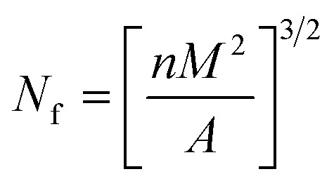
Cell structure of PEI foam was analyzed using Inspect F SEM instrument (FEI Co., Ltd., USA) at 0.5 torr and 20 kV. The image processing software Nano Measurer was used to calculate the cell density (Nf, number of cells per unit foamed polymer volume) and the average cell diameter. Nf was determined using eqn (1).
 |
1 |
where n is the number of cells in the SEM micrograph, M is the magnification factor, and A is the area of the micrograph (in cm2).
2.4.5. Expansion ratio
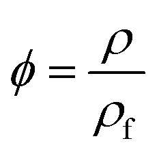
The expansion ratio ϕ of the foam was calculated using eqn (2).21
 |
2 |
where ρ and ρf are the densities of unfoamed and foamed PEI, respectively, and can be tested on a MDMDY-350 automatic density instrument (Meidi analytical Co., Ltd., China).
2.4.6. Mechanical properties
Mechanical properties including tensile strength and compression strength of PEI foamed parts were tested at ambient temperature on an Instron 5567 Tensile & Compression Tester (Instron Co., Ltd., United States). The tensile strength was conducted at a speed of 5 mm min−1 with a 60 mm × 10 mm × 5 mm rectangular sample according to GB/T 9641-1988/ISO 1926-1979, while the compression strength testing of a cylinder sample with diameter of 30 mm and height of 10 mm was conducted at a crosshead speed of 2 mm min−1 according to GB/T 8813-2008/ISO 844: 2004.
3. Results and discussion
3.1. Solubility of CO2/EtOH
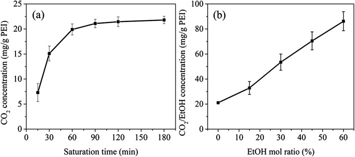
The solubility of blowing agent in a polymer matrix is an important factor that affects the cell structure of the final foam. The solubility of CO2 in PEI at 190 °C and 12 MPa for different saturation time was investigated, as shown in Fig. 3a. The CO2 concentration was defined as the mass ratio of CO2 to PEI matrix. Apparently, with the increasing of saturation time, CO2 concentration in PEI increased and reached the equilibrium after 90 min, i.e. 21.5 mg g−1 PEI. With the further addition of EtOH into scCO2 system, the solubility parameter as well as the polarity of scCO2 could be significantly improved ascribing to the hydrogen-bond interactions between CO2, EtOH and polymer matrix.27,28 This was beneficial to the increase of the diffusivity of CO2 and would lower the equilibrium saturation time of the co-blowing agent to less than 90 min. However, to better compare the solubility of CO2/EtOH co-blowing agent in PEI and only CO2 in PEI, the saturation time for the system with EtOH was still fixed to 90 min. It could be clearly seen from Fig. 3b that CO2/EtOH co-blowing agent presented greatly increased solubility in PEI matrix compared with CO2. For example, with the addition of 60% mol ratio EtOH, the solubility of co-blowing agent increased to 86.2 mg g−1 PEI, almost 4 times than that of CO2. Zhao et al.22 had reported that the hydroxyl groups of ethanol could connect with the ether group of polymer. So, here, EtOH might interact with both CO2 and PEI, thus increasing the plasticization effect of blowing agent on PEI and resulting in the increase of the flexibility of PEI molecular chains as well as the greater solubility of CO2/EtOH mixture in PEI matrix. The increased content of blowing agent would help to obtaining PEI 3D foams with high expansion ratio.
Fig. 3. CO2 concentration vs. saturation time (a) and CO2/EtOH equilibrium concentration vs. EtOH mol ratio (b).
3.2. Plasticization effect of blowing agent
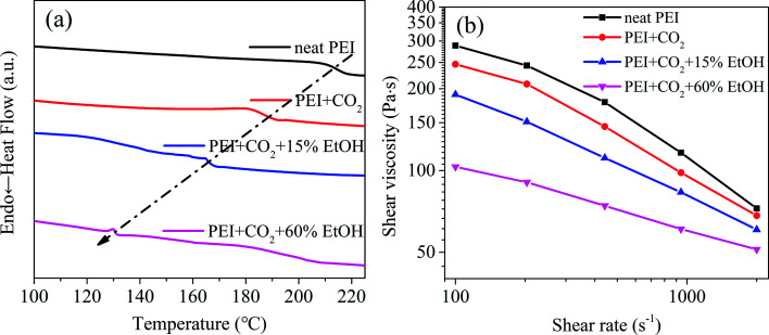
To further illustrate the plasticization effect of blowing agent on PEI molecules, the DSC heating curves (Fig. 4a) and the high pressure capillary curves (Fig. 4b) of PEI with CO2 and CO2/EtOH were analyzed. It could be found from Fig. 4a that a significant decrease of Tg appeared with the dissolving of CO2, i.e. from 215 °C to about 190 °C. CO2 is a lewis acid, the carbon atom lacking of electrons in CO2 molecule can act as electron acceptor, so has special interactions with the groups like phenyl group and carbonyl group in polymer chains.23,24 In this way, CO2 could act as a small molecular plasticizer for PEI and magnified the distances of PEI molecules, augmenting their free volumes and weakening their attractions, thus increasing their mobility and reducing the Tg of PEI. At the same CO2 concentration, the addition of EtOH further decreased the Tg of the foaming system, and the more the EtOH content, the more the decrease of Tg. For example, the addition of 60% mol ratio EtOH led to the decrease of Tg from about 190 °C to 130 °C, strongly confirming the improved plasticization effect of CO2/EtOH on PEI. This was beneficial to decrease the foaming temperature, i.e. reducing the foaming energy.
Fig. 4. DSC curves (a) and high pressure capillary curves (b) of different PEI/blowing agent systems.
The plasticization effect of blowing agent also influenced the melt viscosity of the foaming system. As shown in Fig. 4b, compared with neat PEI, the shear viscosity of PEI/blowing agent system apparently reduced. Especially when 60% mol ratio of EtOH was introduced, the shear viscosity of the system was almost insensitive to shear rate, i.e. changed little with the increase of shear rate.
Overall, it would be a best choice to overcome the problem existed in the present PEI foaming technology by using scCO2/EtOH as co-blowing agent.
3.3. Foaming behavior of PEI/scCO2/EtOH system
3.3.1. Effect of EtOH concentration
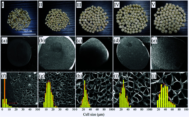
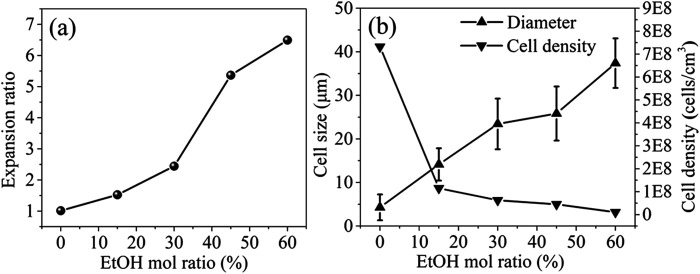
Up to now, the maximum expansion ratio reported for PEI foam by using scCO2 or scN2 as blowing agent was no more than 5 and the foaming temperature and pressure were quite high,25,26 which are hardly to be accepted by industries. In this paper, EtOH was adopted as co-blowing agent with scCO2, and ascribing to its plasticization effect on PEI molecules with scCO2, the foaming temperature was largely decreased to about 190 °C. Fig. 5 showed the photos and SEM micrographs of PEI foamed beads using scCO2/EtOH as blowing agent, and the corresponding expansion ratio, cell size and cell density of the beads with different EtOH mol ratio were depicted in Fig. 6. Obviously, PEI granules only using scCO2 as blowing agent showed partially foaming behavior, while with the addition of EtOH, all the formed beads exhibited smooth surface with fine closed cell structure, as well as significant increases in both expansion ratio and cell size. When EtOH mol ratio increased from 15% to 60%, the expansion ratio and cell size of the foamed beads increased from 1.53 to 6.49 and 14.15 to 37.39 μm, respectively, but the cell density decreased, from 1.15 × 10⁸ cell per cm3 to 1.02 × 10⁷ cell per cm3. As studied previously, EtOH had obvious plasticization effect on PEI, so could further decrease the surface tension of PEI and reduce the resistance of cell growth, leading to the enlarged cell size and the increased porosity of the foams.27
Fig. 5. Macrographs (I–V) and SEM micrographs of PEI foamed beads (a–j) obtained at 190 °C and 12 MPa using CO2/EtOH as blowing agent. EtOH concentration: (a and f) 0%; (b and g) 15%; (c and h) 30%; (d and i) 45%; (e and j) 60% mol ratio.
Fig. 6. Expansion ratio (a), cell size and cell density (b) of PEI foamed beads obtained at 190 °C and 12 MPa with different EtOH mol ratio.
To give a deep understanding on the increase of expansion ratio with the addition of EtOH, the interactions between CO2/EtOH co-blowing agent and PEI molecular chains were studied with the help of MD simulations, as shown in Fig. 2. The interaction energy between CO2/EtOH and a PEI molecular chain, which could quantitatively predict their compatibility, was evaluated from the energy of each system, as expressed in eqn (3).27
| Einter = EPCE − (EPEI + ECE) | 3 |
where Einter refers to interaction energy, EPCE represents the total energy of a PEI chain and CO2/EtOH blowing agent. EPEI and ECE are the individual energy of a PEI chain and CO2/EtOH blowing agent. The values of EPEC, EPEI and ECE can be obtained from MD simulations and are the average values of the related properties in the final 10 configurations.
As shown in Table 2, under the same foaming conditions, with the increase of EtOH mol ratio, Einter gradually decreased, even to a negative value when EtOH mol ratio was above 30%. Positive Einter indicates the endothermic reaction. For PEI/CO2 system, Einter was 545.59 kJ mol−1, confirming the relatively low adsorption capacity of PEI molecules on CO2. That was why partially foaming behavior happened for this system. While with the addition of EtOH (15% mol ratio), Einter decreased from 545.59 kJ mol−1 to 163.97 kJ mol−1, meaning that the compatibility between PEI and the blowing agent enhanced attributing to the synergistic effect of EtOH on both PEI and CO2. In this way, CO2/EtOH co-blowing agent could better exert its plasticization effect and foaming efficiency, making the expansion ratio of PEI foamed beads slightly increased to 1.53. Further increasing EtOH mol ratio from 30% to 60%, Einter values became negative, i.e. from −564.58 kJ mol−1 to −1302.78 kJ mol−1, indicating the occurrence of the exothermic reaction during the foaming process, possibly caused by the increase of the bonding energy between PEI and scCO2/EtOH solvent, which helped to enhance the solubility of scCO2/EtOH in PEI matrix. As a result, the expansion ratio of PEI foamed beads greatly increased, from 2.44 to 6.49.28 The variation trend of Einter was in good agreement with the rising tendency of expansion ratio from thermodynamical view, suggesting that MS simulations might be an alternative way to predicting foaming behaviors.
Interaction energy between a single PEI chain and CO2–EtOH co-blowing agent obtained from MD simulations.
| Compositions | E PCE (kJ mol−1) | E PEI (kJ mol−1) | E CE (kJ mol−1) | E inter (kJ mol−1) |
|---|---|---|---|---|
| PEI/CO2 | 7753.67 | 787.61 | 6420.47 | 545.59 |
| PEI/CO2–15% EtOH | 7188.69 | 780.04 | 6244.68 | 163.97 |
| PEI/CO2–30% EtOH | 12 101.28 | 6998.86 | 5667.01 | −564.58 |
| PEI/CO2–45% EtOH | 4302.21 | 842.68 | 4678.33 | −1218.80 |
| PEI/CO2–60% EtOH | 2327.62 | 587.90 | 3042.50 | −1302.78 |
Considering the comprehensive cell structure of PEI foamed beads, 45% mol ratio of EtOH was chose in the letter analyses.
3.3.2. Effect of foaming temperature
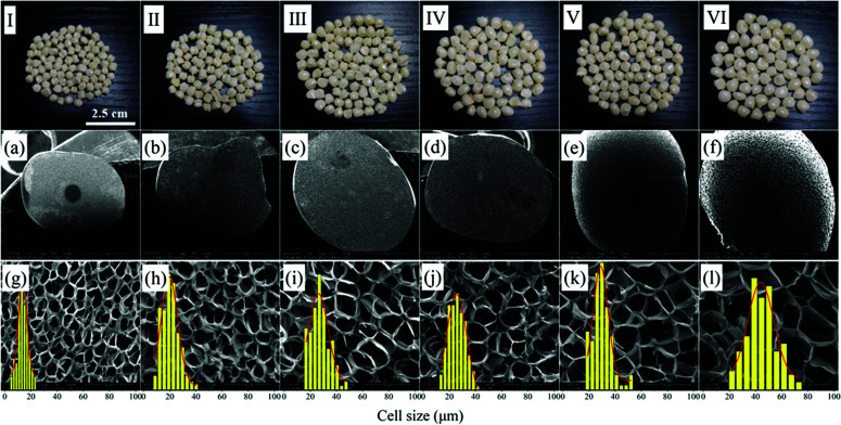
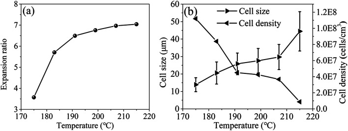
The effects of foaming temperature on cell structures were investigated at the foaming pressure of 12 MPa and EtOH mol ratio of 45%. The photos and SEM micrographs of PEI foamed beads were shown in Fig. 7, and the corresponding expansion ratio, cell size and cell density at different foaming temperature were depicted in Fig. 8. As reported by Miller et al., the minimum foaming temperature was equivalent to the effective Tg of a polymer/solvent system.5,7 The introduction of EtOH enhanced the solubility of scCO2/EtOH in PEI matrix, thus improving the movement of PEI chains and reducing the Tg of the foaming system. In this way, the minimum foaming temperature of system could be reduced to about 175–215 °C, much lower than those reported in present ref. 5 and 9. It could be seen from Fig. 7 and 8 that with the increase of the foaming temperature, the cell size and expansion ratio of PEI foamed beads increased, while the cell density decreased, due to the accelerated movement of PEI molecular chains with the temperature, which weakened the resistance of the matrix to the bubble growth. For example, when temperature increased from 175 °C to 191 °C, the expansion ratio and cell size significantly increased from 3.57 and 13.87 μm to 6.50 and 25.57 μm, respectively. However, with the further increase of the temperature, up to 215 °C, the expansion ratio only had a slight increase, from 6.50 to 7.04, indicating that PEI matrix now was insensitive to the foaming temperature from 191 °C to 215 °C, thus a wide foaming temperature window could be obtained for PEI by using EtOH as co-blowing agent with scCO2.
Fig. 7. Macrographs (I–VI) and SEM micrographs of PEI foamed beads (a–l) obtained at different foaming temperature. (a and g) 175 °C; (b and h) 183 °C; (c and i) 191 °C; (d and j) 199 °C; (e and k) 207 °C; (f and l) 215 °C.
Fig. 8. Expansion ratio (a), cell size and cell density (b) of PEI foamed beads obtained at different temperatures with co-blowing agents.
3.3.3. Effect of saturation pressure
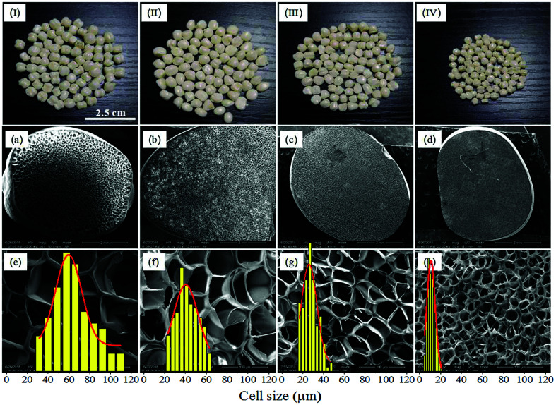
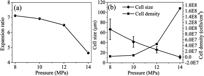
The effect of saturation pressure was investigated at 5 MPa s−1 depressurization rate, 190 °C foaming temperature and 45% EtOH mol ratio. After being saturated at 190 °C for 1.5 h, the inner saturation pressures were 8 MPa, 10 MPa, 12 MPa and 14 MPa, respectively. The optical images and the cell morphologies of PEI foamed beads were shown in Fig. 9, and the corresponding expansion ratio, cell size and cell density at different saturated pressure were depicted in Fig. 10. The results showed that PEI foamed beads with polished surfaces and fine cells were obtained at each saturation pressure. With the increase of saturation pressure, the cell size of the foamed beads decreased, from 66.54 μm to 11.36 μm, while the cell density increased, from 2.27 × 10⁶ to 1.69 × 10⁸ cells per cm3. It was well known that the higher the saturation pressure, the more the blowing agent will be dissolved in a polymer matrix. According to the homogeneous nucleation theory, higher blowing agent concentration means greater degree of supersaturation and lower energy barrier to nucleation, so more cells per unit volume will be generated and higher cell density in the foamed product will be achieved.29 The error bar in Fig. 10b reflected the distribution of the cell size, which became narrow with the increase of saturation pressure, indicating that higher saturation pressure was helpful to improve the uniformity of cells because of the increased cell density over higher supersaturation. When more cell nuclei formed and simultaneously grew in a limited space, the differences in cell growth should be decreased, undoubtly resulting in more uniform and smaller cell size.
Fig. 9. Macrographs (I–IV) and SEM micrographs of PEI foamed beads (a–h) obtained at different saturation pressure. (a and e) 8 MPa; (b and f) 10 MPa; (c and g) 12 MPa; (d and h) 14 MPa.
Fig. 10. Expansion ratio (a), cell size and cell density (b) of PEI foamed beads obtained at different saturation pressure.
It should be noticed that with the increase of saturation pressure, the expansion ratio of the foamed beads continuously decrease, from 7.12 to 4.63, and the decrease extent enlarged at the saturation pressure above 14 MPa (PInitial = 6 MPa) (Fig. 10a). As discussed in previous section, the hydrogen atom (H) in –OH group of EtOH could form strong hydrogen bonds with both scCO2 and PEI,30 thus improving the solubility of co-blowing agent in PEI matrix. Under the co-plasticization and co-foaming effects of scCO2 and EtOH on PEI, PEI foamed beads with improved cell structure and high expansion ratio (7.12) were obtained. However, the increase of the saturation pressure was realized by injecting more scCO2 and EtOH into the high pressure vessel, when other foaming conditions were fixed. The increased blowing agent in system would surely enhance the nucleation ability of the foaming system, leading to the formation of smaller cells, but also imposed greater plasticization effect on PEI molecular chains, which possibly weakened the strength of the PEI cell walls and made them unable to keep so many gases in the cells after pressure release. As a result, the expansion ratio of the foamed beads reduced. This effect might be quite obvious when saturation pressure was above 14 MPa, so the expansion ratio decreased greatly.
3.4. Macromorphology and mechanical properties
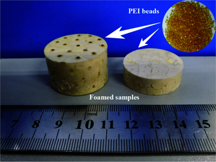
Through above analyses and to simultaneously obtaining high expansion ratio and cell density while maintaining cell size as small as possible, the PEI bead foaming products were fabricate at the foaming conditions of 190 °C, 8 MPa and 45% EtOH using a stainless steel mould by applying 5 MPa s−1 of depressurization rate. Fig. 11 showed the PEI foamed samples that just fully filled in the stainless mold. It could be seen that the PEI raw granules were amber-like, while the foam part with high expansion ratio looked white.
Fig. 11. Photograph of PEI granules and PEI bead foaming samples.
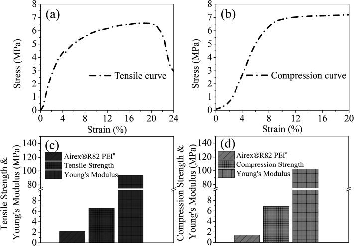
Fig. 12 showed the tensile and compression behaviors of the PEI foamed samples. Airex®R82 PEI, a commercial PEI foamed product, with the tensile stress of 2.2 MPa and the compression stress of 1.4 MPa was provided by Airex company in Switzerland. Obviously, PEI bead foaming samples showed higher mechanical properties (tensile stress: 6.59 MPa; compression stress: 6.87 MPa) than those of the commercial Airex®R82 PEI, ascribing to the creation of more uniform microcellular cells in our PEI matrix, with cell size of 58.54 μm and cell density of 3.66 × 10⁶ cells per cm3 (Fig. 13). This confirmed again that the bead foaming technology proposed in this study was a promising approach for the fabrication of the special engineering thermoplastic foams with complicated 3D shape and high performances.
Fig. 12. Tensile (a) and compression (b) stress–strain curves, and the corresponding tensile (c) and compression (d) properties of the PEI bead foaming samples.
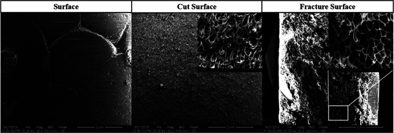
Fig. 13. SEM micrographs of the surface, cut surface and fracture surface of PEI bead foams parts.
The inter-bead bonding and the intra-bead bonding force determined the mechanical properties of the final parts.31 The bead-to-bead sintering behaviors, including the surface, cut surface and fracture surface, of the PEI bead foaming samples were investigated using FE-SEM, as shown in Fig. 13. It could be seen that the foamed samples presented a good surface quality, and no inter-bead bonding boundary was observed on the cut surface and fracture surface of the foamed samples, implying the strong local sintering quality among the foamed PEI beads.32 The fracture surface after the tensile test again showed that the breaking of PEI bead foams almost occurred intra the bead, further identifying the strong inter-bead sintering.33
4. Conclusions
PEI bead foams with high expansion ratio and 3D shape were prepared by using supercritical CO2 (scCO2)/ethanol (EtOH) as co-blowing agent based on our developed mould assisted batch foaming technology. The results showed that the addition of EtOH could significantly increase the interactions between blowing agent with PEI chains, thus helping to enhance the compatibility and improving the solubility of CO2/EtOH mixture in PEI. In this way, CO2/EtOH mixture could efficiently exert their plasticization effect on PEI molecular chains, decreasing Tg of PEI and making PEI foamed at relatively lower temperature. The increased CO2/EtOH in PEI matrix also promoted more nuclei formed, leading to the better foaming of PEI as well as the increased expansion ratio of the final foamed beads, up to 7.12. At proper foaming conditions and with appropriate CO2/EtOH content, PEI foamed parts with 3D geometry, cell size of 58.54 μm and cell density of 3.66 × 10⁶ cells per cm3 were obtained. These PEI foamed parts presented excellent inter-bead sintering behavior, thus having good mechanical properties (6.59 MPa tensile strength and 6.87 MPa compression strength) and a great potential in the applications of some high-tech industries like aerospace, special ship et al., where 3D structure foam materials with light weight, high strength and heat resistance properties are urgently required.
Conflicts of interest
There are no conflicts of interest to declare.
Supplementary Material
Acknowledgments
This work was support by National Natural Science Foundation of China (5171001071) and the Program of Innovative Research Team for Young Scientists of Sichuan Province (2016TD0010). We would like to thank the Analytical & Testing Center of Sichuan University for providing Materials Studio 8.0 and we would be grateful to Daichuan Ma for his help of computational simulation.
References
- Park C. B., Polymeric Foams: Science and Technology, CRC Press, 2006 [Google Scholar]
- Okolieocha C. Raps D. Subramaniam K. Altstädt V. Eur. Polym. J. 2015;73:500–519. doi: 10.1016/j.eurpolymj.2015.11.001. [DOI] [Google Scholar]
- Altan M., Thermoplastic Foams: Processing, Manufacturing, and Characterization, 2018 [Google Scholar]
- Wang G. Chen X. Liu P. Bai S. J. Appl. Polym. Sci. 2016;134:44356. [Google Scholar]
- Miller D. Kumar V. Polymer. 2011;52:2910–2919. doi: 10.1016/j.polymer.2011.04.049. [DOI] [Google Scholar]
- Cafiero L. Iannace S. Sorrentino L. Eur. Polym. J. 2016;78:116–128. doi: 10.1016/j.eurpolymj.2016.03.014. [DOI] [Google Scholar]
- Miller D. Chatchaisucha P. Kumar V. Polymer. 2009;50:5576–5584. doi: 10.1016/j.polymer.2009.09.020. [DOI] [Google Scholar]
- Yang Q. Zhang G. Ma Z. Li J. Fan X. J. Appl. Polym. Sci. 2015;132:42576. [Google Scholar]
- Nemoto T. Takagi J. Ohshima M. Polym. Eng. Sci. 2010;50:2408–2416. doi: 10.1002/pen.21766. [DOI] [Google Scholar]
- Itoh M. Kabumoto A. Furukawa Rev. 2005;28:32–38. [Google Scholar]
- Ma Z. Zhang G. Yang Q. Shi X. Li J. Fan X. Polym. Compos. 2016;37:2527–2540. doi: 10.1002/pc.23443. [DOI] [Google Scholar]
- Li Z. Jia Y. Bai S. RSC Adv. 2018;8:2880–2886. doi: 10.1039/C7RA11760D. [DOI] [PMC free article] [PubMed] [Google Scholar]
- Sun H. Mark J. E. J. Appl. Polym. Sci. 2002;86:1692–1701. doi: 10.1002/app.11070. [DOI] [Google Scholar]
- Costeux S. J. Appl. Polym. Sci. 2015;131:1–16. [Google Scholar]
- Yu H. Lei Y. Yu X. Wang X. Liu T. Luo S. J. Appl. Polym. Sci. 2015;132:42325. [Google Scholar]
- Abbasi H. Antunes M. Velasco J. I. Eur. Polym. J. 2015;69:273–283. doi: 10.1016/j.eurpolymj.2015.06.014. [DOI] [Google Scholar]
- Zhou C. Vaccaro N. Sundarram S. S. Li W. J. Cell. Plast. 2012;48:239–255. doi: 10.1177/0021955X12437984. [DOI] [Google Scholar]
- Goel S. K. Beckman E. J. Polym. Eng. Sci. 1994;34:1137–1147. doi: 10.1002/pen.760341407. [DOI] [Google Scholar]
- Tsivintzelis I. Pavlidou E. Panayiotou C. J. Supercrit. Fluids. 2007;42:265–272. doi: 10.1016/j.supflu.2007.02.009. [DOI] [Google Scholar]
- Angus S., Armstrong B. and de reuck K. M., International Thermodynamic Tables of the Fluid State : Carbon Dioxide, Oxford, 1985 [Google Scholar]
- Rezvanpanah E. Ghaffarian Anbaran S. R. Di Maio E. Carbon. 2017;125:32–38. doi: 10.1016/j.carbon.2017.09.035. [DOI] [Google Scholar]
- Zhao N. Zhu C. Howe Mark L. Park C. B. Li Q. J. Appl. Polym. Sci. 2015;132:11962–11972. doi: 10.1002/app.41873. [DOI] [Google Scholar]
- Kajiya D. Imanishi M. Saitow K. I. J. Phys. Chem. B. 2016;120:785–792. doi: 10.1021/acs.jpcb.5b11740. [DOI] [PubMed] [Google Scholar]
- Kazarian S. G. Vincent M. F. Bright F. V. Liotta C. L. Eckert C. A. J. Am. Chem. Soc. 1996;118:1729–1736. doi: 10.1021/ja950416q. [DOI] [Google Scholar]
- Sorrentino L. Aurilia M. Iannace S. Adv. Polym. Technol. 2011;30:234–243. doi: 10.1002/adv.20219. [DOI] [Google Scholar]
- Zhai W. Feng W. Ling J. Zheng W. Ind. Eng. Chem. Res. 2012;51:12827–12834. doi: 10.1021/ie3017658. [DOI] [Google Scholar]
- Hu D. D. Gu Y. Liu T. Zhao L. J. Supercrit. Fluids. 2018;140:21–31. doi: 10.1016/j.supflu.2018.05.017. [DOI] [Google Scholar]
- Hu D. Sun S. Yuan P. Zhao L. Liu T. J. Phys. Chem. B. 2017;119:3194–3204. doi: 10.1021/jp5130052. [DOI] [PubMed] [Google Scholar]
- Di Maio E. Kiran E. J. Supercrit. Fluids. 2018;134:157–166. doi: 10.1016/j.supflu.2017.11.013. [DOI] [Google Scholar]
- Hu D. CIESC J. 2018;69:555–562. [Google Scholar]
- Lee E. K., PhD thesis, School of Graduate Studies, 2010 [Google Scholar]
- Nofar M. Ameli A. Park C. B. Mater. Des. 2015;83:413–421. doi: 10.1016/j.matdes.2015.06.052. [DOI] [Google Scholar]
- Zhai W. Kim Y.-W. Jung D. W. Park C. B. Ind. Eng. Chem. Res. 2011;50:5523–5531. doi: 10.1021/ie101753w. [DOI] [Google Scholar]


