Abstract
Exploitation of the intrinsic electrical properties of particles has recently emerged as an appealing approach for trapping and separating various scaled particles. Initiative particle manipulation by dielectrophoresis (DEP) showed remarkable advantages including high speed, ease of handling, high precision and being label-free. Herein, we provide a general overview of the manipulation of polystyrene (PS) beads and related particles via DEP; especially, the wide applications of these manipulated PS beads in the quantitative evaluation of device performance for model validation and standardization have been discussed. The motion and polarizability of the PS beads induced by DEP were analyzed and classified into two categories as positive and negative DEP within the time and space domains. The DEP techniques used for bioparticle manipulation were demonstrated, and their applications were conducted in four fields: trapping of single-sized PS beads, separation of multiple-sized PS beads by size, separation of PS beads and non-bioparticles, and separation of PS beads and bioparticles. Finally, future perspectives on DEP-on-a-chip have been proposed to discriminate bio-targets in the network of microfluidic channels.
Exploitation of the intrinsic electrical properties of particles has recently emerged as an appealing approach for trapping and separating various scaled particles.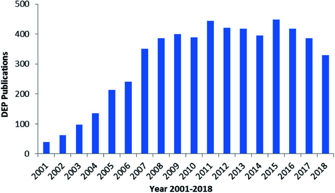
1. Introduction
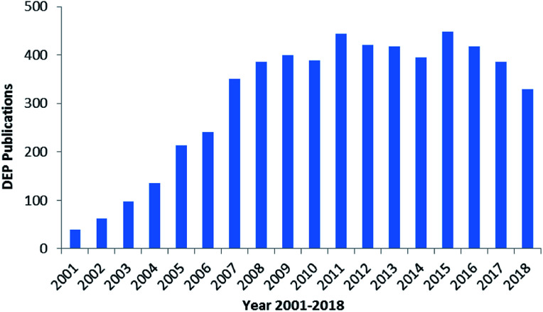
The manipulation of various scaled particles is of significant interest in biomedical applications. The manipulation techniques mostly include electrophoresis (EP),1 dielectrophoresis (DEP),2,3 optical tweezing,4 Raman spectroscopy,5,6 impedance (IM) spectroscopy,7,8 hydrodynamic flows9,10 and acoustic traps;11 DEP has attracted significant attention to control particles due to its high selectivity and rapidity in manipulation.12,13 DEP was extensively used in 2005 and then reached a culmination in 2016.16,17 There are nearly 6k reports on DEP since 2000, as shown in Fig. 1.14 The number of studies reported on DEP has significantly increased due to the development of micro-fabrication and related techniques. There was an explosion in the number of studies reported on DEP in 2003–2008, and a steady plateau was achieved in 2008–2018.
Fig. 1. Studies reported on DEP from 2000 to 2018.14.
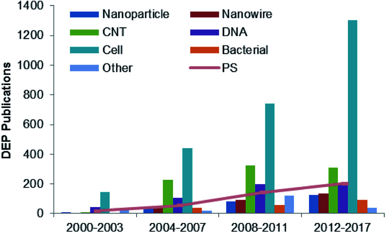
DEP is based on the fact that particles with different electrical characteristics behave differently in a nonuniform electric field. The DEP force provides an efficient and convenient way to control particles, especially for selective manipulation and rapid separation. It has been used in industrial food safety, clinical cell sorting, infection diagnosis, and enrichment of particle populations for drug development. DEP has been used in the trapping process,15 alignment,16,17 and isolation and separation of various sized particles,18 which are applied in a wide range of clinical, biological and environmental applications. Some particles, such as cells, nanoparticles (NPs),19 nanotubes (NTs),20 nanowires,21 nanorods,22 DNA23 and viruses,24 are typically used in the DEP manipulation, as shown in Fig. 2. As a standard particle, polystyrene (PS) beads are widely used in the performance and quantitative evaluation of DEP systems to demonstrate the feasibility of the proposed design.
Fig. 2. Studies reported on DEP over 2000–2017 for various types of DEP particles.20–25.
Considering the various types of biomedical and biotechnological applications, it is apparent that in situ diagnostics for cells and bacteria are highly significant in DEP manipulation. Mansor et al. presented a historical review of single-cell electrical property analysis and its development from classical techniques to recent advances in microfluidic techniques.26 Kasetsirikul et al. further reviewed DEP as a malaria diagnostic method for both detection of malaria and separation of infected erythrocytes, especially the malaria parasite-infected red blood cells (RBCs).27 Adekanmbi's group provided a much better and deeper understanding on how DEP could be utilized to manipulate diseased cells such as those associated with malaria, cancer, dengue, anthrax and human African trypanosomiasis.28 Páez-Avilés et al. summarized both the DEP and impedance analysis (IA)-combined approaches and the latest relevant improvements, such as those in terms of selectivity, sensitivity, detection time, and conductivity variation enhancements, focusing on bacteria concentration and detection.29 Viefhues's group focused on DNA manipulated by DEP and presented an important theory in DEP applications, a recent review of DNA applications and discussion of the current challenges and future tasks.30
Herein, we reviewed studies mainly reported between 2000 and 2018 on the DEP manipulation of particles. This review is distinct from the previous reviews since we have solely focused on the DEP manipulation of PS beads. A brief background on the DEP theory and simulation of PS beads has been discussed. The detailed analysis of the PS beads experimentally manipulated by DEP has been divided into two sections: trapping of single-sized PS beads and separation of the PS beads and mixed particles (e.g. non-bioparticles, DNA, cells, bacteria, and viruses). Finally, the DEP techniques have been proposed for biosensing applications in the future.
2. Theoretical background and simulation
2.1. Motion of the PS beads
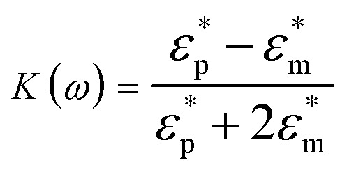
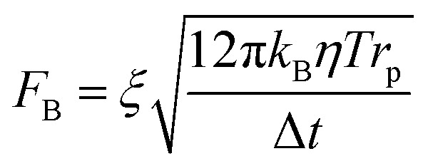
DEP is the motion of dielectrically polarized particles in non-uniform electric fields. Unlike direct current (DC) electric fields,31 alternating current (AC) electric fields can be used to manipulate many types of particles in different media by simply adjusting the AC electric field parameters (e.g., magnitude, frequency, wave shape, wave symmetry and phase) and eliminating the influence of electrostatic forces. Manipulation of nano/micro-scaled particles within a DEP chip can generally be categorized based on the types of force fields used for the manipulation. When suspended in a fluid medium in the microchannel, an electrically polarizable particle experiences FDEP, which makes the cell move to the local field direction.16 If the dielectric constant of the particle is different from that of the surrounding medium, the particle moves toward the high intensity (pDEP) or low intensity (nDEP) part of the electric field. In addition to FDEP, the particle is subjected to other forces, such as Stokes' drag force, FDrag,32,33 gravity force, FGra,34 buoyancy force, FBuo, AC electroosmosis35 (ACEO) force, FEo, electrophoretic (EP) force, FEP,35 and Brownian force, FB,36,37 as listed in Table 1. The Clausius–Mossotti (CM) factor K(ω) is related to the electric field frequency (ω = 2πf); rp is the radius of a particle, σ is the conductivity and ε* is the complex permittivity of particles and the suspending medium (ε* = ε – jσ/ω, where the subscripts p and m represent the particles and suspending medium, respectively). c is a non-dimensional factor accounting for the wall effects (c = 1 for spherical), η is the dynamic viscosity of the fluid,37v is fluid velocity,33ρ is density, V is volume, q is the effective charge, and E is the electric field intensity. ξ is a Gaussian random vector, kB is the Boltzmann constant, T is the absolute temperature, and Δt is the time step used in the numerical integration scheme. Cb is the coefficient that depends on the distance among particles and the length of the particle chains (3 < Cb< 1000).
Force on the PS beads in the microfluids applied with an AC electric field.
| Force | Electric field | Scale of PS beads | Formula | No. |
|---|---|---|---|---|
| DEP | 10 kHz to 10 MHz | Micro/nano | F DEP = 2πrp3εmRe[K(ω)]∇E2 | (1) |
| ||||
| Stokes' drag | High flow rates | Micro/nano | F Drag = 6πcηrp(νm − νp) | (2) |
| Gravity and buoyancy | Unlimited | Unlimited |

|
(3) |
| ACEO | AC (0–100 kHz) | Micro |

|
(4) |
| EP | High (DC or AC in low frequency) | Charged | F EP = qE | (5) |
| Brownian | Low | Nano |
|
(6) |
| Interaction | 10 kHz to 10 MHz | — | F chain = −CbπεmRe[K(ω)]2rp2E2 | (7) |
2.1.1. Gravity and buoyancy vs. Brownian motion
The Stokes' drag force FDrag depends on the flow rates in microfluids; if the flow rate ranges from 10 nL min−1 to 10 μL min−1, it provides drag forces in the range from 0.07 to 70 pN on a 1 μm PS bead.38 The drag force can be apparently neglected considering that particles move slowly in a droplet. If a 10 μm PS bead falls into a DEP area by gravity and buoyancy, it experiences a force of approximately 50 fN. At a low frequency (<100 kHz), the ACEO exerts a significant force on particles, resulting in convection of the trapped particles to the centre of electrodes. This effect is strongest when the electric double layer (EDL) is presumed to be in quasi-equilibrium, corresponding to a frequency significantly below the charge relaxation time of an electrolyte.39 The use of larger voltages prevents the hindering effects of Brownian motion; however, excessive voltages may cause unwanted effects, including electrolysis, electrochemical reactions or Joule heating, which can be overcome using a high frequency (>1 MHz).40
As abovementioned, gravity can be ignored if the particle density is close to that of the fluid and the diameter of the particle is small.41 Moreover, Brownian motion becomes important as the particle size decreases to the nano-scale. The relative magnitude of Brownian force increases with a decrease in particle size. This is due to thermal fluctuations at the molecular-scale in the liquid suspending medium that induce random forces on the suspending particles.
2.1.2. Particle interaction vs. Brownian motion
Not only the equivalent dipole moment of a single particle in the AC electric field should be considered, but also the interaction between neighboring particles should be taken into account when the concentration of the sample liquid increases.42 PS beads with similar and dissimilar sizes and stable physicochemical properties are often used as numerical analysis objects in this area due to their particle–particle interaction and relative motion.43,44 Mathematically, modelling is feasible to study the interactions between dielectric spheres employing multipole expansion. Moreover, the numerical methods used for solving coupling flow-electricity-particle motion can correctly reveal the interactive motion behaviour of the DEP particles in a uniform electrical field. The particle velocity and time behaviour of interactive motion have been investigated.45 The Maxwell stress tensor (MST) force is responsible for the strongly coupled particle-fluid-electric field interactions.46 On the other hand, the calculation of the AC DEP force is considered as the most rigorous approach.47 Similarly, Kang et al. analyzed two-particle system dynamics on AC fields by comparing the relative movement of particles.48
On the other hand, the iterative dipole moment method (IDM) can also be used to calculate the electrostatic force between two adjacent beads and to investigate the relationship between the size of the beads and the distance among them.49 Some experiments were carried out on the orientation of particles in frequency-selectable directions,50 predicting the threshold potential or individual and chain velocities of microparticles and cells under DEP forces.51,52 The motion of particles along DEP forces showed subtle vibrations due to Brownian motion.37
2.2. Polarizability of the PS beads
The basic principle of DEP depends on the extent of polarization. It is not only time-averaged translational DEP,17 but also travelling-wave DEP (twDEP).53 In time-averaged translational DEP, the Clausius–Mossotti factor is frequency dependent, and thus, the DEP force will also be frequency dependent. The apparent crossover frequency (COF) is the frequency at which a particle-medium system will switch from being dominated by the conductivities of its system to being dominated by the permittivities; this prompts the direction of the DEP force to be reversed.18 This can be extracted from the balance between the Stokes' drag force FDrag due to the background flow over a stationary particle and DEP force at the vicinity of the electrode edge. The proximity of the particle to the wall necessitates the inclusion of a correction factor to the Stokes' drag force FDrag to account for the wall effect under the assumption that the gap size d between electrodes is less than the particle radius rp. Thus, the crossover angular frequency ωc is calculated by taking Re(K) = 0, which may be defined as follows:54
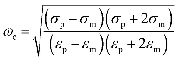 |
8 |
For low-permittivity particles in aqueous media (e.g. DI water), particles move towards the high field region at ω < ωc, referred to as positive DEP (pDEP), and towards the low field region at ω > ωc, referred to as negative DEP (nDEP). For particles in water, nDEP occurs when the permittivities of the system dominate due to the large ε = 79 of water as compared to that of nearly all other substances. The COF is given by
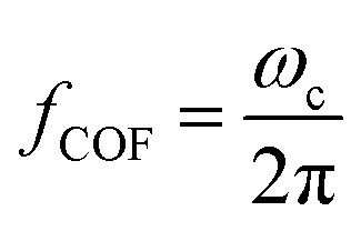 |
9 |
The key parameter, i.e. the electrical conductivity of a solid homogeneous PS bead, can be expressed as
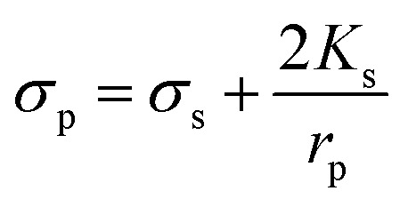 |
10 |
where Ks represents the surface conductance and rp is the radius of a particle.55Ks can be calculated as
 |
11 |
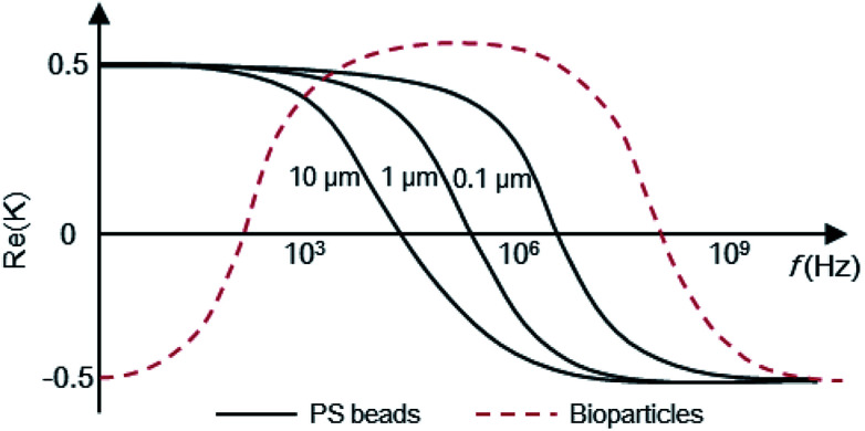
where fCOF is the crossover frequency and the DEP force is zero (Re(K) = 0). Therefore, the value of Ks has a linear relationship with the PS bead diameters if the permittivities of the suspending medium and PS beads are constant under fCOF. Surface conductance was calculated for the PS beads,56 and the Re(K) values of PS beads with different diameters were calculated, as shown in Fig. 3. If the 10 μm PS beads (εp = 2.6 and σp = 0.001 mS m−1) were suspended in DI water (εm = 79 and σm = 0.2 mS m−1), the frequency was on the order of 10 kHz for normal particle surface conductivities (about 1 nS). Thus, the 10 μm PS beads in DI water will distribute at the electrode gap under nDEP from 1 kHz to 100 MHz frequencies. However, other values (e.g. 1 or 0.1 μm) refer to the pDEP distributed at the electrode edge where the electric field is strongest. The conductance and DEP force are particularly sensitive to an increase in the surface charge,57 especially in the case of nanoparticles. When the concentration of the suspending medium increases (e.g., conductivity, σm, increases), Re(K) decreases and reverses its sign from positive to negative at low frequencies.58,59
Fig. 3. Re(K) with frequency on the PS beads.
The frequency is one of the important factors to ensure the polarizability of the PS beads. The voltage is applied to generate stable and sufficient DEP forces, further inducing particles within a certain electrode geometry. Several electro-physiological effects need to be considered while designing electrode architectural structures since DEP can directly affect the cell physiology.
2.3. Numerical analysis
One of major topics to be investigated in this field is numerical simulation or modelling, which can save resources, shorten the experimental period, and predict results. Simulation is used to identify an optimized geometry to enhance the capture of particles. With the rapid development of electronic computers, calculation softwares, such as COMSOL Multiphysics (COMSOL, Burlington, MA), computational fluid dynamics (CFD, ESI Group, France) and ANSYS Fluent (Fluent Inc, Lebanon, USA), based on various mathematical models have been widely used for the calculation of DEP forces. The distribution of a non-uniform electric field, the force of particles and the trajectory of motion are mainly analyzed in these software, as summarized in Table 2. To date, COMSOL is the most popularly used software in the calculation of both flow and electric fields due to the implementation of a finite element method (FEM) with adaptive meshing, error control and a variety of numerical solvers. COMSOL focuses on multiphysics modelling in electric fields, flow fields, thermal fields and particle trajectories, which are characterized by coupled calculation and tracer demonstration of the coupling FDEP, FDrag, FGra, FEo and thermal parameters. CFD and ANSYS FLUENT are good for calculating the FDEP and FDrag of particles in fluid. However, the problem associated with simulation is that most simulations only provide the distribution of the electric field and does not accurately predict the movement of particles. The difficulty lies in how to simulate the integrated force of particles in a complex fluid and track the movement of particles under combined forces at a controlled velocity.
Commercial software used for DEP simulation (“−” for nDEP and “+” for pDEP).
| Software | Scaling | Force | Parameter | 2D | 3D | Application | Ref. |
|---|---|---|---|---|---|---|---|
| COMSOL | 3–5 μm | +FDEP | Electric field | Cross-section | No | Improvement of collection | 63 |
| 1 μm | +FDEP, FDrag | Electric field | Cross-section | No | Collecting bacteria | 64 | |
| — | +FDEP, FDragFEo | Electric field; electroosmotic | Top-section | No | Optimizing the conditions | 65 | |
| — | +FDEP, FDrag, FEo | Electric field; particles trajectories; Joule heating | Top-section | Yes | Separation of healthy RBCs and RBCs infected by P. falciparum | 66 | |
| 9 μm | +FDEP | Electric field | Cross-section | No | Transporting of yeast | 67 | |
| CFD + ACE | 20–30 μm | +FDrag, | Flow field | Cross-section | No | Separation of cancer cell | 68 |
| 15 μm | −FDEP, FGra | Electric field | Cross-section | Yes | Collection PS beads and Si beads | 69 | |
| 10 μm | +FDEP, nDEP | Electric field | Cross-section | No | Manipulation of large groups of particles | 70 | |
| 10 μm | −FDEP, FDrag | Electric field | Cross-section; top-section | Yes | Trapping of PS beads | 71 | |
| 10 μm | −FDEP | Electric field; particles trajectories | Top-section | Yes | Trapping of PMMA NPs and cancer cells | 72 and 73 | |
| — | +FDEP | Electric field | Cross-section | Yes | Transporting of the oocyte and the sperm | 74 | |
| ANSYS FLUENT | 2–3 μm | +FDEP | Electric field | Cross-section | No | Trapping of erythrocyte | 75 |
| 9 μm | +FDEP | Electric field | Cross-section | Yes | Manipulation of yeast | 76 | |
| 4.8 μm | +FDEP | Electric field | Cross-section | No | Manipulation of PS beads and SnO2 nanobelts | 77 | |
| 1 μm | +FDEP | Electric field | Cross-section | Yes | Separation of PS beads and MWCNTs | 55 | |
| 0.08 μm | +FDEP, FDrag | Electric field | Cross-section | Yes | Manipulation of WO3 nanoparticles | 78 |
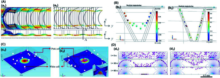
Although the general motion of a polarizable PS bead under the DEP force may be deduced from the electrical field distribution, the trajectory solution of the PS bead under moving DEP is not trivial. Cao et al. simulated the electric field distribution for different pitch values while keeping other geometrical parameters and the applied voltage identical to the values used in their experiments.60 Yan et al. tested the potential effect of voltage on the DEP-active hydrophoretic focusing and the PS beads passing through and obtained different patterns, as shown in Fig. 4A.61
Fig. 4. Particle trajectory in numerical analysis. (A) Particle trajectory at a voltage of 5 Vpp: (a1) inlet and (a2) outlet. Particles focused onto channel sidewalls under the effect of steric hindrance.61 (B) Trajectory of (b1) the PS beads in DI water and (b2) HeLa cells in a phosphate buffer saline (PBS) medium.62 (C) Simulation of the isolated cells in optoelectronic tweezers (OET): two randomly distributed cells were separated in 7 s under the (c1) pDEP and (c2) nDEP force.79 (D) Particle position at 0 s, 30 s and 60 s, and the magnitude contours of the electric fields. The gap of two bottom electrodes was 5 times the height of the dispersion chamber, and 15 μm PS beads were used for the simulation: (d1) U = 100 V and (d2) U = 150 V.69.
2.3.1. Hydrophoretic focusing of the 10 μm PS beads
PS beads smaller than half of the channel height in diameter61 were introduced at a 20 μL min−1 flow rate. They migrated back and forth inside the channel, as evidenced in (a1) in Fig. 4A, due to unsatisfied hydrophoretic ordering. They could not form hydrophoretic focusing without an electric field. However, the PS beads tended to focus on channel sidewalls when 5 Vpp voltage was applied at 1 MHz frequency (a2 in Fig. 4A). The beads were subjected to a nDEP force and were levitated to a higher position in the channel. This resulted in a greater intensive steric interaction between the particle and groove that led to hydrophoretic ordering. Regardless of their initial positions, the PS beads were focused onto each side of the channel. Das et al. performed numerical simulations in COMSOL to predict the distributions of a non-uniform electric field, DEP forces and particle trajectories, as shown in Fig. 4B.62 When a 10 Vpp voltage was applied at 1 MHz, the HeLa cells (pDEP) moved away from the center of the streamline (b2 of Fig. 4B), whereas the PS beads (nDEP) followed the central streamline along the channel length (b1 of Fig. 4B).
2.3.2. Dipolar cells
A 3D numeric model of cells was investigated with two different types of CM values in an optically induced DEP (ODEP) chip.79 The particle tracing for the fluid model in COMSOL was used to solve the numerical model of cells under the DEP force. The DEP force acting on the dipole of 11.8 μm cells subjected to a non-uniform electric field under 60 μm Gaussian-distributed beam spot was simulated in the enrichment process. The simplified structure and numeric model of the nucleated cell provided a theoretical basis for research on biosensors and natural life. The start point of microparticles in the optoelectric chip was scattered randomly. The direction of the DEP force, which depends on the size of the cells, permittivity, and conductivity of the suspending medium, changed upon the movement of the cells. The CM factor that referred to two types of cells was opposite if adjusting frequency on a function generator. As seen in (c1) in Fig. 4C, the pink and white cells were shown to simulate the optoelectronic tweezer (OET) chip due to their different CM values. The result of separation demonstrated that the optical spot captured the cells with a specific frequency. On the other hand, the white cells were repelled far away from the pink cells (c2 in Fig. 4C). The CM value of the pink and white cell was equal to 0.4 and −0.2, respectively, and the frequency f was 0.5 MHz. The assembly and isolation of cells were confirmed by the numerical model of cells, which maintained better consistency with the literature referring to experiments.
2.3.3. PS beads focusing in time-domain
In addition, the 15 μm PS bead focusing was further simulated using (d1) U = 100 V and (d2) U = 150 V, as shown in Fig. 4D.69 For both cases, the difference between the gravitational force and the vertical component of the DEP force was illustrated, where in the white region, e < 0, and in the grey region, e > 0. The three images show the position of the particles at t = 0 s, 30 s and 60 s.
The optimization of microfluidics numerical study offers the advantages such as requirement of less sample volume, faster analysis, precise fluid handling, and reduced biological and chemical wastes. The 3D structure design of electrode arrays will avoid the decentralization of a planar electric field and improve the sensitivity and separation efficiency of particles. The development of microfluidics also allows for the creation of better bio-devices for flow management and better understanding of the interaction between the hydrodynamic and electrokinetic forces.
3. Application
The applications of DEP covering from nanoscale to micro and macroscale materials, such as particles, wires, tubes and rods towards DNA, cells, and bacteria, are summarized in Table 3. Nano-scaled subjects include NPs, NTs, nanowires, nanorods, DNA and viruses. NPs have been extensively investigated by DEP manipulation, as shown in Fig. 2, due to their relative simplicity and repeatability. The evaluation of the performance and efficiency of NPs through the analysis and theoretical prediction of DEP can be regarded as a new research direction of DEP technology. In addition, NPs can be substantially and effectually used as nano-parts to fabricate functional and/or electrical biosensors.
DEP applications in different scales.
| Nano-scale | Micro-scale | Milli-scale |
|---|---|---|
| Nanoparticles (PS,19 Au; Ag,85 Pd,86 CdTe,87 Silica,88 PMMA,72 tungsten trioxide (WO3)78 and ZnO89) | Non-bioparticles (PS,90 Janus; Silica,91 and melamine particle92) | Algae93 |
| Nanowires (SiC; ZnO,21,110 CuO,111 Pt,112 and Fe2O3 113) | Cells (yeast cell,94 RBC, cancer cell, fibroblast cell,95 osteosarcoma cell, Neural,96 human leukemia cell,97,98 circulating tumor cells,98M. smegmatis,99 and B lymphoma cell100) | Clay107 |
| Carbon-based nanomaterials (carbon nanotubes20 and graphene114) | Bacteria (E. coli,58,59Staphylococcus epidermidis,101Salmonella, Listeria monocytogenes,102K. pneumonia,103 and Lactobacillus104,105) | Silicone108 |
| Nanorods (ZnO22,115) | Single-stranded DNA106 | Minerals109 |
| Nanobelts (SnO2 116 and ZnO117) | ||
| DNA23,118 | ||
| Virus24,119 | ||
| Bacteriophage120 |
DEP has been a useful tool for the study of different cells since its development. In 1966, yeast cells were first applied in the DEP separation of living and dead cells.80 After this, DEP equipment has been mainly used in the enrichment and isolation of yeast cells. Since 1982, when human malignant melanocytes were first successfully arranged by DEP,81 DEP has been widely used in the manipulation of tumor cells. In 1984, the blood cells obtained from patients suffering from sickle cell anemia were first used to distinguish normal red blood cells and sickle cells by DEP.82 Subsequently, the study of mammalian cells (i.e. tumor cells83 and fibroblasts84) was applied in DEP research. In 1989, Micrococcus lysodeikticus was first investigated by optical DEP measurements.121 Subsequently, bacteria began to be introduced into the DEP application. Since 1994, with the rapid development of micro-electromechanical systems, DEP devices have exhibited greater precision and can be used in the manipulation of smaller particles such as DNA122 and viruses.123 Cells obtained from various species possessing dissimilar particles experience different DEP forces. Furthermore, the same type of particles present irregular spheres and homogeneity due to their different growth states. Moreover, it is difficult to obtain accurate electrical conductivity and dielectric constants; this leads to some differences between the simulation and actual results. Therefore, PS beads with a standardized size, dielectric constant and conductivity can be used to more accurately simulate the force and motion of particles.
DEP forces are versatile and can be tuned simply by changing the frequencies or by fabricating electrodes with different shapes in an array to achieve DEP trapping. This approach plays a vital role in biosensors, diagnostics and medical research. Particles should be first trapped in the detection region. The location has an important impact on the accuracy of the measurement results. PS beads are often used to verify the feasibility of devices with biological particles because they are comparable in size. As has been discussed in the previous section, trapping and separation of PS beads are major issues in DEP manipulation.
3.1. Trapping of single-sized PS beads
3.1.1. Micro-scaled PS beads
DEP manipulation of PS beads is primarily carried out for trapping various scaled beads in a suspending medium by an electric field. The DEP voltages applied are significantly lowered from the thousands to tens scale; however, the electric field density is sufficient for particle manipulation. Micro-scaled beads are typical and fundamental subjects for the investigation of trapping conditions. Recently, nano-scaled and functionalized PS beads were specially applied for affinity biosensors that exploited antibody–antigen interactions.
(1). Accumulated crystals
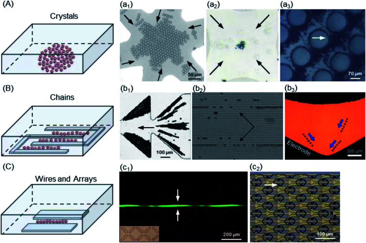
Electrode geometry is an important factor to ensure that stable and sufficient DEP forces are applied to induce micro-scaled PS beads. A number of microelectrode geometries were designed for specific research purposes. In previous studies, DEP-manipulated PS beads were used in solution to fabricate many structures including crystals, chains, wires and arrays, as summarized in Table 4.
Structures fabricated by trapping of micro-scaled PS beads.
| Structures (efficiency) | Theory | Scale (μm) | Medium (mS m−1) | Electric field | Ref. |
|---|---|---|---|---|---|
| Accumulated crystals (17–341%) | nDEP | 10 | DI water | 2–6 Vpp, 1 MHz | 124 |
| AC-DEP | 2 | KCl (1.42) | 10 Vpp, 0.1–10 MHz | 126 | |
| DEP | 10, 25, 45 | KCl (0.7–15.9) | 4–12.5 Vpp, 1 kHz to 1 MHz | 132 | |
| DEP | 10 | DI water (1.7); NaCl (8.4) | 10 Vpp, 100 Hz to 5 MHz | 125 | |
| AC-DEP | 10 | — | 21 Vpp, 50 kHz | 133 | |
| AC-DEP | 1 | — | 12 Vpp, 1–4 MHz | 127 | |
| DC-iDEP | 6 | DI water | 200–500 V | 130 | |
| ODEP | 2.9 | KCl | 555–885 VRMS, 30–100 kHz | 131 | |
| Lined chains (95–100%) | twDEP | 10 | DI water (1) | 2 Vpp, 1 MHz | 56 |
| AC-DEP | 4.3 | DI water (10) | 5 Vpp, 100 Hz to 10 MHz | 34 | |
| AC-DEP | 10 | DI water (0.2) | 5 Vpp, 1 MHz | 63 | |
| ACEO-DEP | 0.5, 2, 3 | DI water | 2–5 Vpp, 0.1–500 kHz | 134 | |
| pDEP | 1, 2, 5, 10 | DI water (152/158) | 2–10 V, 500 Hz | 135 | |
| Acoustic-DEP | 10 | DI water (0.001) | 16 Vpp, 5 MHz | 70 | |
| DC-iDEP | 10 | PBS | 100–850 V | 136 | |
| DEP | 10 | DI water (20) | 10 V, 500 kHz | 137 | |
| iDEP | 18, 24.9 | DI water (0.6) | 15–300 V, 20 kHz | 138 | |
| CP-DEP | 5, 10 | PBS (1–250) | 141 VRMS, 0.5–500 kHz | 139 | |
| Wires | cDEP | 10 | DI water (0.5) | 95–160 Vpp, 100 kHz to 1 MHz | 140 |
| IM-DEP | 6 | NaCl | 2 Vpp, 184 Hz | 141 | |
| AC-DEP | 6, 10 | (20) | 2–10 V, 1 MHz | 142 | |
| Arrays (63%) | AC-DEP | 10 | Tris–acetate–EDTA (60) | 7 Vpp, 1 MHz | 143 |
The crystal was the earliest structure of PS beads trapped by DEP, which depended on electrode shapes including interdigitated, quadrupole, probe, and circular post, as shown in Fig. 5A. At low field-strengths, chaining structures are barely generated, whereas crystal formation is initiated at high field-strengths. Kim124et al. used nDEP to immobilize a single-crystal domain on a glass substrate without losing its crystallinity and resorted to a larger gravitation force of 10 μm PS beads to allow the formation of defect-free single-crystal domains. A quadrupole microelectrode dedicated for trapping single cells was designed and constructed on a multilayer LOC structure called the sandwiched insulator with a back contact (SIBC) biochip platform, in which 22% Ishikawa cancer cells and 17% 10 μm PS beads were successfully trapped.125 Haapalainen and Mäkynen presented a microfluidic DEP platform with a hyperbolic quadrupole electrode geometry, which was implemented for particle characterization.126 The electrodes of the implemented platform were made of ITO to achieve full transparency and consequently, better view of the particle motion using common transluminescence microscopy. Freedman et al. tracked the 1 μm PS beads used for DNA sensing to demonstrate the distinct forces observed for both DEP and electrothermal flow (ETF).127 Mohammadi's group studied a geometrical relationship to optimize the efficient geometry of the post array distribution in insulator-based DEP (iDEP)128 (also known as contactless DEP (cDEP)129,130). They presented microfilters, with a similar footprint and channel thickness, that maximized the trapping condition while minimizing the required voltage. The obtained results indicated that a post radius of 40 μm, larger than the transversal distance between posts, could enhance the trapping, which supported and extended a master scaling for the field strength efficiency from 56% to 341%. McMullan et al. reported the formation and kinetics of DEP-directed self-assembled ordered structures via a combination of microscopy and light scattering over an extended range of particle sizes, electrokinetic properties, and frequencies required to induce particle chaining.131 The high field applied in cDEP and ODEP increases the trapping efficiency of the PS beads. However, these techniques have some drawbacks, especially for bioparticles. Implementation of a high electric field has some disadvantages. The complicated fabrication procedures reduce the layer lifetime. Joule heating and an increase in temperature were caused by a highly conductive biological fluid and high electric field intensity (e.g., 500 V). Additionally, manipulation of cells is difficult with iDEP and ODEP due to their collecting patterns and devices. The trapping of PS beads can reach high efficiency by iDEP and ODEP; however, this is not the case for bioparticles, which are still challenging.
Fig. 5. Trapping modes of the micro-scaled PS beads. (A) Structure of crystals: (a1) 10 μm PS beads,124 (a2) 2 μm PS beads,126 and (a3) 2 μm PS beads by iDEP.130. (B) Structure of chains: (b1) 10 μm PS beads in the ratchet microchannel,136 (b2) 10 μm PS beads in a combined acoustic DEP system,70 and (b3) 18 μm PS beads in the curved microchannel.138 (C) (c1) Structure of wires: 10 μm PS beads in X-patterned insulating structures.140 (c2) Structure of arrays: 10 μm PS beads in the cello-type mechanical trap.132.
(2). Lined chains
One of the interesting structures of the PS beads trapped is chains, located in the electrode gaps by nDEP and the interaction force of beads, as shown in Fig. 5B. An interdigitated electrode is the most common geometry used. Cui and Morgan presented a generic twDEP separation system to handle a complete particle and fractionate system.56 Chen et al. have demonstrated that the levitation height of a specific PS bead strongly depends on the combined contributions of parameters such as the frequency of the electric field, dielectric properties of PS beads and suspension medium.34 Ravula et al. discussed the modeling, fabrication and characterization of a platform that combined acoustic forces and AC DEP, in which 10 μm PS beads were further focused into single file bead streams (b2 of Fig. 5).70 Kale et al. presented an experimental study of particle trapping in an asymmetric ratchet microchannel under DC-biased AC electric fields.136 The DC/AC DEP accumulation of PS beads in the first pair of ratchets and the DC electrokinetic shifting of particles into the second and subsequent ratchets were studied, which depended on the moving direction of beads with respect to the asymmetric ratchets. The PS beads were trapped into triangular zones in all, but later they were trapped in the first pair of ratchets for both forward and backward motions. The trapping efficiency was 100% in this ratchet microchannel. Allen et al. demonstrated both pDEP and nDEP using silver-coated hollow glass spheres and PS beads, respectively, with isomotive DEP (isoDEP) devices.138 Both AC/DC electric fields could trap the PS beads by nDEP with a trapping efficiency of approximately 95–100%.
(3). Wires and arrays
Another similar interesting structure is wires. The PS beads are placed in a planer-electrode gap by nDEP, as shown in Fig. 5C. Jen's group examined the feasibility of using cDEP in an iDEP microdevice to effectively trap 10 μm and 13 μm PS beads (c1 of Fig. 5C).140 Su and Voldman developed an automated system and presented characterization of the method using 6 μm and 10 μm PS beads and HL-60 cells as well as its application to rapidly discriminate neutrophils with different activation states.144 Carboxyl-modified PS beads were used for modelling validation and calibration. The system could accumulate large datasets for different cell types for electrical studies of cells and applications of label-free DEP separation. Guler et al. utilized 3D microwire electrodes to detect 6 μm PS beads and erythrocytes using an LCR meter without any additional electronics (e.g., lock-in amplifiers and custom-made electronic circuitries).141 This yielded very high sensitivity as compared to the case of conventional coplanar electrodes, which require several repetitive cleanroom processes for the fabrication of micro-electrodes. This provided a method for integrating electrodes into a standard soft lithography process.
A set of electrode arrays accurately fabricated by MEMS technology was used for trapping the PS beads by pDEP, as shown in Fig. 5C. The reversibility of the guiding and trapping effectiveness was predicted using the 1 μm, 2 μm and 10 μm PS beads.143,145 The PS bead flow was up to roughly 200 μm s−1 after approximately 2 min as the voltage was changed to 7 Vpp, and 98% of the PS beads were released when the voltage applied was turned off. An iDEP study clearly indicated the effects of particle size and shape on DEP trapping by employing 1 μm and 2 μm PS beads and E. coli cells.146 The PS bead size and flow speed have a significant effect on the magnitude, location, and shape of the DEP trapping regions, which are defined by the DEP isovelocity lines and EK isovelocity lines (c2 of Fig. 5C). Both AC/DC electric fields can trap the PS beads by pDEP with an approximately 63% efficiency.
DC-DEP enables highest trapping efficiency for PS beads due to its high electric field. However, bioparticles will be overcooked by its high electric field. Although DEP manipulation of particles and molecules has been extensively performed using microelectrodes or sharp tips, some hurdles still exist such as heat and bubble generation and unwanted surface reactions due to high voltages. Additionally, the DEP devices used for micro-particles require a special electrode design and some specific instruments. Especially, plenty data needs to be obtained to achieve statistically reliable results; however, this will consume a lot of time.
3.1.2. Nano-scaled PS beads
Considering that many important biological subjects, such as protein molecules and viruses, are on the order of 10 nm in size, it is desirable to maximize the trapping efficiency and overcome the Brownian motion of particles for the DEP electrodes with equally small gap sizes. Smaller gaps can create stronger electric field gradients to reduce the voltages applied for DEP trapping, avoiding unwanted surface electro–chemical reactions, bubble formation, and heat generation, all of which are major challenges for broader DEP applications. The validation and calibration of research on nano-scaled PS beads are summarized in Table 5, and the experimental evidence of manipulation is shown in Fig. 6.
Trapping of the nano-scaled PS beads.
| Type | Scale (μm) | Suspending medium (mS m−1) | Electric field | Time | Reference |
|---|---|---|---|---|---|
| CE-DEP | 0.39; 0.46; 0.59; 0.62 | KOH and MOPS (11–20) | 2 Vpp; 100 kHz to 2 MHz | — | 54 |
| SAW-DEP | 0.19 | KCl (0.2–1) | 7 VRMS; 10 Hz to 10 MHz | 9 s | 153 |
| DC-iDEP | 0.59 | PBS (47) | 100–850 V; 1 kHz | 4 s | 40 |
| DC-iDEP | 1 | DI water (0.2); K2HPO4 (10) | 100–1500 V | 30 s | 148 |
| IM-DEP | 0.78 | Tris–EDTA (20) | 0.2–1.0 V; 2–10 MHz | 1 s | 149 |
| AC-DEP | 0.03; 0.19 | DI water (0.4); PBS (18.2) | 0.2–1.5 V; 100 kHz to 10 MHz | 60 s | 36 |
| DEP | 0.74 | PBS (10) | 500–2000 kHz | 5 s | 150 |
| AFM-DEP | 0.2 | DI water | 5 Vpp; 10 kHz | 10 s | 151 |
| AFM-DEP | 0.02 | DI water, PBS and Tris–EDTA (10–490) | 120–150 V; 1 MHz | 60 s | 152 |
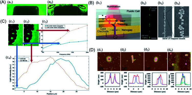
Fig. 6. Examples of the trapping of the nano-scaled PS beads. (A) Particle streak images in the microchannel constriction region of an iDEP device under various DC-biased AC (fixed at 1 kHz) voltages: (a1) 600 V DC and (a2) 20 V DC/580 V AC. The arrowed loops in the 20 V DC/580 V AC case indicate the directions of electrothermal flow circulations.148 (B) Nanogapped DEP electrode: (b1) schematic of an array of nanogapped electrodes, each of which were individually addressable for DEP trapping. (b2) The beads were attracted to the gap in pDEP. (b3) and (b4) SEM images of trapped 190 nm PS beads along the nanogap at different magnifications. Scale bars: 20 μm, 2 μm, and 400 nm.36 (C) Quantification of biotin-functionalized PS beads: (c1) and (c2) visible darker regions and bright layer edges were electrodes formed by the accumulation of PS beads, respectively. (c3) nDEP spectrum of biotin-functionalized PS beads with 0% and 0.8% of biotin conjugation. (c4) Light intensity as a function of the distance from the electrode edge. The red scale bar indicates 50 μm.150 (D) Different assembled nanostructures, 2D AFM images and AFM scanned profiles: (d1) basin-shaped, (d2) linear, (d3) ellipsoidal, and (d4) nanodots.151.
(1). Joule heating-aided
Lewpiriyawong et al. demonstrated that a DC–AC offset reduced the Joule heating by lowering the necessary voltage; however, insights into temperature were not provided.35 Kale's group utilized a 3D numerical model to study Joule heating and its effects on the coupled transport of heat, where 0.59 μm fluorescent and 3 μm PS beads were applied in an iDEP device with a rectangular constriction microchannel.40,147 Buffer conductivity variations should be considered to determine the magnitude of heating effects by both simulations and experiments.148 The nDEP behaviour of inert 1 μm PS beads was observed in the experiments under the reported conditions, and the particle-trapping capacity of the device was observed to decrease due to heating of the buffer inside the microchannel by a DC voltage, as shown in Fig. 6A.
(2). Nanofabrication-aided
Tanaka et al. reported the use of DEP to manipulate single-carboxylated PS beads passing through the electrode-embedded pore structures. The variation in the tunnelling current was expected to diminish by controlling the molecular conformations residing in the electrode gap through the DEP mechanism.149 Barik et al. have demonstrated an ultralow-power DEP using nanogap electrodes fabricated via atomic layer lithography to trap the 30 nm PS beads, which can potentially enable high-density integration on a chip and portable biosensing, as shown in Fig. 6B.36
(3). Affinity cytochemistry-aided
Kirmani et al. reported a DEP spectroscopy label-free immunoassay for rare analyte quantification in biological samples with the capability to detect and quantify about 850 avidin molecules attached to biotin-functionalized PS beads, as shown in Fig. 6C.150 The electrodes were visible in darker regions, and a bright layer on their edges was formed by the accumulation of PS beads. Moreover, improved automated quantitative measurement of DEP was achieved through image processing, and DEP spectrum curves were obtained for two different concentrations of avidin–biotin conjugates over a range of frequencies.
(4). AFM-aided
Zhou's group presented a novel method of applying AFM tip-induced DEP (AFM-DEP) for the manipulation of 200 nm PS beads, which were assembled into various nanostructures, including lines, ellipsoids and arrays of dots, as shown in Fig. 6D.151 Both the size and shape of the assembled structures were controllable by various experimental parameters; this demonstrated the potential of AFM-DEP for applications in the fabrication of nanostructures and arrays, assembly of nanodevices, and non-destructive manipulation of biological nanoparticles. Recently, a coaxial AFM nano-probe device has been studied for DEP trapping of DNA molecules in Tris–EDTA and PBS buffers.152 The 20 nm PS beads were concentrated in the high-field region of the AFM probe end due to the pDEP force in low-conductive solution environments, and they experienced nDEP force in a high-conductive buffer solution.
The microelectrode geometries used to manipulate nanoparticles often require complex and expensive multiple layer fabrication. Moreover, for nanoparticles, some of the DEP devices require precision fabrication (i.e. atomic layer lithography), and the fabrication procedures are not suitable for mass production.
3.1.3. Functionalized PS beads
As abovementioned, PS beads have stable physical and chemical properties and are widely used in microfluidics devices via DEP. When the PS beads are coated with carboxylate groups, the surface potential of the negative charges will increase. When contacted with an amine group (a positive charge), they may create an electrostatic bond and form a larger macromolecule. The net charges not only affect the polarization strength of the suspending medium, but also influence the electric field force.154 The carboxyl-functionalized PS beads were covalently coupled to ethanolamine using a single-step reaction, especially rendering the beads uncharged and hydrophilic. The ethanol layer on the particle surface acts to reduce the hydrophobic nature of the PS beads. Spherical PS beads with surface isotropic chemical groups have been widely investigated via their structure–property relationship and self-assembly behaviour. Protein–protein interactions and bacterial targeting or immobilization can be extended to the detection of rare biomarkers using PS beads functionalized with appropriate antibodies. These PS beads can be further fabricated as anisotropic particles such as Janus particles (JPs), having two distinct surface chemical compositions or properties on two sides. JPs are applied in a wide variety of novel material properties as well as intriguing interparticle interactions.155 The trapping of functionalized PS beads is summarized in Table 6.
Trapping of functionalized PS beads.
| DEP type | Scale (μm) | Suspending medium (mS m−1) | Electric field | Time | Reference |
|---|---|---|---|---|---|
| nDEP | Protein-6.7; IgG-7.4 | PBS; NaOH (200) | 10–20 Vpp; 10 MHz | 10 min | 156 |
| ICEP-DEP | 3.8, JP-3.8 | NaCl (0.7–116) | 6 V; 40 kHz | 17 min | 90 |
| ODEP | 10; 15 | DI water (2.14), NaCl (95/106) | 5–7.5 Vpp; 5 kHz to 1 MHz | 157 | |
| SERS-DEP | AuNPs-1 | EDC, PBS | — | 2 h | 158 |
| DFS-DEP | Func-15 | DI water (0.64) | 0–2 Vpp; 10–100 Hz | 0.04 s | 159 |
| Raman-DEP | Flu-3.3 | PBS (4) | 350 Vrms; 100 Hz | 25 s | 160 |
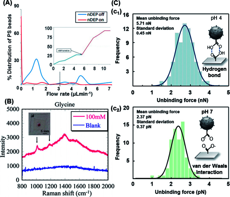
Javanmard's group experimentally tested a novel microfluidic platform that demonstrated the ability of nDEP to elute specifically bound beads with a switch-like behavior, as shown in Fig. 7A.156 nDEP in conjunction with shear force was used at an optimal NaOH concentration to illustrate the DEP responses in a singleplex assay. With nDEP off, the flow rate was increased to 0.95 μL min−1, and the majority (70%) of the beads was removed. This platform offers the potential for performing a bead-based (6.7 μm protein-G-coated PS and 7.4 μm goat IgG-coated PS) multiplexed assay in various regions of a single channel. Different antibodies were immobilized to target the corresponding antigens. The DEP characteristics of non-functionalized and carboxyl-functionalized 5 μm PS beads were investigated in solutions with different conductivities by associating the measured crossover frequencies with a theoretical DEP model. In the experiments, specific (streptavidin–biotin) and nonspecific (NH3+–biotin) interactions and two ligand–receptor interactions (streptavidin–biotin and avidin–biotin) were simultaneously evaluated, and different individual bond-rupture forces associated with the measured values were clearly determined.157
Fig. 7. Trapping modes of the functionalized PS beads. (A) Percentage distribution and detachment time profile of the detached beads in 0.2 M NaOH. Upon turning the nDEP on, about 80% of the beads detached.156 (B) Characteristic Raman spectra of glycine immobilized on AuNP-decorated PS beads with linked bridges via peptide coupling and the blank (ultrapure water with AuNP-decorated 20 nm PS beads and no analyte).158 (C) The measured unbinding (rupture) forces of 15 μm PS beads: (c1) hydrogen bond and (c2) van der Waals interaction.159.
Peptide coupling on AuNP-decorated 1 μm PS beads by DEP enabled the surface-enhanced Raman scattering (SERS) detection of glycine. DEP-enabled immobilization of higher-order nanostructures for Raman spectroscopy of a specific analyte was demonstrated by linker bridges on fabricated AuNP-decorated PS beads, as shown in Fig. 7B.158,161 A similar method was also demonstrated by an automated DEP tweezer-based force spectroscopy system to examine the intermolecular weak binding interactions.159 In the experiment, according to the numerical expectation, the carboxyl-terminated 15 μm PS beads were arranged through the center of the IDT electrodes covered by silicon dioxide with an nDEP force, and then, the rupture event of the arranged particles occurred since the vertical nDEP force was increased by increasing the applied AC voltage. The rupture forces of the weak binding interactions (e.g., van der Waals interaction and hydrogen bond) were measured by the developed system and compared with the previous results, as shown in Fig. 7C. Glycine was bound with the PS beads through peptide coupling induced via EDC. More recently, Hanson and Vargis presented an alternative method to fabricate a cDEP device, allowing higher operating voltages, improved replication, and the opportunity for analysis using Raman spectroscopy.160 The cDEP devices were capable of simultaneously trapping and analyzing the 3.3 μm PS beads via Raman spectroscopy; however, their fabrication, replication, and reuse were difficult. In addition, their operating parameters were limited by the dielectric breakdown of polydimethylsiloxane (PDMS).162 However, cDEP is still a powerful label-free tool to sort biological samples without tags, fluorescent markers, or specific DNA sequences for subsequent identification. It avoids common problems associated with DEP (e.g., electrode fouling and electrolysis).
Functionalized PS beads with antibodies can be applied in the detection and quantification of rare analytes for the prevention and treatment of diseases such as cancer and myocardial infarction. In addition, additional expertise and equipment are required to characterize the functionalization performance of functional particles. Surface micromachining techniques allow electrodes to be very close to each other (e.g., tens of micrometers).
3.2. Separation of multiple-sized PS beads
In addition to trapping, the DEP force is very suitable for size fractionation, which can improve the screening performance of varied sized particles when microelectrode arrays are used or when it is combined with other devices (e.g. microfluidic platforms). The size of the PS beads is similar to that of cells such as bacterial cells (0.8–2 μm), red blood cells (7–8 μm), liver cells (20–30 μm) and many cancer cells (10–30 μm). Separation of multiple-sized PS beads can provide prediction for PS beads and mixed particles.
3.2.1. Characterization of multiple-sized PS beads
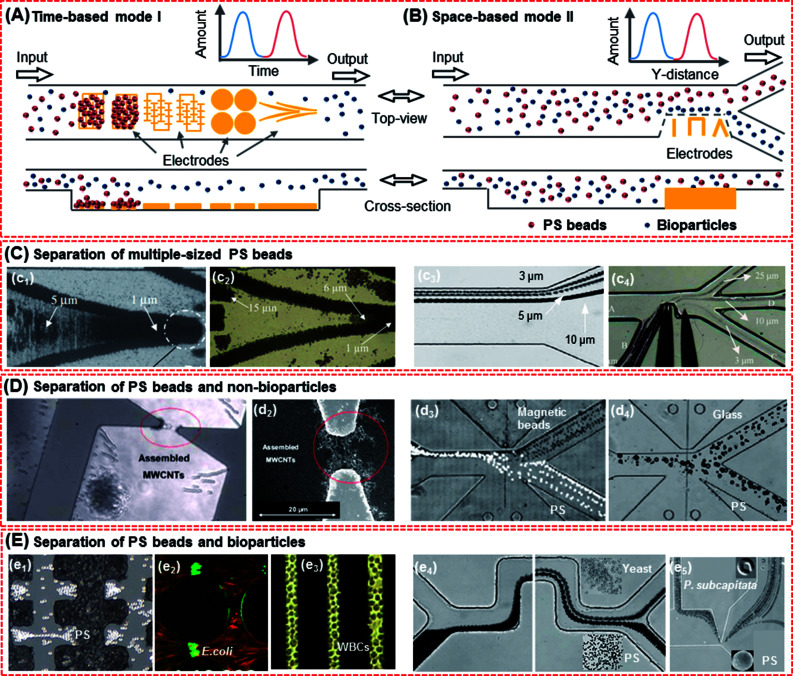
Levitation is vital for the separation of multiple-sized PS beads. The levitation height results from the resultant force, such as nDEP and gravity, acting on particles in a vertical direction. Efficient positioning of outlets for different particles depends on the accurate prediction of the levitation height of particles. The levitation height is dependent on the CM factor, where larger PS beads are deflected more than smaller particles. Multiple-sized PS beads in suspensions are consequently separated into different transverse positions (or level heights) by size as they flow down into a microfluidic device along its length. In addition, the surface conductivity of PS beads is inversely proportional to the radius of the PS beads. The surface conductivity is significantly larger than bulk conductivity. Therefore, the CM factor of the 1 μm beads is smaller than that of the 10 μm beads. The levitation height of 1 μm beads is smaller than that of the 10 μm beads. As a result, 1 μm beads are dragged to the electrode edges due to their lower levitation height. Tunable multiplex separation of multiple-sized PS beads is classified into two modes: time-based separation mode I (Fig. 8A) and space-based separation mode II (Fig. 8B), as detailed in Table 7.
Fig. 8. Separation of the PS beads and mixed particles. (A) Time-based mode I, with different electrodes acting as sample plugs, which could lead beads into the separation region and split into two species or more. The species were separated in time. (B) Space-based mode II, in which a sample was continuously led in a separation region and species were spatially separated. (C) Separation of multiple-sized PS beads. Mode I:18 (c1) 1 and 5 μm PS beads and (c2) 1, 6 and 15 μm PS beads. Mode II: (c3) 3, 5 and 10 μm PS beads169 and (c4) 3, 10 and 25 μm PS beads.168 (D) Separation of PS beads and non-bioparticles. Mode I: (d1 and d2) 1 μm PS beads with SWCNTs.55 Mode II: (d3) 5 μm PS beads and magnetic beads173 and (d4) 15 μm PS beads and 14 μm sliver-coated hollow glass beads.173 (E) Separation of PS beads and bioparticles. Mode I: (e1) 7 μm PS beads and yeast cells,174 (e2) carboxylate-modified PS beads (red) and live E. coli (green),145 (e3) PS beads and K562 cells.41 Mode II: (e4) 3 μm PS particles and yeast cells172 and (e5) 5 μm PS beads and algae.93.
The separation of multiple-sized PS beads.
| Mode | Type of DEP | Scale (μm) | Suspending medium (mS m−1) | Electric field | Ref. |
|---|---|---|---|---|---|
| I | AC-DEP | 1/5; 1/6/15 | DI water (0.2) | 30 V, 10 kHz to 20 MHz | 18 |
| AC-DEP | PS: 10/15; streptavidin-terminated PS: 10/12/15 | DI water | 5–7.5 V; 5–1000 kHz | 157 | |
| AC-DEP | 6/10 | KCl (1.8) | 300–3000 Hz | 38 | |
| AC-DEP | PS: 4; Dynal magnetic beads; goat antimouse conjugated beads | PBS | 6 V; 40 kHz | 163 | |
| DC-DEP | 0.1/0.2/0.5/1 | NaCl (3.5) | DC: 1300 V; AC: 2800–3600 Vpp; 1 kHz | 164 | |
| AC-DEP | 3/10 | DI water | 10 V, 0–1.5 MHz | 165 | |
| II | DC-DEP | 1.97/4.84 | NaCl; PBS | 100 V | 166 |
| DC/AC-DEP | 0.02/0.1 | PBS | DC: 5–50 V; AC: 600 Hz | 167 | |
| AC-DEP | 3/10/25 | DI water (0.15) | 120–150 V, 1 MHz | 168 | |
| DC-DEP | 3/5/10 | PBS | 600–1320 V | 169 | |
| DEP | 11/25/45 | Milli-Q water | 200 V, 200 kHz | 170 | |
| DEP | 4/5/6 | DI water | 4–12.5 V, 1 kHz | 39 | |
| DC-DEP | PS: 3/5; Janus: 3/5 | −50 | 120–290 V | 171 |
3.2.2. Multiple-sized PS beads in mode I
In the time-based separation mode I, PS beads are trapped due to frequency changes. The DEP electrode architectures act as sample trappers, inducing the PS beads to the separation regions by pDEP. Multiple-sized PS beads split into two species or more, as shown in Table 7 and Fig. 8C. The species are thus separated in time, and the distance in the y direction will continue to respectively separate and accumulate various PS beads. Khoshmanesh et al. utilized curved microelectrodes to separate 1, 6 and 15 μm PS beads at the frequencies of 100 kHz, 200 kHz, and 20 MHz, respectively, as shown in Fig. 8(c1 and c2).18 Lin et al. utilized a circular micro-electrode array to separate the PS beads.38 Herein, 83% of 10 μm beads were trapped in a circular band at a radius ranging from 100 to 120 μm, and 91% of the 6 μm beads were located between from 380 and 400 μm radii. More recently, Zhang et al. fabricated a DEP-enhanced microfluidic impedance biosensor for pathogen detection.163 Pathogens were isolated from samples using PS immune-beads, followed by DEP-assisted pathogen capture at boron-doped ultrananocrystalline diamond (BD-UNCD) microelectrodes and quantification of the capture using impedance spectroscopy. The carboxylate-modified beads with poly(ethylene glycol) (PEG) provided the highest capture efficiency (65%) and selectivity (95%) in isolating live E. coli O157 : H7. Higher specificity was achieved upon the addition of PEG to the antibody-functionalized bead surface, the highest specificity was achieved with the epoxy-sulfate beads (85–86%), followed by carboxylate-modified beads (76–78%) and aldehyde-sulfate beads (74–76%). Romero-Creel et al. demonstrated how the PS beads that were of the same size and shape and made from the same substrate material could have different DEP behaviors as a result of their distinct surface charge magnitudes.164 The red-carboxyl beads in the mixture were considered to have a higher surface charge than the green-amine beads. Another DEP-based PS bead sensing system was recently developed by Yahya for separating 3 and 10 μm PS beads in an array of tapered square electrodes.165
3.2.3. Multiple-sized PS beads in mode II
The other separation mode is the space-based mode II, which can synchronously separate PS beads with various sizes by nDEP at the microelectrodes with shapes of sharp tips, triangular, planar and wires flowing to different outlets at the same time, as shown in Table 7 and Fig. 8C. Previously, Kralj et al. used DEP to separate a mixture of 4, 5 and 6 μm PS beads, with the flow rate and voltage parameters from the model used as initial estimates for experiments.39 Zhu et al. demonstrated the continuous-flow electrokinetic separation of 1 and 5 μm PS beads in a serpentine microchannel through curvature-induced DEP.172 Sun et al. separated 1.97 and 4.84 μm PS beads through the integration of a metallic oxide semiconductor field-effect transistor (MOSFET)-based microfluidic Coulter counter with a DC-DEP cell sorter.166 Viefhues et al. presented a microfluidic device capable of performing two tasks: it could be operated in either mixing or demixing mode with 20 and 100 nm PS beads.167 These parameters could be adapted in real time, and the continuous separation and mixing efficiency of 85–100% was achieved. A similar method was demonstrated by separating both a binary and ternary mixture of 5 and 10 μm PS beads and a ternary separation of 3, 5 and 10 μm PS beads by intrinsic properties (e.g., size and surface charge) in a T-shaped microchannel, as shown in Fig. 8(c3).169 Tao et al.168 used acupuncture needle electrodes to facilitate the integration of working electrodes in a DEP system. Multiple-sized PS beads (3, 10 and 25 μm) were separated and moved to different outlets by DEP, and a purity efficiency of over 90% for the 10 μm PS beads was achieved, as shown in Fig. 8(c4). Wang et al. developed a sheath flow-assisted DEP field-flow separator with a tailored arrangement of cylindrical IDT electrodes and observed the size-dependent trajectories of dispersed particles.170 Using a voltage of 200 V at a frequency of 200 kHz, 11, 25 and 45 μm PS beads were levitated to different heights along the channel length due to the nDEP forces.
The DEP separation of multiple-sized PS beads only depends on the surface conductivity of these beads. For particles with different sizes, separation by DEP based on their electrical properties (e.g. conductivity) and suspending medium requires specific integrated and accurate electrodes arrays for improved separation efficiency. The limits (e.g., design limitations and geometric tolerances due to the fabrication process) and stability of the separation modes play a major role in state-of-the-art applications with complex mixtures. The time-based mode I seems to be more suitable for separating particles of different sizes than model II. However, for particles of similar sizes, the separation by DEP based on their electrical properties and suspending medium requires discrete processes and becomes challenging.
3.3. Separation of the PS beads and non-bioparticles
Separation of the PS beads and other particles (organic and inorganic) has been discussed as follows. For inorganic particles in mode I, Zhang and Khoshmanesh presented a platform for separating 1 μm PS beads and MWCNTs (20–50 nm in diameter and 0.5–2 μm in length) according to their dielectric response to alternating electric fields at specific frequencies (about 150 kHz), as shown in (d1–d2) of Fig. 8D.55 More recently, Zhao et al. presented a nano-orifice-based microfluidic device using a DC-DEP method to continuously separate different types of micro and nanoparticles, which included 5.2 μm magnetic-coated PS beads, 7 μm fluorescent PS beads, 14 μm sliver-coated hollow glass beads and 15 μm plain PS beads, with similar sizes by their different electric conductivities in a pressure-driven flow.173 They also numerically demonstrated the separation of 5 μm Janus particles and homogeneous PS beads and the separation of 3 and 5 μm Janus particles using DC-DEP in the mode II, as shown in Fig. 8(d3).171
3.4. Separation of the PS beads and bioparticles
The separation of bioparticles from a complex mixture is important for numerous applications in cell sorting, infection diagnosis, food safety, and enrichment of particle populations for drug development. Separation is accomplished by the intrinsic physical properties of a cell type, which defines a specific finger print that can be expressed as an induced force that drives the separation of cells in complex mixtures.
3.4.1. Characterization of bioparticles
Commercialized cell sorter systems, such as fluorescence-activated cell sorting (FACS) and cell labeling, require tedious cell preparation, whereas DEP is a simple and cost-effective technique that can be implemented in this area. DEP-based cell separation has significant promise for the separation of cells from heterogeneous mixtures based on their electrical properties and is used in cell purification, such as in the purification of human promyelocytic leukaemia cells (HL-60)38 and Chinese hamster ovary (CHO) cells,175 or target cell isolation. The DEP technique offers advantageous identification and differentiation of target cells as compared to the conventional FACS approach. In the DEP rapid detection, various target biological particles (such as antigens, antibodies, cells, and DNA) can be trapped, concentrated, separated, and purified from multiplex media, including inorganic impurities (e.g., silica). The PS beads act as a known inorganic particle, which is suitable for the preliminary investigation of cell purification due to their various sizes, surface area and morphology.
The separation of PS beads and organic particles (e.g., cells) from a fluid is a vital step in many biochemical tests. PS beads and numerous cells have distinctive differences in their dielectric properties, rendering their COF obviously different. For the PS beads, pDEP occurs from 10 to 500 kHz, whereas E. coli under pDEP between 20 kHz and 20 MHz moves towards the direction of a high electric field. Beyond 20 MHz, both the PS beads and bacteria suffer nDEP and are pushed towards the electrode gap, where the minimum field exists. Between around 500 kHz and 20 MHz, the PS beads exhibit nDEP, whereas E. coli exhibits pDEP, and thus, separation is possible in this frequency region.180
3.4.2. PS beads and bioparticles in mode I
In the time-based separation mode I illustrated in Fig. 8A, the PS beads usually flow away from, whereas the bioparticles will be trapped at the electrodes, as summarized in Table 8 and shown in Fig. 8(e1–e3). Tang demonstrated the capability of a developed system by studying the interaction of viable yeast cells with micro/nano materials including 850 nm PS beads and MWCNTs.176 A microfluidic AC-DEP chip for yeast cell separation was fabricated using screen printing technology.172 This is especially suitable for high-throughput mass production due to its low cost, a simple operating procedure and facile fabrication conditions as compared to the conventional micro-fabrication process, as evidenced in Fig. 8(e1). The results showed that a high capture rate (95%) and separation efficiency (94–96%) could be achieved under the optimized conditions. Lapizco-Encinas's group focused on the separation of different particles (e.g., PS beads and yeast cells177 and PS beads and E. coli145 by iDEP, as shown in Fig. 8(e2)). The results demonstrated the successful and stable capture and enrichment of the rare PS beads and cells (efficiency >99%). Sadeghian et al. presented a design and optimized flowchart for the separation of PS beads and white blood cells (WBCs), and the recovery and purity efficiency of 93% and 100% were achieved, as shown in Fig. 8(e3), respectively.41
The separation of PS beads and bioparticles.
| Mode | DEP type | Scale (μm) | Suspending medium (mS m−1) | Electric field | Time (min) | Efficiency | Ref. |
|---|---|---|---|---|---|---|---|
| I | AC-DEP | PS (0.85) and yeast | PBS (30) | — | 5 | — | 176 |
| DC-iDEP | PS(0.5/1/2) and yeast | DI water and KOH (2) | 440–3000 V | 4 | 99% | 177 | |
| AC-DEP | PS (7/20) and yeast | Aqueous (0.5–10) | 10 V, 100–200 kHz | 5 | 94–96% | 174 | |
| F-DEP | PS (10) and WBC (K562 cell) | PBS (80) | 7.5 V, 800 MHz | 4 | 93–100% | 41 | |
| II | DC-DEP | PS (3) and yeast | PBS (20) | 0–200 V | 15 | 90% | 172 |
| AC-DEP | PS (2.9) and yeast; PS (2.9) and E. coli | NaCl (38; 60) | 31.2 V, 300 kHz | 6.2 | 97% | 178 | |
| DC-DEP | PS (5) and algae | Sodium borate buffer (10) | 0–192 V | — | — | 93 | |
| AC-DEP | Gold-coated PS (25) and yeast | KCl (1.4) | 12.5–25 V, 1 MHz | 5 | 90–100% | 179 |
3.4.3. PS beads and bioparticles in mode II
In the space-based separation mode II illustrated in Fig. 8B, the PS beads and bioparticles are separated based on their different DEP behaviours, as summarized in Table 8 and shown in Fig. 8(e4 and e5). Previously, Lewpiriyawong et al. have presented a PDMS microfluidic device that utilizes AC-DEP via 3D Ag PDMS composites as sidewall electrodes for cell characterization and continuous separation of particles and cells of similar sizes.178 The 2.9 μm PS beads and E. coli, 5 μm PS beads and yeast cells, and especially live and dead yeast cells were separated based on their different polarizabilities and DEP behaviors, and a high separation efficiency (>97%) was achieved. However, these devices suffered from particle adhesion on the microelectrode surface, fabrication complexity, and chemical reactions on the electrode surface. Zhu demonstrated the continuous-flow electrokinetic separation of 3 μm PS beads and yeast cells, with a separation efficiency of both over 90%, as shown in Fig. 8(e4).172 Similarly, Song et al. reported the DC-DEP separation of two types of algae by their sizes and separation of algae and 5 μm PS beads by their different dielectric properties, as shown in Fig. 8(e5).93 Jia et al. further presented a microfluidic device for the separation of 25 μm gold-coated PS beads (100% separation efficiency) and yeast cells (90% separation efficiency).179 Utilizing a range of frequencies, distinct DEP responses were observed. As a result, the particles moved away from the electrodes; this reduced the bioparticle viability via the nDEP effects of the electric field.
For a typical DEP system, high separation efficiency is one of the most significant performance features that can be achieved by quantitative evaluation of the PS beads and bioparticles. Although the efficiency of the two abovementioned modes is over 90%, that of the time-based mode I is higher (>93% on average). Not only separation efficiency, but also time is one of the important factors in separation. Cells exposed to a buffer solution for long time will suffer from biological deactivation due to the lack of adequate nutrition. By contrast, the space-based mode II takes less time to carry all particles out of the microfluidic channel than the time-based separation mode. Moreover, the microstructure of bioparticles is protected by an appropriate shape of electrodes and AC electric field, whereas a DC electric field is harmful to the cell viability. Therefore, the space-based mode II is more suitable for the separation of bioparticles by DEP.
4. Conclusions and future perspectives: DEP-on-a-chip
This review highlighted the recent studies carried out on the DEP manipulation of various scaled particles. In addition, modelling and simulation aspects helped in the better design and optimization of process parameters for the effective manipulation of particles. The systematic studies on the PS beads, especially nanoparticles and functional particles, were highlighted. The detailed descriptions on the trapping and separation of PS beads and other particles (non-bioparticles and bioparticles) were addressed clearly, which provide great potential for the in situ monitoring of bioparticles by DEP. There is also a vast variety of opportunities to design advanced protocols for the handling of cells and particles. However, compared to the case of conventional techniques, the throughput of DEP systems is still low, which needs to be increased for the commercialization of these systems. Although the microfluidic devices to handle DEP manipulation are simple, these instruments and the preparation of samples to run the system may require technical skills. Moreover, the instruments needed to run the system may be complex and bulky. The seamless integration of the different components will determine the usability, portability, and simplicity of manufacturing and costs.
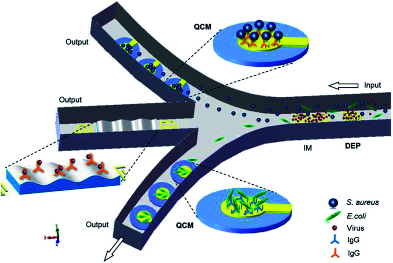
Real-time detection of pathogenic microorganisms in water, food, and airborne sources can prevent food poisoning and respiratory infections. The DEP technology precisely discriminates bio-targets, such as DNAs, proteins, viruses and bacteria, from a sample containing non-target species. The major issue is that individual biomolecules have very similar and very small induced dipole moments, and a high field gradient is required to generate a substantial DEP force.181 Thus, further research on the design of DEP systems is required for the effective fluidic manipulation of multi-particles. Microfabrication techniques can help in achieving better designs, cost-effectiveness and efficiency. In addition, some quantitative technologies and methodologies, such as impedance spectroscopy (IM), quartz crystal microbalance (QCM) and surface acoustic wave (SAW), can be integrated into microfluidic channels to form DEP-on-a-chip, which will improve the efficiency and accuracy of separation and detection, as shown in Fig. 9.
Fig. 9. A DEP-on-a-chip platform advanced by IM, QCM and SAW in the network of microfluidic channels.
IM allows continuous monitoring of the electrical properties, such as impedance amplitude, phase, conductance, and capacitance, of bio-samples in a microfluidic network for the characterization and differentiation of various types of particles in a frequency domain. QCM biosensors exploit the changes in mechanical properties of the interface between particles and an oscillating quartz crystal to detect micro-scaled particles (e.g., cells, bacteria and minerals). Moreover, QCM-based immunosensors182 are capable of detecting specificity and non-specificity by immobilization of selective antibodies.183 Furthermore, SAW-based immunosensors184 have a higher mass sensitivity to accurately detect nano-scaled particles.185
The combination of high-throughput capabilities of SAW with the exquisite discriminatory capabilities of DEP and mass sensitivity of QCM in a DEP-on-a-chip system can be a key to the development of rapid, accurate, portable, simple and cost-effective microfluidic devices with a promising impact in multi-particle manipulation, microfluidic, immune analysis, micro-total analysis systems (μTAS) and bond-rupture analysis systems.
Conflicts of interest
There are no conflicts to declare.
Supplementary Material
Acknowledgments
This study was supported by the National Key R&D Program of China (2016YFB1200401-102E) to YJY.
Biographies
Biography
Qiaoying Chen.

Qiaoying Chen has been pursuing a PhD degree in Materials Science at Southwest Jiaotong University, Chengdu, China since 2011. She received her Bachelor’s degree from Chongqing University in 2010. Her research interests include dielectrophoresis systems, biosensors, and microbiological detection. Publication list: Y. J. Yuan, Q. Chen, J. Li, QCM-based immunosensor for determining immunoglobulin G, RSC Adv., 2016, 6(46), 40336–40342.
Biography
Yong J. Yuan.

Yong J. Yuan received his PhD degree in biosensors from the University of Western Sydney, Australia, in 1997. He is a Professor of BioMEMS in the School of Materials Science and Engineering at Southwest Jiaotong University (SWJTU), China. Prior to joining SWJTU in 2008, he was a Research Chemist at CSIRO (1997–1999) working on oxygen scavenging materials, a Guest Researcher of the Agency of Industrial Science and Technology in Japan (1999–2000) conducting research on the metabolic oscillation of yeast, and a Research Program Leader at the Industrial Research Limited of New Zealand (2000–2008) to develop biochips by the integration of novel materials, structures, devices, and processes. His current research interests include biomedical sensors, MEMS, nano/micro devices and fabrication.
References
- Towbin H. Staehelin T. Gordon J. Proc. Natl. Acad. Sci. U. S. A. 1979;76:4350–4354. doi: 10.1073/pnas.76.9.4350. [DOI] [PMC free article] [PubMed] [Google Scholar]
- Pohl H. A. Crane J. S. Biophys. J. 1971;11:711–727. doi: 10.1016/S0006-3495(71)86249-5. [DOI] [PMC free article] [PubMed] [Google Scholar]
- Gagnon Z. Gordon J. Sengupta S. Chang H. C. Electrophoresis. 2008;29:2272–2279. doi: 10.1002/elps.200700604. [DOI] [PubMed] [Google Scholar]
- Neuman K. C. Nagy A. Nat. Methods. 2008;5:491–505. doi: 10.1038/nmeth.1218. [DOI] [PMC free article] [PubMed] [Google Scholar]
- Kim Y. Hong S. Jung S. Strano M. S. Choi J. Baik S. J. Phys. Chem. B. 2006;110:1541–1545. doi: 10.1021/jp055110c. [DOI] [PubMed] [Google Scholar]
- Krupke R. Hennrich F. von Lohneysen H. Kappes M. M. Science. 2003;301:344–347. doi: 10.1126/science.1086534. [DOI] [PubMed] [Google Scholar]
- Gimsa J. Muller T. Schnelle T. Fuhr G. Biophys. J. 1996;71:495–506. doi: 10.1016/S0006-3495(96)79251-2. [DOI] [PMC free article] [PubMed] [Google Scholar]
- Suehiro J. Hatano T. Shutou M. Hara M. Sens. Actuators, B. 2005;109:209–215. doi: 10.1016/j.snb.2004.12.048. [DOI] [Google Scholar]
- Di Carlo D. Irimia D. Tompkins R. G. Toner M. Proc. Natl. Acad. Sci. U. S. A. 2007;104:18892–18897. doi: 10.1073/pnas.0704958104. [DOI] [PMC free article] [PubMed] [Google Scholar]
- Lauga E. Powers T. R. Rep. Prog. Phys. 2009;72:096601. doi: 10.1088/0034-4885/72/9/096601. [DOI] [Google Scholar]
- Ding X. Lin S.-C. S. Kiraly B. Yue H. Li S. Chiang I. K. Shi J. Benkovic S. J. Huang T. J. Proc. Natl. Acad. Sci. U. S. A. 2012;109:11105–11109. doi: 10.1073/pnas.1209288109. [DOI] [PMC free article] [PubMed] [Google Scholar]
- Green N. G., in Electrokinetics And Electrohydrodynamics In Microsystems, ed. A. Ramos, 2011, vol. 530, pp. 61–84 [Google Scholar]
- Green N. G. Morgan H. J. Phys. D: Appl. Phys. 1997;30:2626–2633. doi: 10.1088/0022-3727/30/18/018. [DOI] [Google Scholar]
- Pethig R. Biomicrofluidics. 2010;4:022811. doi: 10.1063/1.3456626. [DOI] [PMC free article] [PubMed] [Google Scholar]
- Jones T. B. Bliss G. W. J. Appl. Phys. 1977;48:1412–1417. doi: 10.1063/1.323806. [DOI] [Google Scholar]
- Arnold W. M. IEEE Trans. Ind. Appl. 2001;37:1468–1475. doi: 10.1109/28.952523. [DOI] [Google Scholar]
- Yuan Y. J. Andrews M. K. Marlow B. K. Appl. Phys. Lett. 2004;85:130–132. doi: 10.1063/1.1766072. [DOI] [Google Scholar]
- Khoshmanesh K. Zhang C. Nahavandi S. Tovar-Lopez F. J. Baratchi S. Mitchell A. Kalantar-Zadeh K. J. Appl. Phys. 2010;108:034904. doi: 10.1063/1.3457226. [DOI] [Google Scholar]
- Hughes M. P. Morgan H. Anal. Chem. 1999;71:3441–3445. doi: 10.1021/ac990172i. [DOI] [Google Scholar]
- Duchamp M. Lee K. Dwir B. Seo J. W. Kapon E. Forro L. Magrez A. ACS Nano. 2010;4:279–284. doi: 10.1021/nn901559q. [DOI] [PubMed] [Google Scholar]
- Kim D.-J. Hyung J.-H. Seo D.-W. Suh D.-I. Lee S.-K. J. Electron. Mater. 2010;39:563–567. doi: 10.1007/s11664-009-0984-z. [DOI] [Google Scholar]
- Lao C. S. Liu J. Gao P. X. Zhang L. Y. Davidovic D. Tummala R. Wang Z. L. Nano Lett. 2006;6:263–266. doi: 10.1021/nl052239p. [DOI] [PubMed] [Google Scholar]
- Regtmeier J. Duong T. T. Eichhorn R. Anselmetti D. Ros A. Anal. Chem. 2007;79:3925–3932. doi: 10.1021/ac062431r. [DOI] [PubMed] [Google Scholar]
- Nakano M. Ding Z. Suehiro J. Jpn. J. Appl. Phys. 2016;55:017001. doi: 10.7567/JJAP.55.017001. [DOI] [Google Scholar]
- Hughes M. P., Flynn M. F. and Morgan H., in Electrostatics, ed. D. M. Taylor, 1999, vol. 163, pp. 81–84 [Google Scholar]
- Mansor M. A. Ahmad M. R. Int. J. Mol. Sci. 2015;16:12686–12712. doi: 10.3390/ijms160612686. [DOI] [PMC free article] [PubMed] [Google Scholar]
- Kasetsirikul S. Buranapong J. Srituravanich W. Kaewthamasorn M. Pimpin A. Malar. J. 2016;15:358. doi: 10.1186/s12936-016-1400-9. [DOI] [PMC free article] [PubMed] [Google Scholar]
- Adekanmbi E. O. Srivastava S. K. Lab Chip. 2016;16:2148–2167. doi: 10.1039/C6LC00355A. [DOI] [PubMed] [Google Scholar]
- Páez-Avilés C. Juanola-Feliu E. Punter-Villagrasa J. del Moral Zamora B. Homs-Corbera A. Colomer-Farrarons J. Lluis Miribel-Catala P. Samitier J. Sensors. 2016;16:1514. doi: 10.3390/s16091514. [DOI] [PMC free article] [PubMed] [Google Scholar]
- Viefhues M. Eichhorn R. Electrophoresis. 2017;38:1483–1506. doi: 10.1002/elps.201600482. [DOI] [PubMed] [Google Scholar]
- Modchang C. Triampo W. Kanthang P. Triampo D. Lenbury Y. Anal. Chem. 2008;53:851–862. [Google Scholar]
- Cetin B. Li D. Electrophoresis. 2011;32:2410–2427. doi: 10.1002/elps.201100167. [DOI] [PubMed] [Google Scholar]
- Dash S. Mohanty S. Electrophoresis. 2014;35:2656–2672. doi: 10.1002/elps.201400084. [DOI] [PubMed] [Google Scholar]
- Chen D. F. Du H. Li W. H. Sens. Actuators, A. 2007;133:329–334. doi: 10.1016/j.sna.2006.06.029. [DOI] [Google Scholar]
- Lewpiriyawong N. Yang C. Lam Y. C. Microfluid. Nanofluid. 2012;12:723–733. doi: 10.1007/s10404-011-0919-x. [DOI] [Google Scholar]
- Barik A. Chen X. Oh S.-H. Nano Lett. 2016;16:6317–6324. doi: 10.1021/acs.nanolett.6b02690. [DOI] [PubMed] [Google Scholar]
- Kadaksham A. T. J. Singh P. Aubry N. Electrophoresis. 2004;25:3625–3632. doi: 10.1002/elps.200406092. [DOI] [PubMed] [Google Scholar]
- Lin S.-C. Tung Y.-C. Lin C.-T. Appl. Phys. Lett. 2016;109:053701. doi: 10.1063/1.4960359. [DOI] [Google Scholar]
- Kralj J. G. Lis M. T. W. Schmidt M. A. Jensen K. F. Anal. Chem. 2006;78:5019–5025. doi: 10.1021/ac0601314. [DOI] [PubMed] [Google Scholar]
- Kale A. Patel S. Hu G. Xuan X. Electrophoresis. 2013;34:674–683. doi: 10.1002/elps.201200501. [DOI] [PubMed] [Google Scholar]
- Sadeghian H. Hojjat Y. Soleimani M. J. Electrost. 2017;86:41–49. doi: 10.1016/j.elstat.2017.01.012. [DOI] [Google Scholar]
- Jones T. B. Washizu M. J. Electrost. 1996;37:121–134. doi: 10.1016/0304-3886(96)00006-X. [DOI] [Google Scholar]
- Giner V. Sancho M. Lee R. S. Martinez G. Pethig R. J. Phys. D: Appl. Phys. 1999;32:1182–1186. doi: 10.1088/0022-3727/32/10/316. [DOI] [Google Scholar]
- Sancho M. Martinez G. Llamas M. J. Electrost. 1988;21:135–144. doi: 10.1016/0304-3886(88)90025-3. [DOI] [Google Scholar]
- Xie C. Chen B. Ng C.-O. Zhou X. Wu J. European Journal of Mechanics, B: Fluids. 2015;49:208–216. doi: 10.1016/j.euromechflu.2014.08.007. [DOI] [Google Scholar]
- Couniot N. Francis L. A. Flandre D. Lab Chip. 2015;15:3183–3191. doi: 10.1039/C5LC00090D. [DOI] [PubMed] [Google Scholar]
- Ai Y. Zeng Z. Qian S. J. Colloid Interface Sci. 2014;417:72–79. doi: 10.1016/j.jcis.2013.11.034. [DOI] [PubMed] [Google Scholar]
- Kang S. Comput. Fluids. 2014;105:231–243. doi: 10.1016/j.compfluid.2014.09.029. [DOI] [Google Scholar]
- Liu L. Xie C. Chen B. Chiu-On N. Wu J. Microsyst. Technol. 2016;22:2223–2232. doi: 10.1007/s00542-015-2624-2. [DOI] [Google Scholar]
- Arnold W. M. Microsyst. Technol. 2008;15:144–151. [Google Scholar]
- Griffin J. L. Ferris C. D. Nature. 1970;226:152–154. doi: 10.1038/226152a0. [DOI] [PubMed] [Google Scholar]
- Moncada-Hernandez H. Nagler E. Minerick A. R. Electrophoresis. 2014;35:1803–1813. doi: 10.1002/elps.201300636. [DOI] [PubMed] [Google Scholar]
- Wang X. B. Hughes M. P. Huang Y. Becker F. F. Gascoyne P. R. C. Biochim. Biophys. Acta, Gen. Subj. 1995;1243:185–194. doi: 10.1016/0304-4165(94)00146-O. [DOI] [PubMed] [Google Scholar]
- White C. M. Holland L. A. Famouri P. Electrophoresis. 2010;31:2664–2671. doi: 10.1002/elps.201000086. [DOI] [PubMed] [Google Scholar]
- Zhang C. Khoshmanesh K. Tovar-Lopez F. J. Mitchell A. Wlodarski W. Klantar-zadeh K. Microfluid. Nanofluid. 2009;7:633–645. doi: 10.1007/s10404-009-0419-4. [DOI] [Google Scholar]
- Cui L. Morgan H. J. Micromech. Microeng. 2000;10:72–79. doi: 10.1088/0960-1317/10/1/310. [DOI] [Google Scholar]
- Hennrich F. Krupke R. Kappes M. M. Lohneysen H. V. J. Nanosci. Nanotechnol. 2005;5:1166–1171. doi: 10.1166/jnn.2005.154. [DOI] [PubMed] [Google Scholar]
- Elitas M. Dhar N. Schneider K. Valero A. Braschler T. McKinney J. D. Renaud P. Biomedical Physics & Engineering Express. 2017;3:015005. [Google Scholar]
- Lapizco-Encinas B. H. Simmons B. A. Cummings E. B. Fintschenko Y. Anal. Chem. 2004;76:1571–1579. doi: 10.1021/ac034804j. [DOI] [PubMed] [Google Scholar]
- Cao Q. Han S.-j. Tulevski G. S. Nat. Commun. 2014;5:5071. doi: 10.1038/ncomms6071. [DOI] [PubMed] [Google Scholar]
- Yan S. Zhang J. Li M. Alici G. Du H. Sluyter R. Li W. Sci. Rep. 2014;4:5060. doi: 10.1038/srep05060. [DOI] [PMC free article] [PubMed] [Google Scholar]
- Das D. Biswas K. Das S. Med. Eng. Phys. 2014;36:726–731. doi: 10.1016/j.medengphy.2013.12.010. [DOI] [PubMed] [Google Scholar]
- Buyong M. R. Larki F. Faiz M. S. Hamzah A. A. Yunas J. Majlis B. Y. Sensors. 2015;15:10973–10990. doi: 10.3390/s150510973. [DOI] [PMC free article] [PubMed] [Google Scholar]
- Hamada R. Takayama H. Shonishi Y. Mao L. Nakano M. Suehiro J. Sens. Actuators, B. 2013;181:439–445. doi: 10.1016/j.snb.2013.02.030. [DOI] [Google Scholar]
- Martinez-Lopez J. I. Moncada-Hernandez H. Baylon-Cardiel J. L. Martinez-Chapa S. O. Rito-Palomares M. Lapizco-Encinas B. H. Anal. Bioanal. Chem. 2009;394:293–302. doi: 10.1007/s00216-009-2626-y. [DOI] [PubMed] [Google Scholar]
- Nahavandi M. Ind. Eng. Chem. Res. 2016;55:5484–5499. doi: 10.1021/acs.iecr.6b00660. [DOI] [Google Scholar]
- Fathy J., Pourmand A. and Badri Ghavifekr H., Iranian Conference on Electrical Engineering, 2017 [Google Scholar]
- Chiu T.-K. Chou W.-P. Huang S.-B. Wang H.-M. Lin Y.-C. Hsieh C.-H. Wu M.-H. Sci. Rep. 2016;6:32851. doi: 10.1038/srep32851. [DOI] [PMC free article] [PubMed] [Google Scholar]
- Samiei E. Nejad H. R. Hoorfar M. Appl. Phys. Lett. 2015;106:204101. doi: 10.1063/1.4921630. [DOI] [Google Scholar]
- Ravula S. K. Branch D. W. James C. D. Townsend R. J. Hill M. Kaduchak G. Ward M. Brener I. Sens. Actuators, B. 2008;130:645–652. doi: 10.1016/j.snb.2007.10.024. [DOI] [Google Scholar]
- Jen C.-P. Weng C.-H. Huang C.-T. Electrophoresis. 2011;32:2428–2435. doi: 10.1002/elps.201100085. [DOI] [PubMed] [Google Scholar]
- Chuang C.-H. Huang Y.-W. Electrophoresis. 2013;34:3111–3118. doi: 10.1002/elps.201300258. [DOI] [PubMed] [Google Scholar]
- Chuang C.-H. Huang Y.-W. Wu Y.-T. Biomed. Microdevices. 2012;14:271–278. doi: 10.1007/s10544-011-9603-x. [DOI] [PubMed] [Google Scholar]
- Huang H. Y. Huang Y. H. Kao W. L. Yao D. J. Biomicrofluidics. 2015;9:022404. doi: 10.1063/1.4915612. [DOI] [PMC free article] [PubMed] [Google Scholar]
- Golan S. Elata D. Dinnar U. Sens. Actuators, A. 2008;142:138–146. doi: 10.1016/j.sna.2007.04.063. [DOI] [Google Scholar]
- Nasabi M. Khoshmanesh K. Tovar-Lopez F. J. Kalantar-zadeh K. Mitchell A. Electrophoresis. 2013;34:3150–3154. doi: 10.1002/elps.201300233. [DOI] [PubMed] [Google Scholar]
- Rajaraman S. Noh H. Hesketh P. J. Gottfried D. S. Sens. Actuators, B. 2006;114:392–401. doi: 10.1016/j.snb.2005.06.022. [DOI] [Google Scholar]
- Kayani A. A. Chrimes A. F. Khoshmanesh K. Sivan V. Zeller E. Kalantar-zadeh K. Mitchell A. Microfluid. Nanofluid. 2011;11:93–104. doi: 10.1007/s10404-011-0777-6. [DOI] [Google Scholar]
- Zhao Y. Hu S. Wang Q. Microfluid. Nanofluid. 2014;17:287–294. doi: 10.1007/s10404-013-1311-9. [DOI] [Google Scholar]
- Pohl H. A. Hawk I. Science. 1966;152:647–649. doi: 10.1126/science.152.3722.647-a. [DOI] [PubMed] [Google Scholar]
- Mischel M. Rougé F. Lamprecht I. Aubert C. Prota G. Arch. Dermatol. Res. 1983;275:141. doi: 10.1007/BF00510042. [DOI] [PubMed] [Google Scholar]
- Vienken J. Zimmermann U. Alonso A. Chapman D. Naturwissenschaften. 1984;71:158–160. doi: 10.1007/BF01137784. [DOI] [PubMed] [Google Scholar]
- Becker F. F. Wang X. B. Huang Y. Pethig R. Vykoukal J. Gascoyne P. R. C. Proc. Natl. Acad. Sci. U. S. A. 1995;92:860–864. doi: 10.1073/pnas.92.3.860. [DOI] [PMC free article] [PubMed] [Google Scholar]
- Kaler K. Jones T. B. Biophys. J. 1990;57:173–182. doi: 10.1016/S0006-3495(90)82520-0. [DOI] [PMC free article] [PubMed] [Google Scholar]
- Chrimes A. F. Khoshmanesh K. Stoddart P. R. Kayani A. A. Mitchell A. Daima H. Bansal V. Kalantar-zadeh K. Anal. Chem. 2012;84:4029–4035. doi: 10.1021/ac203381n. [DOI] [PubMed] [Google Scholar]
- Bezryadin A. Dekker C. Schmid G. Appl. Phys. Lett. 1997;71:1273–1275. doi: 10.1063/1.119871. [DOI] [Google Scholar]
- Jung S.-H. Chen C. Cha S.-H. Yeom B. Bahng J. H. Srivastava S. Zhu J. Yang M. Liu S. Kotov N. A. J. Am. Chem. Soc. 2011;133:10688–10691. doi: 10.1021/ja200422s. [DOI] [PMC free article] [PubMed] [Google Scholar]
- Kuehn S. Measor P. Lunt E. J. Phillips B. S. Deamer D. W. Hawkins A. R. Schmidt H. Lab Chip. 2009;9:2212–2216. doi: 10.1039/B900555B. [DOI] [PMC free article] [PubMed] [Google Scholar]
- Riahifar R. Marzbanrad E. Raissi B. Zamani C. Kazemzad M. Aghaei A. Mater. Lett. 2011;65:632–635. doi: 10.1016/j.matlet.2010.08.029. [DOI] [Google Scholar]
- Zhang L. Zhu Y. Langmuir. 2012;28:13201–13207. doi: 10.1021/la302725v. [DOI] [PubMed] [Google Scholar]
- Park S. Koklu M. Beskok A. Anal. Chem. 2009;81:2303–2310. doi: 10.1021/ac802471g. [DOI] [PubMed] [Google Scholar]
- Antfolk M. Kim S. H. Koizumi S. Fujii T. Laurell T. Sci. Rep. 2017;7:46507. doi: 10.1038/srep46507. [DOI] [PMC free article] [PubMed] [Google Scholar]
- Song Y. Yang J. Shi X. Jiang H. Wu Y. Peng R. Wang Q. Gong N. Pan X. Sun Y. Li D. Sci. China: Chem. 2012;55:524–530. doi: 10.1007/s11426-012-4533-x. [DOI] [Google Scholar]
- Demierre N. Braschler T. Muller R. Renaud P. Sens. Actuators, B. 2008;132:388–396. doi: 10.1016/j.snb.2007.09.078. [DOI] [Google Scholar]
- Gupta S. Alargova R. G. Kilpatrick P. K. Velev O. D. Langmuir. 2010;26:3441–3452. doi: 10.1021/la902989r. [DOI] [PubMed] [Google Scholar]
- Ismail A. Hughes M. P. Mulhall H. J. Oreffo R. O. C. Labeed F. H. J. Tissue Eng. Regener. Med. 2015;9:162–168. doi: 10.1002/term.1629. [DOI] [PubMed] [Google Scholar]
- Pui-ock S. Ruchirawat M. Gascoyne P. Anal. Chem. 2008;80:7727–7734. doi: 10.1021/ac801095p. [DOI] [PMC free article] [PubMed] [Google Scholar]
- Kang S. European Journal of Mechanics, B: Fluids. 2015;54:53–68. doi: 10.1016/j.euromechflu.2015.06.014. [DOI] [Google Scholar]
- Hawkins B. G. Huang C. Arasanipalai S. Kirby B. J. Anal. Chem. 2011;83:3507–3515. doi: 10.1021/ac2002017. [DOI] [PubMed] [Google Scholar]
- Safavieh M. Khetani S. Juillard F. Kaul V. Kanakasabapathy M. K. Kaye K. M. Shafiee H. Biosens. Bioelectron. 2016;80:230–236. doi: 10.1016/j.bios.2016.01.060. [DOI] [PMC free article] [PubMed] [Google Scholar]
- Pysher M. D. Hayes M. A. Anal. Chem. 2007;79:4552–4557. doi: 10.1021/ac070534j. [DOI] [PubMed] [Google Scholar]
- Yang L. Anal. Lett. 2012;45:187–201. doi: 10.1080/00032719.2011.633182. [DOI] [Google Scholar]
- Chung C. C. Cheng I. F. Chen H. M. Kan H. C. Yang W. H. Chang H. C. Anal. Chem. 2012;84:3347–3354. doi: 10.1021/ac300093w. [DOI] [PubMed] [Google Scholar]
- Llamas M. Giner V. Sancho M. J. Phys. D: Appl. Phys. 1998;31:3160–3167. doi: 10.1088/0022-3727/31/21/023. [DOI] [Google Scholar]
- Khoshmanesh K. Baratchi S. Tovar-Lopez F. J. Nahavandi S. Wlodkowic D. Mitchell A. Kalantar-zadeh K. Microfluid. Nanofluid. 2012;12:597–606. doi: 10.1007/s10404-011-0900-8. [DOI] [Google Scholar]
- Ramon-Azcon J. Yasukawa T. Mizutani F. Anal. Chem. 2011;83:1053–1060. doi: 10.1021/ac102854z. [DOI] [PubMed] [Google Scholar]
- Du F. Hawari A. Baune M. Thoeming J. J. Membr. Sci. 2009;336:71–78. doi: 10.1016/j.memsci.2009.03.010. [DOI] [Google Scholar]
- Dommersnes P. Rozynek Z. Mikkelsen A. Castberg R. Kjerstad K. Hersvik K. Fossum J. O. Nat. Commun. 2013;4:2066. doi: 10.1038/ncomms3066. [DOI] [PMC free article] [PubMed] [Google Scholar]
- Ballantyne G. R. Holtham P. N. Miner. Eng. 2014;55:75–79. doi: 10.1016/j.mineng.2013.09.009. [DOI] [Google Scholar]
- Tao Q. Jiang M. Li G. IEEE Trans. Nanotechnol. 2014;13:517–526. [Google Scholar]
- Wu J. Yin B. Wu F. Myung Y. Banerjee P. Appl. Phys. Lett. 2014;105:183506. doi: 10.1063/1.4900966. [DOI] [Google Scholar]
- Nerowski A. Poetschke M. Bobeth M. Opitz J. Cuniberti G. Langmuir. 2012;28:7498–7504. doi: 10.1021/la300302n. [DOI] [PubMed] [Google Scholar]
- Maijenburg A. W. Maas M. G. Rodijk E. J. B. Ahmed W. Kooij E. S. Carlen E. T. Blank D. H. A. ten Elshof J. E. J. Colloid Interface Sci. 2011;355:486–493. doi: 10.1016/j.jcis.2010.12.011. [DOI] [PubMed] [Google Scholar]
- Ahadian S. Naito U. Surya V. J. Darvishi S. Estili M. Liang X. Nakajima K. Shiku H. Kawazoe Y. Matsue T. Carbon. 2017;123:460–470. doi: 10.1016/j.carbon.2017.07.082. [DOI] [Google Scholar]
- Gupta M. K. Sinha N. Singh B. K. Kumar B. Mater. Lett. 2010;64:1825–1828. doi: 10.1016/j.matlet.2010.05.044. [DOI] [Google Scholar]
- Kumar S. Peng Z. Shin H. Wang Z. L. Hesketh P. J. Anal. Chem. 2010;82:2204–2212. doi: 10.1021/ac901287z. [DOI] [PubMed] [Google Scholar]
- Liu W. Zhu J. Wang Z. Tang X. Phys. E. 2010;42:1653–1658. doi: 10.1016/j.physe.2010.01.020. [DOI] [Google Scholar]
- Regtmeier J. Eichhorn R. Bogunovic L. Ros A. Anselmetti D. Anal. Chem. 2010;82:7141–7149. doi: 10.1021/ac1005475. [DOI] [PubMed] [Google Scholar]
- Masuda T. Maruyama H. Honda A. Arai F. PLoS One. 2014;9(6):e94083. doi: 10.1371/journal.pone.0094083. [DOI] [PMC free article] [PubMed] [Google Scholar]
- Sonnenberg A. Marciniak J. Y. McCanna J. Krishnan R. Rassenti L. Kipps T. J. Heller M. J. Electrophoresis. 2013;34:1076–1084. doi: 10.1002/elps.201200444. [DOI] [PMC free article] [PubMed] [Google Scholar]
- Burt J. P. H. Al-Ameen T. A. K. Pethig R. J. Phys. E: Sci. Instrum. 1989;22:952–957. doi: 10.1088/0022-3735/22/11/011. [DOI] [Google Scholar]
- Fuhr G. Muller T. Baukloh V. Lucas K. Hum. Reprod. 1998;13:136–141. doi: 10.1093/humrep/13.1.136. [DOI] [PubMed] [Google Scholar]
- Archer S. Morgan H. Rixon F. J. Biophys. J. 1999;76:2833–2842. doi: 10.1016/S0006-3495(99)77437-0. [DOI] [PMC free article] [PubMed] [Google Scholar]
- Kim S. Asmatulu R. Marcus H. L. Papadimitrakopoulos F. J. Colloid Interface Sci. 2011;354:448–454. doi: 10.1016/j.jcis.2010.11.023. [DOI] [PubMed] [Google Scholar]
- Ibrahim S. N. Murray L. Nock V. Evans J. J. Alkaisi M. M. Microelectron. Eng. 2012;97:369–374. doi: 10.1016/j.mee.2012.04.018. [DOI] [Google Scholar]
- Haapalainen M. and Mäkynen A., in Optical Trapping And Optical Micromanipulation Vii, ed. K. Dholakia and G. C. Spalding, 2010, p. 7762 [Google Scholar]
- Freedman K. J. Otto L. M. Ivanov A. P. Barik A. Oh S. H. Edel J. B. Nat. Commun. 2016;7:10217. doi: 10.1038/ncomms10217. [DOI] [PMC free article] [PubMed] [Google Scholar]
- Jones P. V. Salmon G. L. Ros A. Anal. Chem. 2017;89:1531–1539. doi: 10.1021/acs.analchem.6b03369. [DOI] [PubMed] [Google Scholar]
- Shafiee H. Caldwell J. L. Davalos R. V. JALA. 2010;15:224–232. [Google Scholar]
- Mohammadi M. Zare M. J. Madadi H. Sellares J. Casals-Terre J. Anal. Bioanal. Chem. 2016;408:5285–5294. doi: 10.1007/s00216-016-9629-2. [DOI] [PubMed] [Google Scholar]
- McMullan J. M. Wagner N. J. Langmuir. 2012;28:4123–4130. doi: 10.1021/la204780p. [DOI] [PubMed] [Google Scholar]
- Garcia-Sanchez P. Ren Y. Arcenegui J. J. Morgan H. Ramos A. Langmuir. 2012;28:13861–13870. doi: 10.1021/la302402v. [DOI] [PubMed] [Google Scholar]
- Li S. Li M. Bougot-Robin K. Cao W. Chau I. Y. Y. Li W. Wen W. Biomicrofluidics. 2013;7(2):024106. doi: 10.1063/1.4795856. [DOI] [PMC free article] [PubMed] [Google Scholar]
- Ben-Bassat D. Boymelgreen A. Yossifon G. J. Colloid Interface Sci. 2015;442:154–161. doi: 10.1016/j.jcis.2014.11.037. [DOI] [PubMed] [Google Scholar]
- Perez-Gonzalez V. H. Vinh H. Vazquez-Pinon M. Martinez-Chapa S. O. Kulinsky L. J. Micromech. Microeng. 2015;25(11):115007. doi: 10.1088/0960-1317/25/11/115007. [DOI] [Google Scholar]
- Kale A. Lu X. Patel S. Xuan X. J. Micromech. Microeng. 2014;24:075007. doi: 10.1088/0960-1317/24/7/075007. [DOI] [Google Scholar]
- Nerguizian V. Alazzam A. Gauthier J. Roman D. Stiharu I. Burnier M. Proc. Inst. Mech. Eng., Part B. 2016;230:1309–1316. doi: 10.1177/0954405415615801. [DOI] [Google Scholar]
- Allen D. J. Accolla R. P. Williams S. J. Electrophoresis. 2017;38:1441–1449. doi: 10.1002/elps.201600517. [DOI] [PubMed] [Google Scholar]
- Luo Y. Yobas L. Appl. Phys. Lett. 2014;105(9):094105. doi: 10.1063/1.4894731. [DOI] [PMC free article] [PubMed] [Google Scholar]
- Jen C.-P. Maslov N. A. Shih H.-Y. Lee Y.-C. Hsiao F.-B. Microsyst. Technol. 2012;18:1879–1886. doi: 10.1007/s00542-012-1498-9. [DOI] [Google Scholar]
- Guler M. T. Bilican I. Agan S. Elbuken C. J. Micromech. Microeng. 2015;25(9):095019. doi: 10.1088/0960-1317/25/9/095019. [DOI] [Google Scholar]
- Su H.-W. Prieto J. L. Voldman J. Lab Chip. 2013;13:4109–4117. doi: 10.1039/C3LC50392E. [DOI] [PubMed] [Google Scholar]
- Tirapu-Azpiroz J. Temiz Y. Delamarche E. Appl. Phys. Lett. 2015;107:204102. doi: 10.1063/1.4935858. [DOI] [Google Scholar]
- Voldman J., Braff R. A., Toner M., Gray M. L. and Schmidt M. A., Micro Total Analysis Systems, 2000, pp. 431–434 [Google Scholar]
- Saucedo-Espinosa M. A. LaLonde A. Gencoglu A. Romero-Creel M. F. Dolas J. R. Lapizco-Encinas B. H. Electrophoresis. 2016;37:282–290. doi: 10.1002/elps.201500195. [DOI] [PubMed] [Google Scholar]
- Saucedo-Espinosa M. A. Lapizco-Encinas B. H. Electrophoresis. 2015;36:1086–1097. doi: 10.1002/elps.201400408. [DOI] [PubMed] [Google Scholar]
- Kale A. Patel S. Qian S. Hu G. Xuan X. Electrophoresis. 2014;35:721–727. doi: 10.1002/elps.201300343. [DOI] [PubMed] [Google Scholar]
- Gallo-Villanueva R. C. Sano M. B. Lapizco-Encinas B. H. Davalos R. V. Electrophoresis. 2014;35:352–361. doi: 10.1002/elps.201300171. [DOI] [PMC free article] [PubMed] [Google Scholar]
- Tanaka S. Tsutsui M. Theodore H. He Y. Arima A. Tsuji T. Doi K. Kawano S. Taniguchi M. Kawai T. Sci. Rep. 2016;6:31670. doi: 10.1038/srep31670. [DOI] [PMC free article] [PubMed] [Google Scholar]
- Kirmani S. A. M. Gudagunti F. D. Velmanickam L. Nawarathna D. Lima Jr I. T. J. Biomed. Opt. 2017;22:037006. doi: 10.1117/1.JBO.22.3.037006. [DOI] [PubMed] [Google Scholar]
- Zhou P. Yu H. Yang W. Wen Y. Wang Z. Li W. J. Liu L. ACS Appl. Mater. Interfaces. 2017;9:16715–16724. doi: 10.1021/acsami.7b03565. [DOI] [PubMed] [Google Scholar]
- Tao Y. Wickramasinghe H. K. Appl. Phys. Lett. 2017;110:073701. doi: 10.1063/1.4974939. [DOI] [Google Scholar]
- Stanke S. Bier F. F. Hoezel R. Electrophoresis. 2011;32:2448–2455. doi: 10.1002/elps.201100096. [DOI] [PubMed] [Google Scholar]
- Yan Y. Luo J. Guo D. Wen S. PLoS One. 2015;10:0117456. doi: 10.1371/journal.pone.0117456. [DOI] [PMC free article] [PubMed] [Google Scholar]
- Zhang L. Zhu Y. Appl. Phys. Lett. 2010;96(14):141902. doi: 10.1063/1.3378687. [DOI] [Google Scholar]
- Javanmard M. Emaminejad S. Dutton R. W. Davis R. W. Anal. Chem. 2012;84:1432–1438. doi: 10.1021/ac202508u. [DOI] [PMC free article] [PubMed] [Google Scholar]
- Park I. S. Eom K. Son J. Chang W.-J. Park K. Kwon T. Yoon D. S. Bashir R. Lee S. W. ACS Nano. 2012;6:8665–8673. doi: 10.1021/nn302202t. [DOI] [PubMed] [Google Scholar]
- Yamaguchi A. Fukuoka T. Kuroda K. Hara R. Utsumi Y. Colloids Surf., A. 2016;507:118–123. doi: 10.1016/j.colsurfa.2016.07.094. [DOI] [Google Scholar]
- Kim M. H. Lee J. Nam K. Park I. S. Son M. Ko H. Lee S. Yoon D. S. Chang W.-J. Lee S. Y. Yoon Y. R. Lee S. W. Sensors. 2017;17(10):2272. doi: 10.3390/s17102272. [DOI] [PMC free article] [PubMed] [Google Scholar]
- Hanson C. Vargis E. Sensors. 2017;17:327. doi: 10.3390/s17020327. [DOI] [PMC free article] [PubMed] [Google Scholar]
- Yamaguchi A. Fukuoka T. Takahashi R. Hara R. Utsumi Y. Sens. Actuators, B. 2016;230:94–100. doi: 10.1016/j.snb.2016.02.023. [DOI] [Google Scholar]
- Kanagasabapathi T. T., Dalton C., and Kaler K. V. I. S., Asme 3rd International Conference on Microchannels and Minichannels, Pt B, 2005 [Google Scholar]
- Zhang W. Radadia A. D. Anal. Chem. 2016;88:2605–2613. doi: 10.1021/acs.analchem.5b03227. [DOI] [PubMed] [Google Scholar]
- Romero-Creel M. F. Goodrich E. Polniak D. V. Lapizco-Encinas B. H. Micromachines. 2017;8:239. doi: 10.3390/mi8080239. [DOI] [PMC free article] [PubMed] [Google Scholar]
- Yahya N. N., Abd Aziz N., Buyong M. R. and Majlis B. Y., IEEE. RSM, 2017 [Google Scholar]
- Sun J. Gao Y. Isaacs R. J. Boelte K. C. Lin P. C. Boczko E. M. Li D. Anal. Chem. 2012;84:2017–2024. doi: 10.1021/ac203212g. [DOI] [PMC free article] [PubMed] [Google Scholar]
- Viefhues M. Eichhorn R. Fredrich E. Regtmeier J. Anselmetti D. Lab Chip. 2012;12:485–494. doi: 10.1039/C1LC20610A. [DOI] [PubMed] [Google Scholar]
- Tao Y. Ren Y. Yan H. Jiang H. Chin. J. Mech. Eng. 2016;29:325–331. doi: 10.3901/CJME.2015.1028.128. [DOI] [Google Scholar]
- Lu X. Hsu J.-P. Xuan X. Langmuir. 2015;31:620–627. doi: 10.1021/la5045464. [DOI] [PubMed] [Google Scholar]
- Wang Y. Du F. Pesch G. R. Koeser J. Baune M. Thoeming J. Chem. Eng. Sci. 2016;153:34–44. doi: 10.1016/j.ces.2016.07.020. [DOI] [Google Scholar]
- Zhao K. Li D. J. Micromech. Microeng. 2017;27:274–284. [Google Scholar]
- Zhu J. Canter R. C. Keten G. Vedantam P. Tzeng T.-R. J. Xuan X. Microfluid. Nanofluid. 2011;11:743–752. doi: 10.1007/s10404-011-0839-9. [DOI] [Google Scholar]
- Zhao K. Li D. Sens. Actuators, B. 2017;250:274–284. doi: 10.1016/j.snb.2017.04.184. [DOI] [Google Scholar]
- Zhu H. Lin X. Su Y. Dong H. Wu J. Biosens. Bioelectron. 2015;63:371–378. doi: 10.1016/j.bios.2014.07.072. [DOI] [PubMed] [Google Scholar]
- Afshar S. Salimi E. Braasch K. Butler M. Thomson D. J. Bridges G. E. IRE Trans. Microwave Theory Tech. 2016;64:991–998. [Google Scholar]
- Tang S.-Y. Zhang W. Soffe R. Nahavandi S. Shukla R. Khoshmanesh K. PLoS One. 2014;9:e104109. doi: 10.1371/journal.pone.0104109. [DOI] [PMC free article] [PubMed] [Google Scholar]
- LaLonde A. Romero-Creel M. F. Saucedo-Espinosa M. A. Lapizco-Encinas B. H. Biomicrofluidics. 2015;9(6):064113. doi: 10.1063/1.4936371. [DOI] [PMC free article] [PubMed] [Google Scholar]
- Lewpiriyawong N. Kandaswamy K. Yang C. Ivanov V. Stocker R. Anal. Chem. 2011;83:9579–9585. doi: 10.1021/ac202137y. [DOI] [PubMed] [Google Scholar]
- Jia Y. Ren Y. Jiang H. Electrophoresis. 2015;36:1744–1753. doi: 10.1002/elps.201400565. [DOI] [PubMed] [Google Scholar]
- Chow K.-S. Du H. Sens. Actuators, A. 2011;170:24–31. doi: 10.1016/j.sna.2011.03.053. [DOI] [Google Scholar]
- Tian K. Decker K. Aksimentiev A. Gu L.-Q. ACS Nano. 2017;11:1204–1213. doi: 10.1021/acsnano.6b07570. [DOI] [PMC free article] [PubMed] [Google Scholar]
- Yuan Y. J. Jia R. Nanomedicine. 2012;7:381. doi: 10.2147/IJN.S26808. [DOI] [PMC free article] [PubMed] [Google Scholar]
- Yuan Y. J. Pyatenko A. T. Suzuki M. Nanoscale Res. Lett. 2007;2:119–122. doi: 10.1007/s11671-007-9041-0. [DOI] [Google Scholar]
- Xu Z. Yuan Y. J. Biosens. Bioelectron. 2018;99:500–512. doi: 10.1016/j.bios.2017.07.060. [DOI] [PubMed] [Google Scholar]
- Seidel M. Niessner R. Anal. Bioanal. Chem. 2014;406:5589–5612. doi: 10.1007/s00216-014-7968-4. [DOI] [PubMed] [Google Scholar]


