Abstract
Although hydrophobic surface coating of concrete is currently used to enhance waterproofing performance of underground structures, the chemical and mechanical incompatibility between an inorganic cement and organic coating makes it a challenge to ensure long-term waterproofing properties of underground facilities, especially for tunnel lining systems. This study explores the feasibility of using a silane coupling agent to improve compatibility between the cement and tail sealant interface, which aims to reduce the water leakage risk of lining systems. The enhanced waterproofing performance of the cement–tail sealant interface modified with the silane agent was confirmed by its hydrophobicity (i.e. reduced wetting ability) and reduced permeability, which was evaluated by static water-contact angle and impermeability pressure measurements. The processes underlying the enhanced waterproofing performance of the cement–tail sealant interface were revealed by chemical bonding, microstructure and porosity characterization. Fourier transform infrared spectroscopy (FTIR) results of the cement–tail sealant interface confirm the reactions between the silane agent and cement hydration products, while both microstructure and porosity results reveal that the cement–tail sealant interface is denser and less porous, relative to the control cement grout.
Although hydrophobic surface coating of concrete is currently used to enhance waterproofing performance of underground structures, the chemical and mechanical incompatibility between them is a challenge to ensure long-term waterproofing properties.
1. Introduction
The waterproofing of underground or underwater concrete structures is of great significance to ensure desired performance and durability, which often relies on hydrophobic surface coatings that consist of organic ingredients, such as rubber, asphalt binder or other organic materials.1–3 For example, asphalt membranes and polyurethane waterproofing paint have been used as coating materials for underground garages and tunnels for decades.4,5 However, the origin of the hydrophobicity of most surface coatings lies in their own hydrophobic characteristics or simply physical adsorption with the concrete surface. Poor chemical and mechanical compatibility between organic and inorganic substances makes their interface most susceptible to water leaking, which remains a challenge facing the construction industry in terms of reliable long-term waterproofing performance of underground construction.6,7
Subway tunnel is supported with segmental linings, which are continuously placed side-by-side and then connected with each other by rubber pad and screw bolt, as tunnel boring machine advances (see Fig. 1).8 As shown in Fig. 1, tunnel lining is subjected to high stress, especially along longitudinal direction, and uneven deformation, and therefore it remains a challenge to ensure its waterproofing performance throughout the long service life of tunnels.9,10 Thanks to its high adhesion and excellent waterproofing, tail sealant is used to provide not only waterproofing and sealing of shield tail during tunneling, but also the long-term waterproofing performance of concrete segmental linings. The process of how tail sealant is applied to the surface of tunnel linings is schematically illustrated in Fig. 1a. Firstly, tail sealant is used to resist the grouting pressure and keep the slurry and soil out of the shield shell for a smooth tunnel excavation. Secondly, as the shield tunneling proceeds, tail sealant is left on the outer surface of concrete linings and the inner surface of cement grout.
Fig. 1. (a) Schematic illustration of how a tail shield is applied on the surface of linings, (b) a sketch map of transverse section of a tunnel lining system and (c) a picture of a typical cross-section of a tunnel lining system.
Tail sealant commonly used in tunneling in China is an organic composite and often composed of the following ingredients: base oil, adhesive, mineral fillers, and fibers.11,12 In order to enhance the compatibility with base oil and adhesive, the surfaces of the fibers and mineral filler particles, such as polypropylene fiber and calcium carbonate, need to be modified by surfactant to improve their surface activity. In general, mineral oil, vegetable oil and synthetic oil can be used as base oil that governs the fluidity and lubricity of tail sealant. Typical adhesives used in the tail sealant include: polyisobutylene, resin, rubber and asphalt and so on,12,13 which mainly affects adhesion between fibers, mineral fillers and base oil present in tail sealant. Similar to other organic–inorganic systems, the interface of cement–tail sealant is most susceptible to water leakage in the long run because of the mismatch in their mechanical properties and durability that leads to the formation of interfacial gap. Therefore, improving the chemical compatibility and adhesion between tail sealant and cement grout is a key issue to enhance the long-term waterproofing performance of tunnel lining.
It is well known that some coupling agents with both organic and inorganic groups are ready to combine with both inorganic and organic materials.14–17 Among commonly used coupling agents, silane coupling agents have been used to improve environmental durability of the epoxy/metal and epoxy/cement interfaces in recent years.18–20 Silane coupling agents usually contains an organofunctional group (Y) and alkoxy function group (OR), which can react with an inorganic (e.g., cement) through hydrolysis and condensation. Several studies of applying silane coupling agents to cement are reviewed herein. Alkyl-alkoxy-silane, such as 3-glycidyloxypropyl trimethoxy silane, vinyl trimethoxy silane and so on, was confirmed to reduce fluid entry into the concrete matrix through surface treatment in recent years.21–24 Xue et al. conducted a systematic investigation on waterproofing performance of octyltriethoxysilane-based hydrophobic agent and its water penetrability, which was treated on the surface of cured cement grout. The results demonstrated that the concrete treated by the hydrophobic agent led to increase in its water impermeability.25,26 Furthermore, Stewart et al.20 investigated the interaction between silane coupling agents and cured cement paste using X-ray photoelectron spectroscopy and static contact angle measurements. Their results confirmed the formation of a covalent bond between the cement paste and silane.
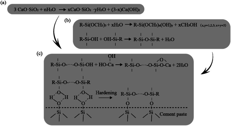
Based on the literature studies, the improvement in durability of epoxy–cement interface modified by silane was attributed to two possible mechanisms: (1) forming a covalent bond between cement and epoxy through chemical reactions of silane coupling agents with cement surface; and (2) hydrophobic barrier effect due to the hydrophobicity of silane coupling agents, which does not require chemical reaction of the silane with cement surface. For the former mechanism, the chemical reactions in the transition zone between cement paste and silane coating likely include:27–30 (i) hydration process of cement; (ii) hydrolysis–condensation of silane coupling agent; and (iii) reactions between siloxane oligomer and cement hydration products as schematically shown in Fig. 2a, b and c, respectively.
Fig. 2. A series of possible chemical reactions in the transition zone of cement and saline: (a) cement hydration, (b) hydrolysis–condensation of silane and (c) interaction between siloxane oligomer and hydration products.
However, in most of the literature studies silane agent was applied to the cured cement surface for enhancing its mechanical properties (e.g., durability and adhesion between cement/organic compounds) or performance since silane agent might intervene the hydration process. The feasibility and effectiveness of using silane coupling agents to enhance interfacial compatibility, adhesion and waterproofing between unhydrated cement paste and tail sealant has not been explored or reported. Therefore, this experimental study aimed to explore the feasibility of using silane coupling agents to enhance compatibility of cement–tail sealant interface for improving its waterproofing performance. In addition, the interaction at the cement–tail sealant interface enabled by silane coupling agent was also investigated. To this end, a series of experiments were performed. Firstly, the effectiveness of cement–tail sealant interface modified by silane coupling agent to enhance waterproofing performance was confirmed by hydrophilicity and permeability experiments. Secondly, the chemical bonding of cement–tail sealant interface was detected by Fourier transform infrared spectroscopy (FTIR) testing. Lastly, the microstructure and porosity of cement–tail sealant interface, which were evaluated with scanning electron microscope (SEM) technique and mercury intrusion porosimetry (MIP) testing, respectively, to shed light on the processes underlying the enhanced waterproofing performance of the cement–tail sealant interface.
2. Materials and experiments
2.1. Materials
Conventional tail sealant was used as the base material in this study, which is composed of hydraulic fluid, polyisobutylene, cotton fiber and active calcium carbonate. Among these ingredients, hydraulic fluid and polyisobutylene act as base oil and adhesive, respectively. Cotton fiber and active calcium carbonate were used as fibers and mineral fillers, respectively. The base tail sealant was prepared in accordance with the steps suggested by Liu et al.31
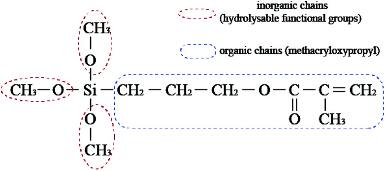
A γ-methacryloxypropyl trimethoxy silane (MPTMS), obtained from Aladdin chemical plant in Beijing, with its molecular structure shown in Fig. 3, was chosen as the coupling agent in this study for the following reasons: (i) MPTMS is a widely used silane coupling agent for cementitious materials and often used as modifying agent of organic composite, such as polyvinyl alcohol membrane and so on;32–34 (ii) MPTMS contains three hydrolysable functional groups (–OCH3) and thus can react with cement paste through hydrolysis–condensation processes in the presence of water; and (iii) MPTMS is widely available due to its relatively lower cost compared with other silane coupling agents.
Fig. 3. Molecular structure of MPTMS.
Type I ordinary Portland cement was used as raw material of cement grouting, which was provided by Shenzhen Haixing Onoda Cement Co., Ltd. Its contents of calcium silicate (C3S), dicalcium silicate (C2S), tricalcium aluminate (C3A), and tetra-calcium aluminoferrite (C4AF) were 59.36 wt%, 18.25 wt%, 9.82 wt%, and 10.18 wt%, respectively. According to the experience in tunneling, w/c ratio was set to 0.7 for the cement grout.35 The water used in following experiments is tap water of Beijing. All of the commercial chemicals were used as received without further purification in this study.
2.2. Cement–tail sealant interface modified by MPTMS
Conventional tail sealant was firstly modified by MPTMS, which in turn was used to prepare a composite sample with cement paste in the next section to examine possible interaction or chemical reaction at the cement–tail sealant interface. A predetermined amount of conventional tail sealant was placed into a beaker, into which 5 wt% MPTMS was added. The chosen concentration of MPTMS was based on the suggested mass ratio ranging from 2 wt% and 10 wt% of silane coupling agents for modified organic composite material, a product similar to tail sealant.36,37 Then the whole mixture was thoroughly mixed for 15 min by hand.
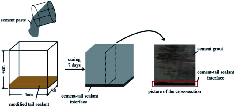
An interfacial layer between the cement paste and modified tail sealant was prepared for simulating the behavior of the cement grout–tail sealant interface in the tunnel lining system. As shown in Fig. 4, considered the real thickness of tail sealant left on the surface of cement paste in tunnel lining, a ∼5 mm thick film of modified tail sealant was evenly coated on the surface of the bottom of a cubic mold of 4 cm × 4 cm × 4 cm, above which a layer of pre-prepared cement paste with a w/c = 0.7 was casted and completely filled the mold. The composite sample was then cured at standard chamber at a constant temperature of 20 ± 2 °C and a relative humidity of 95% to simulate the real water-rich stratum condition of tunnel. The specimen was continuously cured until 7 days. Cement can complete more than 55% hydration process after 7 day curing as Wang et al. reported, compared with about 60% hydration degree after curing 28 days at same condition.38–40 Additionally, 7 day curing is enough for silane coupling agent to react with cement based on previous research studies.41,42
Fig. 4. Preparation steps of cement–tail sealant modified by MPTMS.
After curing, extra amount of the modified tail sealant at the bottom of cement paste was cleaned up, while the composite specimen was cut in half lengthwise to examine whether there was any interfacial transition zone formed. As expected, there was an obvious cement–tail sealant interface as show in Fig. 4. A series of laboratory experiments were performed that are detailed in the following sections to further characterize the cement–tail sealant interface and evaluate its influence on waterproofing performance of cement grout.
2.3. Waterproofing characteristics of cement–tail sealant interface
2.3.1. Anti-permeability measurements of interfacial layer
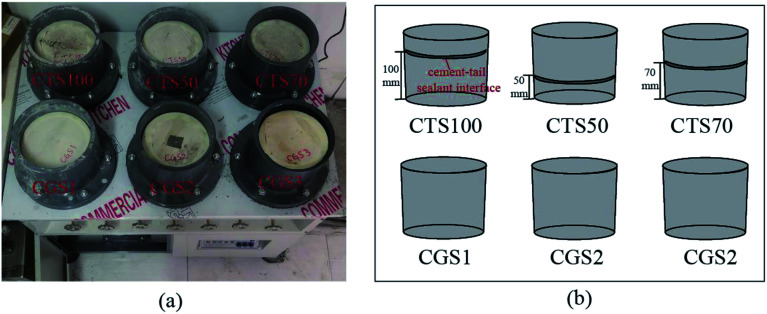
To analyze the effectiveness of cement–tail sealant interface modified by MPTMS on the waterproofing performance of cement grout, net cement grout specimens (CGS1, CGS2, CGS3) and composite specimens with the cement–tail sealant interface at different positions were prepared to evaluate their anti-permeability, which were conducted with pH-4.0 concrete permeability tester (Shanghai Le Ao Test Instrument Co., Ltd., China), as shown in Fig. 5. In tunnel lining, cement–tail sealant interface exists in the middle of cement grout and concrete lining at varying distance away from the edge of the cement grout, as previously shown in Fig. 1. Therefore, various positions of the interfacial layer within three cement grout specimens treated by modified sealant were considered for its influence on permeability, which include 50 mm (CTS50), 70 mm (CTS70) and 100 mm (CTS100) apart from the specimen bottom, respectively. Considering the sampling errors and instrumental errors, another two composite sample groups were prepared and their anti-permeability performance were measured to minimize these errors.
Fig. 5. (a) is the photo of concrete impermeability tester used in this work and (b) is the concept map of permeability samples, showing the position of cement–tail sealant interface.
Truncated-cone-shaped mold with 175 mm upper surface diameter, 185 mm bottom surface diameter and 150 mm in height, was used to prepare cement grout specimen and composite samples. The special shape was used for sample preparation in order to ensure that samples cannot be bounced off under high hydraulic pressure during permeability experiment. Each of composite samples was prepared by a two-step procedure: (1) a cement paste layer with w/t = 0.7 was casted into the mold to the designated height (i.e., 50 mm for CTS50, 70 mm for CTS70 and 100 mm for CTS100), followed with a ∼5 mm thin layer of modified tail sealant was coated on the surface of cement paste; after curing for 7 days, the extra amount of modified tail sealant was cleaned up, with the cement–tail sealant interfacial layer on the surface of cement grout; and (2) another layer of cement paste was casted on the top of the interfacial surface in the mold and completely filled it up. Finally, the composite specimen with the cement–tail sealant interfacial layer sandwiched between two cement grout layers was obtained after continued curing for 28 days at standard condition (i.e., 20 ± 2 °C temperature and 95% relative humidity). Three cement grout samples without the cement–tail sealant interfacial layer, CGS1, CGS2 and CGS3, were also prepared by casting cement paste into the mold and curing same days as the composite samples, which were used as the control group.
After the curing, the six specimens were dried in a laboratory at room temperature (25 °C) for more than two weeks to remove the effect of samples' humidity on the permeability results. During the testing process, a rubber ring was used to seal the contact aperture between the samples and the test table as shown in Fig. 5. Water was driven into the specimens from the bottom to the top under pressure, and the hydraulic pressure was increased from 0.1 MPa at a rate of 0.1 MPa h−1 until water reached the top surface of the sample. Then the final water pressure was recorded as the water impermeability pressure of this specimen, which is used as one of the indicators to specimens' impermeability, along with the time required for the water reaching the sample surface.
2.3.2. Static water-contact angle measurements
Static water contact angle (SWCA) is often used to indicate the degree of wetting or hydrophobicity when a solid and water interact: small contact angles (≪90°) correspond to hydrophilicity while large contact angle (≫90°) correspond to hydrophobicity.43 To evaluate the influence of adding silane coupling agent on wetting ability of cement surface, SWCA of cement grout (i.e., control sample) and the cement–tail sealant interface specimens as mentioned in Section 2.2 were measured. Prior to the measurement, surfaces of cement grout and interfacial layer samples were cleaned thoroughly. A Contact Angle System OCA20 goniometer (Data Physics) was used to measure water contact angles, with the sessile drop method. A droplet of approximately 4 μl distilled water was dropped on the surface of the samples, and then contact angle measurements were taken at three time instants: immediately after the application of water drop, 5 min, and 10 min after dropping the water. Three measurements were made for each specimen to obtain the average value, with measurement error less than 1%.
2.4. Waterproofing mechanisms analysis of interfacial reacting layer
2.4.1. Change in functional groups
FTIR was conducted to identify major functional groups of the cement–tail sealant interfacial layer while FTIR spectra were also acquired for cement grout to provide baseline information. A Thermo Fisher Scientific Nicolet iS10 FTIR spectrometer was used to acquire FTIR spectra of the samples in the transmission mode. Sample pallets were prepared by mixing 250 mg of potassium bromide (KBr) with 3 mg powder specimens obtained by grinding the cement–tail sealant interfacial layer with a mortar and a pestle. Fifteen scans were recorded over a range of 4000 cm−1 to 400 cm−1 at a resolution of 2.0 cm−1. The background spectra were collected at ambient conditions and then the spectra of the samples were collected.
2.4.2. Change in microstructure
After 7 day curing, the cement grout and the cement–tail sealant interfacial layer as mentioned in Section 2.2 were characterized for their microstructure chemical characterization, using a scanning electron microscopy (SEM-SSX-550; Shimadzu, Tokyo, Japan) along with an X-ray energy dispersive spectroscopy (EDX). The SEM specimens were prepared by coating a gold film of 20 nm thick to be conductive before the measurement.
2.4.3. Change in porosity structure
Quantachrome Pore Master (PM60GT-18, U.S.A.) was used to investigate the variation of porosity and pore structure of cement grout and the cement–tail sealant interfacial layer specimens, in order to examine the change in microstructure caused by the interfacial layer modified by the silane coupling agent. A pressure of more than 300 MPa can be achieved by the device, under which the mercury can penetrate into pores as fine as 10 nm diameter. These specimens were dried for 24 h under 60 °C before the measurement to remove water in samples and ensure reliable pore distribution curves and porosity data.
3. Results and discussion
3.1. Waterproofing performance of cement–tail sealant interface
3.1.1. Anti-permeability results
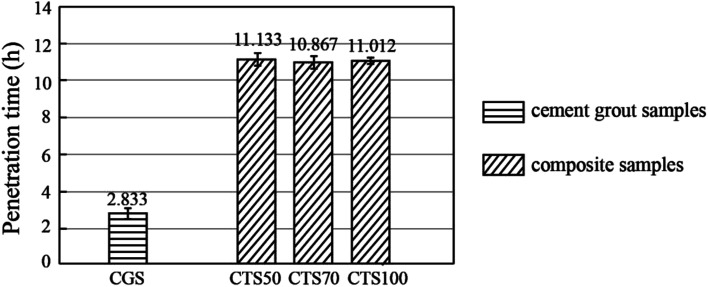
Fig. 6 presents the results of permeability experiments of the net cement grout samples and the composite samples. Water was observed on the surfaces of three net cement grout specimens after 2.4 h, 2.9 h and 3.2 h, respectively, while the corresponding impermeability pressure ranged from 0.3 to 0.4 MPa. The average permeability time and corresponding impermeability pressure of net cement grout are 2.833 h and 0.3 MPa. The slight variation of permeability time between net cement grout samples stems from instrumental errors and sampling errors, such as non-uniformity of pore distribution and difference of pore connectivity within samples, slight hydraulic pressure fluctuation during measurement and so on.
Fig. 6. Results of permeability experiments for composite specimens and control cement grout.
Compared to net cement grout, the required time for water seepage occurring on the surfaces of composite specimens with the cement–tail sealant interface was much longer. More specifically, water seepage was observed on the surface of CTS70 after 10.867 h, on average, and the corresponding impermeability pressure was 1.1 MPa. Meanwhile, water seepage occurred on the surfaces of CTS50 and CTS100 at 11.133 h and 11.012 h, respectively, and the corresponding impermeability pressure was 1.2 MPa. Much higher anti-permeability pressure and longer time period corresponding to the occurrence of water seepage on the surface confirmed the enhanced waterproofing performance of the composite samples with the cement–tail sealant interface. In addition, for three specimens with the interface, the location of interface within the composite samples had little effect on the value of impermeability pressure.
3.1.2. SWCA results
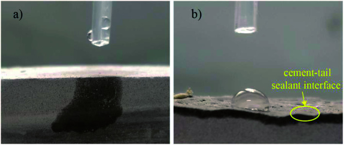
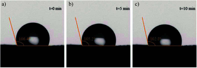
As shown in Fig. 7a, water droplets fully spread out and penetrate into cement grout, corresponding to a contact angle nearly 0°. As expected (shown in Fig. 7b), the cement–tail sealant interface sample exhibited the characteristic of hydrophobic material with a water contact angle >90°. The variation of water-contact angles of the cement–tail sealant interface over time was shown in Fig. 8. Although there was a slight decrease of water contact angle as time elapsed, all the measured contact angles are much larger than 90°. This indicates the hydrophobicity of the cement–tail sealant interface and confirms that the water wetting ability of surface of cement grout changed from hydrophilicity to hydrophobicity with the addition of modified tail sealant, which likely helped enhance waterproofing performance of the composite samples.
Fig. 7. Water wetting ability of (a) cement grout and (b) the cement–tail sealant interface specimens.
Fig. 8. Static water contact angles of the cement–tail sealant interface measured at (a) 0 min, (b) 5 min and (c) 10 min after the placement of the water drop.
3.2. Chemical bonding, microstructure and pore characteristics of cement–tail sealant interface
3.2.1. FTIR results
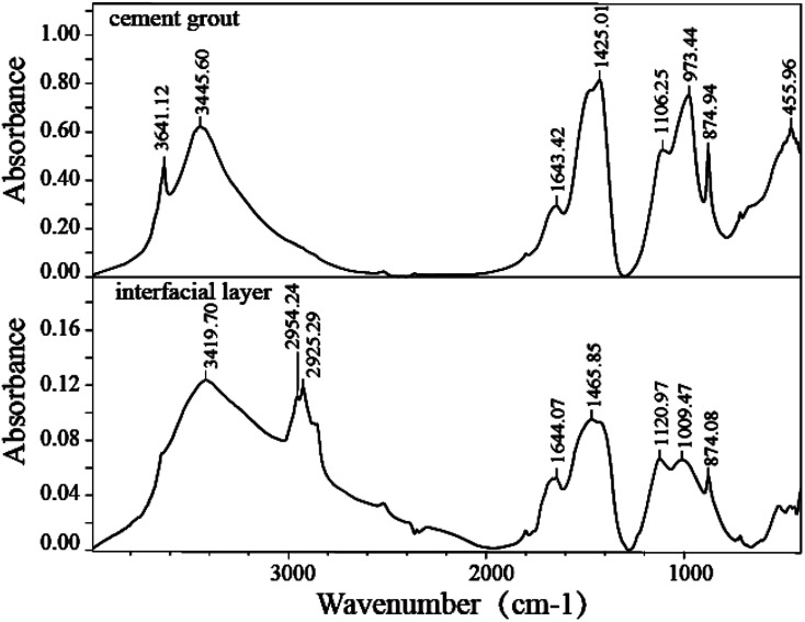
Fig. 9 presents the FTIR spectra of cement grout and the cement–tail sealant interfacial layer samples. For cement grout sample, two peaks were observed at 3445.60 cm−1 and 1643.42 cm−1 which were assigned to stretching and bending vibration of hydroxyl in free water, adsorbed water or constitutional water. The peak at wave-numbers of 3614 cm−1 was attributed to O–H of calcium hydroxide, which could be detected in the sample of cement grout as Shaheen et al. reported.44 The absorption bands at 973.44 cm−1 and 455.95 cm−1 were attributed to the presence of C–S–H, which corresponds to stretching vibration of the Si–O bond. It is observed that the bands at 1106.15 cm−1, 1425.01 cm−1 and 874.94 cm−1 correspond to vibration peaks of SO42− and CO32− respectively, which were due to unhydrated cement particles.
Fig. 9. FTIR spectra of cement grout and cement–tail sealant interface samples.
Compared with the spectra of cement grout, two new bands near 2954.24 cm−1 and 2925.29 cm−1 were observed in the cement–tail sealant interface sample and attributed to the methyl group (CH3) and methylene group (CH2), respectively, in the organic chain of MPTMS (i.e., methacryloxypropyl) and organic ingredients of conventional tail sealant, such as base oil and adhesive. The peaks at 1009.47 cm−1 and 1120.97 cm−1 were associated with Si–O–Si stretching of siloxane oligomer, which indicated the possibility of hydrolysis–condensation reaction of silane molecules. More specifically, silane molecules hydrolyze and form intermediary with one, two or three hydroxyl groups, and then dehydration condensation reaction of intermediary to form siloxane oligomer, which contains Si–O–Si chemical bond. Furthermore, absorption peak at 3641 cm−1 was visibly weaker, relative to that of cement grout sample, and the peaks of C–S–H group disappeared for cement–tail sealant interfacial layer specimen, which were likely attributed to reactions between siloxane oligomer and cement hydration products. It was likely that hydroxyl groups of siloxane oligomers formed strong hydrogen bonds with the hydroxyl groups of CH and C–S–H in cement grout, which further changed into covalent bonding during the hardening process of cement. The hydrophobicity and anti-permeability of cement–tail sealant interface modified by MPTMS were improved, which was likely caused by the covalent bond between silane coupling agent and cement based on FTIR results.
3.2.2. SEM-DEX analysis
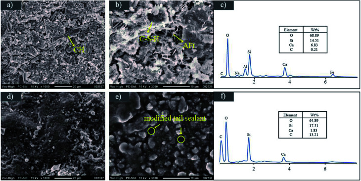
Fig. 10 shows the SEM images of cement grout and cement–tail sealant interface samples and their corresponding EDX results. In this figure, columnar CH crystals with relatively large volume, aciculate ettringite crystals and amorphous C–S–H gel and a great number of capillary pores and air voids (∼1 μm and ∼10 μm indicating the approximate diameter) could be observed in the specimen of cement grout after curing 7 days. As can be seen from corresponding EDX results (Fig. 10c), O, Si and Ca were dominant component of cement grout, and corresponding mass fraction was 68.89%, 14.51% and 6.83%, respectively. Compared to cement grout sample, the cement–tail sealant interface sample is denser and smoother, and its surface seems covered with a film of gelatinous materials, which indicated the molecules of modified tail sealant migrated into cement grout and formed hydrophobic barrier on the surface of cement to improve waterproofing performance (see Fig. 10d and e), which can be confirmed by its EDX result. In Fig. 10f, C content increased and Si and O showed a slight increase trend compared with cement grout, indicating the ingredient of modified tail sealant successfully migrated into cement grout, such as base oil, adhesive and MPTMS. Additionally, the number and the size of pores of the cement–tail sealant interface sample were apparently smaller than cement grout ones. Overall, SEM-EDX images confirm that increasing density and decreasing porosity in the interface sample also contributed to their enhanced waterproofing performance.
Fig. 10. SEM images of cement grout (a and b), cement–tail sealant interface (d and e) samples after 7 day curing and corresponding EDX images to cement grout (c) and cement–tail sealant interface (f).
3.2.3. Pore characteristics
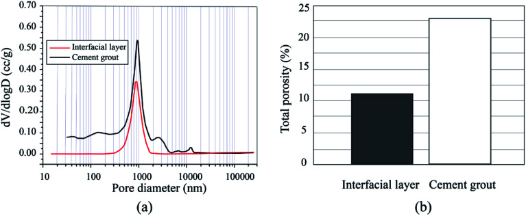
Fig. 11a shows that the total porosity of cement–tail sealant interface sample was 11.07%, which was approximately half as less as that of cement grout sample (22.87%). This is consistent with the microstructure of these sample, as shown in the section above, which indicates that waterproofing performance of cement grout was improved due to mechanical interlocking of modified tail sealant.
Fig. 11. Pore diameter distribution (a) and total porosity (b) of cement grout and cement–tail sealant interface samples from MIP tests.
Fig. 11b shows the pore size distribution of the cement grout and cement–tail sealant interface sample specimens, with pores of apparent diameters ranging from 10 nm to 20 μm. Pore type can be divided into four categories according to pore size: interlaminar pores of C–S–H (1–3 nm), capillary pores (10 nm to 1 μm) and micro-pore (1 μm to 10 μm), and air void (more than 10 μm).45–47 In Fig. 11b, a peak was observed for cement grout (w/c 0.7) with pore diameter of 1 μm, which was the diameter of dominant pores in the cement grout samples. Moreover, there were capillary pores with pore diameters from 12 nm to 1 μm and several micro-pores and air voids whose pore diameter exceeded 1 μm in specimen of cement grout. Specifically, two secondary peaks, ∼2.6 μm and ∼13 μm, can be observed in micro-pore and air void zone. Compared with cement grout, the diameter of dominant pores of the cement–tail sealant interfacial layer sample is around 0.9 μm, which is slightly smaller than that of the cement grout sample. Meanwhile, the intensity of dominant peak of the interface sample lower than that of cement grout sample, which indicates a smaller total pore volume. Additionally, capillary pores and large size pores nearly disappeared in pore size distribution curve of cement–tail sealant interfacial layer sample, which indicated the molecules of tail sealant with MPTMS covered the surface of capillary pores of cement grout to form mechanical interlocking and hydrophobic barrier effect.
Both pore size distribution and total pore volume of the samples suggest that the cement–tail sealant interface sample was denser and contained smaller size pores than the cement grout counterpart.
4. Conclusions
The current research is the first study to explore the feasibility of using the silane coupling agent to modify the interfacial layer between tail sealant and cement paste to enhance waterproofing performance of concrete lining in underground constructions. The cement–tail sealant interface modified by MPTMS was systematically characterized by a series of experiments in terms of its influence on the waterproofing of the cement–tail sealant system, and the main conclusions can be drawn as follows.
(1) Permeability testing results confirmed that composite samples with cement–tail sealant interface sandwiched between two cement grout layers achieved much better waterproofing performance, relative to the cement grout control samples.
(2) Water contact angle measurements of the cement–tail sealant interface modified by MPTMS suggest that the cement grout was transformed from hydrophilic to hydrophobic.
(3) Chemical bonding of the cement–tail sealant interface modified by MPTMS suggested that covalent bond between silane coupling agent and cement likely helped enhance waterproofing performance of cement surface.
(4) SEM images indicate that the cement–tail sealant interface modified by MPTMS was covered with a layer of dense and smooth gel, which confirmed hydrophobic barrier (i.e., denser and smoother microstructure) is formed on the cement surface to improve waterproofing performance.
(5) Enhanced waterproofing performance by cement–tail sealant interface modified by MPTMS and the change of its microstructure are also confirmed by the pore size distribution and reduced total porosity.
(6) The improvement mechanisms of waterproofing performance of cement–tail sealant interface modified by MPTMS can be attributed to (i) hydrophobic barrier effect; (ii) mechanical interlocking and (iii) covalent bond between silane coupling agent and cement.
In summary, silane coupling agent was firmed to enhance waterproofing performance of the cement–tail sealant composite. For further studies, chemical reactions between cement-modified tail sealant need more definitive results, such as X-ray photoelectron spectroscopy. In addition, the mechanical properties of the cement–sealant interface are required to be evaluated, including adhesion, environmental durability, the influence of silane coupling agent on cement hydration and so on. Lastly, such cement–sealant systems modified by silane coupling agent will have much more broad potential applications in civil engineering, such as waterproofing, stabilization of challenging soils, slurry wall, durability against corrosion, just to name a few.
Conflicts of interest
The authors declared that they have no conflicts of interest to this work.
Supplementary Material
References
- Liu F. Hou D. W. Arulrajah A. Horpibulsuk S. Enhancing behavior of large volume underground concrete structure using expansive agents. Constr. Build. Mater. 2016;114:49–55. doi: 10.1016/j.conbuildmat.2016.03.075. [DOI] [Google Scholar]
- Pusch R. Warr L. N. Knutsson S. Yang T. Condensed summary of current R&D on cementitious sealants for deep boreholes with HLW. Eng. Geol. 2017;226:192–198. [Google Scholar]
- Guo R. P. Dixon D. Chandler N. Use of numerical simulations to assess hydraulic and mechanical measurements of bentonite–sand buffer in an in-floor borehole. Eng. Geol. 2010;114:433–448. doi: 10.1016/j.enggeo.2010.06.003. [DOI] [Google Scholar]
- Shenoy A. V. Saini D. R. Nadkarni V. M. Rheograms for asphalt from single viscosity measurement. Rheol. Acta. 1982;21(3):333–339. doi: 10.1007/BF01515721. [DOI] [Google Scholar]
- Yu F. F. Xu X. Y. Lin N. B. Liu X. Y. Structural engineering of waterborne polyurethane for high performance waterproof coatings. RSC Adv. 2015;5(89):72544–72552. [Google Scholar]
- Hamza M. Ata A. Roussin A. Ground Movements Due to the Construction of Cut- and-Cover Structures and Slurry Shield Tunnel of the Cairo Metro. Tunnel. Tunnelling and Underground Space Technology. 1999;14:281–289. doi: 10.1016/S0886-7798(99)00044-9. [DOI] [Google Scholar]
- You G. M., Zhou Z. Y. and Shen Y. F., Project of the First Underwater Shied Tunnel at Jiangyin in China Advances in Underground Space Development, 2013, pp. 1080–1086 [Google Scholar]
- Jensen B. T. Faurschou M. Kasper T. A modelling approach for joint rotations of segmental concrete tunnel linings. Tunnelling and Underground Space Technology. 2017;67:61–67. doi: 10.1016/j.tust.2017.04.019. [DOI] [Google Scholar]
- Shalabi F. I. Cording E. J. Paul S. L. Concrete segment tunnel lining sealant performance under earthquake loading. Tunnelling and Underground Space Technology. 2012;31:51–60. doi: 10.1016/j.tust.2012.04.006. [DOI] [Google Scholar]
- Yoo C. Effect of water leakage in tunnel lining on structural performance of lining in subsea tunnels. Mar. Georesour. Geotechnol. 2017;35(3):305–317. doi: 10.1080/1064119X.2016.1162235. [DOI] [Google Scholar]
- Wang D. Q. Study on Water-tightness and Pumpability of Shield Tail Sealing Grease. Tunnel Construction. 2014;34(2):107–110. [Google Scholar]
- Zhou Y., Preparation method and application of environment-friendly type shield tail sealing grease, CN103865616, China, 2014 [Google Scholar]
- Wang D. Q. Formulation Research and Property Characterization of a Kind of Shield Tail Sealing Grease. Tunnel Construction. 2013;33(4):277–280. [Google Scholar]
- Wang X. G. Zhai S. T. Wang K. Xie T. Modification of bonding properties and microstructure of resin-cement interface by coupling agents. Compos. Interfaces. 2018;25(1):27–37. doi: 10.1080/09276440.2017.1323518. [DOI] [Google Scholar]
- Sang J. Aisawa S. Miura K. Hirahara H. Jan O. Jozef P. Pavol M. Adhesion of carbon steel and natural rubber by functionalized silane coupling agents. Int. J. Adhes. Adhes. 2017;72:70–74. doi: 10.1016/j.ijadhadh.2016.10.008. [DOI] [Google Scholar]
- Lu Y. H. Li X. W. Wu C. F. Xu S. A. Comparison between polyether titanate and commercial coupling agents on the properties of calcium sulfate whisker/poly(vinyl chloride) composites. J. Alloys Compd. 2018;750:197–205. doi: 10.1016/j.jallcom.2018.03.301. [DOI] [Google Scholar]
- Liu F. Hu C. Mechanical and Antibacterial Properties of Silicone Rubber Compounds Filled with Silver-Zirconium Phosphate Modified by Aluminate Coupling Agent. Polym.-Plast. Technol. Eng. 2017;56(18):1969–1976. doi: 10.1080/03602559.2017.1298796. [DOI] [Google Scholar]
- Karthick S. Park D. J. Lee Y. S. Saraswathy V. Lee H. S. Jang H. O. Choi H. J. Development of water-repellent cement mortar using silane enriched with nanomaterials. Prog. Org. Coat. 2018;125:48–60. doi: 10.1016/j.porgcoat.2018.08.021. [DOI] [Google Scholar]
- Tatar J. Torrence C. E. Mecholsky J. J. Taylor C. R. Hamilton H. R. Effects of silane surface functionalization on interfacial fracture energy and durability of adhesive bond between cement paste and epoxy. Int. J. Adhes. Adhes. 2018;84:132–142. doi: 10.1016/j.ijadhadh.2018.02.009. [DOI] [Google Scholar]
- Stewart A. Schlosser B. Douglas E. P. Surface Modification of Cured Cement Pastes by Silane Coupling Agents. ACS Appl. Mater. Interfaces. 2013;5(4):1218–1225. doi: 10.1021/am301967v. [DOI] [PubMed] [Google Scholar]
- Sudbrink B. Moradllo M. K. Hu Q. Ley M. T. Davis J. M. Materer N. Apblett A. Imaging the presence of silane coatings in concrete with micro X-ray fluorescence. Cem. Concr. Res. 2017;92:121–127. doi: 10.1016/j.cemconres.2016.11.019. [DOI] [Google Scholar]
- Kong X. M. Liu H. Lu Z. B. Wang D. M. The influence of silanes on hydration and strength development of cementitious systems. Cem. Concr. Res. 2015;67:168–178. doi: 10.1016/j.cemconres.2014.10.008. [DOI] [Google Scholar]
- Tittarelli F. Moriconi G. The effect of silane-based hydrophobic admixture on corrosion of reinforcing steel in concrete. Cem. Concr. Res. 2008;38(11):1354–1357. [Google Scholar]
- Khanzadeh Moradllo M. Sudbrink B. Ley M. T. Determining the effective service life of silane treatments in concrete bridge decks. Constr. Build. Mater. 2016;116:121–127. doi: 10.1016/j.conbuildmat.2016.04.132. [DOI] [Google Scholar]
- Xue X. Li Y. Yang Z. He Z. Dai J.-G. Xu L. Zhang W. A systematic investigation of the waterproofing performance and chloride resistance of a self-developed waterborne silane-based hydrophobic agent for mortar and concrete. Constr. Build. Mater. 2017;155:939–946. [Google Scholar]
- Rincón O. T. d. Millano V. Aboulhosn M. Morales C. Bravo J. Sánchez M. Contreras D. Hernández Y. Evaluation of Hydrophobic Concrete Coatings in Tropical Marine Environments. Corrosion. 2011;67(11):115001–115012. [Google Scholar]
- Herb H. Gerdes A. Brenner-Weiß G. Characterization of silane-based hydrophobic admixtures in concrete using TOF-MS. Cem. Concr. Res. 2015;70:77–82. [Google Scholar]
- Cai Y. Hou P. Duan C. Zhang R. Zhou Z. Cheng X. Shah S. The use of tetraethyl orthosilicate silane (TEOS) for surface-treatment of hardened cement-based materials: a comparison study with normal treatment agents. Constr. Build. Mater. 2016;117:144–151. doi: 10.1016/j.conbuildmat.2016.05.028. [DOI] [Google Scholar]
- Dąbrowski M. Glinicki M. Gibas K. Jóźwiak Niedźwiedzka D. Effects of calcareous fly ash in blended cements on chloride ions migration and strength of air entrained concrete. Constr. Build. Mater. 2016;126:1044–1053. doi: 10.1016/j.conbuildmat.2016.08.115. [DOI] [Google Scholar]
- Li B. Mao J. Nawa T. Han T. Mesoscopic damage model of concrete subjected to freeze-thaw cycles using mercury intrusion porosimetry and differential scanning calorimetry (MIP-DSC) Constr. Build. Mater. 2017;147:79–90. [Google Scholar]
- Liu S. Z., Xu P. C., Tail shield sealing grease, CN104263465, China, 2015 [Google Scholar]
- Zhou Y. S. Yu J. R. Wang X. X. Wang Y. Zhu J. Hu Z. M. Preparation of KH570-SiO2 and their modification on the MF/PVA composite membrane. Fibers Polym. 2015;16:1772–1780. [Google Scholar]
- Zhang Q. H. Jiang J. X. Gao F. Zhang G. F. Zhan X. L. Chen F. Q. Engineering high-effective antifouling polyether sulfone membrane with P(PEG-PDMS-KH570)@SiO2 nanocomposite via in situ sol-gel process. Chem. Eng. J. 2017;321:412–423. doi: 10.1016/j.cej.2017.03.105. [DOI] [Google Scholar]
- Wu G. H. Liu S. Q. Wu X. Y. Ding X. M. Influence of MWCNTs modified by silane coupling agent KH570 on the properties and structure of MWCNTs/PLA composite film. J. Polym. Res. 2016;23(8):155–163. doi: 10.1007/s10965-016-1024-3. [DOI] [Google Scholar]
- Ji C. Zhou S. H. Xu K. LI X. L. Field test research on influence factor of upward moving of shield tunnel segments during construction. Chin. J. Rock Mech. Eng. 2013;32(2):3619–3626. [Google Scholar]
- Lu G. C., Wang S. J., Zeng F. W., Gui W. X., Waterproofing membrane can cooperate with concrete by chemical and physical crosslinking, CN 101694114 A, China, 2009 [Google Scholar]
- Lu G. C., Liu R. H., Li S. Q., Cui L. B., CPS pre-paving waterproofing membrane and preparation method, CN 106883493 A, China, 2017 [Google Scholar]
- Zhu Y. Y. Hu J. Ma Y. W. Xie H. B. Guo W. H. Wei J. X. Yu Q. J. The effect of micelles with random pH-sensitive/hydrophobic structure on the workability, hydration process and microstructure of cement paste. RSC Adv. 2017;7(28):17085–17094. [Google Scholar]
- Zhao L. Guo X. L. Liu Y. Y. Ge C. Guo L. P. Shu X. Liu J. P. Synergistic effects of silica nanoparticles/polycarboxylate superplasticizer modified graphene oxide on mechanical behavior and hydration process of cement composites. RSC Adv. 2017;7(27):16688–16702. doi: 10.1039/C7RA01716B. [DOI] [Google Scholar]
- Wang P. M. Li N. Xu L. L. Hydration evolution and compressive strength of calcium sulphoaluminate cement constantly cured over the temperature range of 0 to 80 degrees C. Cem. Cem. Concr. Res. 2017;100:203–213. doi: 10.1016/j.cemconres.2017.05.025. [DOI] [Google Scholar]
- Que W. X. Kam C. Hi. Sol-gel fabrication and properties of optical channel waveguides and gratings made from composites of titania and organically modified silane. Opt. Eng. 2002;41(7):1733–1737. doi: 10.1117/1.1482098. [DOI] [Google Scholar]
- Zegaoui A. Derradji M. Ma R. Cai W. A. Medjahed A. Liu W. B. Dayo A. Q. Wang J. Silane-modified carbon fibers reinforced cyanate ester/benzoxazine resin composites: Morphological, mechanical and thermal degradation properties. Vacuum. 2018;150:12–23. [Google Scholar]
- Klein N. S. Bachmann J. Aguado A. Toralles-Carbonari B. Evaluation of the wettability of mortar component granular materials through contact angle measurements. Cem. Concr. Res. 2012;42(12):1611–1620. doi: 10.1016/j.cemconres.2012.09.001. [DOI] [Google Scholar]
- Shaheen F. Pradhan B. Influence of sulfate ion and associated cation type on steel reinforcement corrosion in concrete powder aqueous solution in the presence of chloride ions. Cem. Concr. Res. 2017;91:73–86. doi: 10.1016/j.cemconres.2016.10.008. [DOI] [Google Scholar]
- Mehta P. K., Concrete: Microstructure, Properties, and Materials, McGraw-Hill Education, 2006 [Google Scholar]
- Head M. K. Buenfeld N. R. Confocal imaging of porosity in hardened concrete. Cem. Concr. Res. 2006;36(5):896–911. doi: 10.1016/j.cemconres.2005.06.006. [DOI] [Google Scholar]
- Wang D. Yang P. Hou P. Zhang L. Zhou Z. Cheng X. Effect of SiO2 oligomers on water absorption of cementitious materials. Cem. Concr. Res. 2016;87:22–30. doi: 10.1016/j.cemconres.2016.05.005. [DOI] [Google Scholar]


