

Abstract
This work presents a wrinkled Platinum (wPt) strain sensor with tunable strain sensitivity for applications in wearable health monitoring. These stretchable sensors show a dynamic range of up to 185% strain and gauge factor (GF) of 42. This is believed to be the highest reported GF of any metal thin film strain sensor over a physiologically relevant dynamic range to date. Importantly, sensitivity and dynamic range are tunable to the application by adjusting wPt film thickness. Performance is reliable over 1000 cycles with low hysteresis after sensor conditioning. The possibility of using such a sensor for real-time respiratory monitoring by measuring chest wall displacement and correlating with lung volume is demonstrated.
1. Introduction
Advances in mobile health (mHealth) monitoring have been stymied by a lack of available conformal sensors.1–3 Wearable devices have seen some early success by packaging standard and/or flexible electronics to be adorned as “smart” fashion accessories for consumers. However, such sensor technology remains unable to produce accurate, quantitative biometric data to be usable for many mHealth applications.1,4
One of the most common sensors currently utilized is the tri-axial accelerometer. Many studies have focused on clever placement of these sensors and sophisticated algorithms to classify or analyze gait,5 respiration,6 and even fetal movement.7 However, discernment of precision movement and extraction of signal from noise remains challenging with accelerometers alone. 1,8 For this reason, biometric data from an abundance of commercially available wearable devices are often reduced to less specific quantitative measurements such as “activity.”1,8,9
Strain sensors are a promising addition to accelerometers for wearable applications. Strain can be used to determine pressure,10–12 displacement,13,14 bending angle,15,16 and acoustic vibrations.12,17 These metrics can be combined to establish quantitative measures for monitoring human movement as it relates to athletic performance,18 rehabilitation,19 or physical symptoms from drugs or illnesses.1 With this goal in mind the rapidly maturing field of flexible electronics has made tremendous strides towards developing new, mechanically compliant transducers in order to enable wearable devices to unobtrusively acquire biometric signals.20–23 As such, wearable strain sensor development has seen research focused towards stretchable capacitive, percolating, and piezoresistive (PR) sensor types.
Capacitive sensors utilize compression of the dielectric layer, which is caused by either normal pressure or Poisson ratio changes from in-plane strains. These types of sensors can exhibit excellent sensitivity for detecting subtle movements such as pulsatile pressure.11,24 Li et al. developed a wearable pressure sensor on flexible PET film with transparent ITO electrodes and ionic gel dielectric. By integrating into a low profile cuff, they show the potential for effective monitoring of chronic venous disease using capacitive pressure sensors.11 However, with parallel ITO electrodes on PET films this device is flexible but not stretchable to cope large strains. Larger strains such as those required to measure gross body movements are also attainable using capacitive strain sensing. Zens et al. demonstrates this using interdigitated electrodes on elastic silicone to quantify knee laxation for post-operative rehabilitation monitoring.15 Although the dynamic range for strain is often sufficient for the intended application, these sensors can suffer from poor sensitivity, gauge factors (GF) <1, or capacitive interactions with the body which limit direct epidermal application.16
Percolation strain sensors are often thin composite materials containing conductive networks of micro/nano particles. When stretched or compressed, the relative density and/or degree of contact of these conductive networks change, reflected in change in resistance. Percolating sensors can also be optimized for either small or large strains. Gong et al. demonstrated pulse detection by placing a percolating network of gold nanowires over an interdigitated electrode pattern on a PDMS substrate.12 Pan et al. has shown through rationally designed conductive polypyrrole (PPy) hydrogels25,26, high sensitivity at ultra-low pressures (<1Pa) and a medium pressure saturation threshold (~100 kPa) is possible.27 Importantly, the use of the hydrogel reduces viscoelastic effects when compared to other elastic polymers, however, rapid aging of the PPy in air causes electronic drift and thus relies on effective device packaging. Dense networks of carbon nanotubes (CNT) can be used to measure larger strains in part due to their high electrical conductivity and robust mechanical properties. Amjadi et al. demonstrate the ability to measure joint flexion with such CNT devices, which can record strains in excess of 60%.16 Although many of these sensors show good linear response with low hysteresis over very large strains (>1000%),28 it is often at the expense of sensitivity (GF < 1).16,28,29 Moreover, sensitivity in percolating type sensors can be very high, but at the tradeoff of a limited dynamic range; this necessitates more complex architectures to achieve both high GF and a large dynamic range.14,27
Wearable PR sensors often employ thin conductive materials that exhibit resistance-strain dependence primarily from geometric changes and controlled fracturing or crack propagation in the sensing film upon applied strain.10 This leads to a tremendous amount of tunability in both sensitivity and dynamic range with lithographically defined geometries30,31 and materials choices.13,17,31–34 Very high sensitivity can be achieved, as demonstrated by Kang et al., by utilizing relatively brittle platinum (Pt) thin films to detect sound vibrations for word recognition with a GF > 2000 and a dynamic range of 2% strain.17 Recently, Yong et al. produced wrinkled graphene PR strain gauges with a modest GF of ~2.8 and dynamic range of 100% strain.35 Large dynamic range (>100%) is possible using alternate materials, however, often yielding low strain sensitivity.36–38
Here we introduce hierarchical wrinkled structures into Pt thin films (wPt) which perform as PR strain sensors. These micro-nanowrinkles in the wPt thin film, supported on skin-like silicone rubber, enhance the dynamic range (>100% strain) while also attaining good sensitivity that is inherent to Pt thin films (GF = 42 at 185% strain). The GF was taken at 185% strain because for nonlinear sensitivity curves, the GF at the highest strain is often reported.13,39,40 To our knowledge this represents the highest GF over a large, and physiologically relevant, range of any metal thin film strain sensor.31,36,41,42 Tunable sensitivity and dynamic range is achieved by changing wPt film thickness. We demonstrate the potential of this sensor in mHealth monitoring by quantifying lung volume correlated to chest wall displacement during respiration. Further, this wPt sensor can be lithographically defined using standard semiconductor equipment and materials. Therefore, these sensors can be optimized for many wearable applications and scaled to production with roll-to-roll processing.43
2. Experimental
2.1. Fabrication of wPt strain sensors
Sensor designs are drawn using computer aided design software (Autodesk). The sensor design is laser machined (Versa Laser, VLS2.30) into a single-sided adhesive polymer film (Grafix Arts, Frisket Film) to create a mask. This mask is adhered to a pre-stressed polystyrene (PS) film (Grafix Arts, KFS50-C). A 5 nm Pt thin film is deposited onto the masked PS film using a timed magnetron sputter deposition (Quorum Technologies, Q150R) of 207 s. For 25 nm and 50 nm thick Pt films, samples are sputtered for 1057 s and 2124 s, respectively. A second layer of 5 nm Au is sputter deposited (102 s) onto the Pt thin film. The mask is then lifted off the PS film, leaving the desired metal thin film sensor design (Figure 1). The sample is subsequently placed into a convection oven at 160°C for 5 minutes to induce the thermal miniaturization process. The sensor design is shrunk to 33% of its original size, creating wrinkles in the metal thin film, which, as previously shown, reduces resistivity44. An adhesion promotor is used to reliably transfer the wPt and Au thin film to EF30 (Smooth-on, Ecoflex 0030). The shrunken sample is placed in a 5mM (3-Mercaptopropyl) trimethoxysilane (Sigma Aldrich, 95% MPTMS) in ethanol bath for 1 hr before air drying. EF30 is poured immediately onto the MPTMS treated samples and spin coated at 150 rpm for 35 s. Following spin coating, samples are placed under vacuum for 20 min and then removed to cure at 85 °C for 2 hrs. The wPt thin film is then transferred onto EF30 by lifting off the PS layer in an acetone bath for 30 min at 75 °C. Once the PS layer has lifted off, the samples are dipped in a toluene bath and immediately washed with acetone. This final wash process is repeated as necessary to ensure removal of all residual PS from the wPt thin film. Finally, the strain sensors are left dry in a fume hood for 1 hr.
Figure 1.

shows (A, left to right) as deposited, wrinkled, and transferred wPt strain sensors with a US dime for scale and (B) an illustration of the fabrication process flow.
2.2. Sheet resistance
Measurements were taken with a four-point probe station combined with a rapid source measuring unit (Keithley, 2612B Source Meter). The voltage was set to 100mV, and the resulting current was measured. The Van der Pauw method was then used to determine the sheet resistance value. Separate samples were prepared with 3 nm of Ir for visualization using SEM (FEI, Magellan).
2.3. Strain characterization
Strain sensitivity of wPt sensors was determined using a semi-static tensile strain testing apparatus. Resistance is recorded at 5% strain increments until failure. Additionally, sensors pre-conditioned at 100% strain were subjected to subsequent cyclic fatigue testing by straining sensors from 0% to 50% using a saw-tooth waveform on a computer controlled linear strain testing apparatus. The samples were cycled 1000 times at 4mm/s.
Response time was measured by rapidly (13.6 mm/s) tensioning the sensor to 50% strain and holding for 10 s. The sample was then released at the same rate back to 0% strain and held for 10 s before beginning the next cycle. Response and relaxation time is reported from the tenth cycle.
2.4. FEA modeling conditions
A simplified 2D finite element analysis (FEA) was performed using Ansys workbench 16.0. A cross sectional geometry was created with hierarchal wrinkle structures; the model consists of two metallic thin film of Au and Pt on top of an EF30 substrate. The Au and Pt were modeled as isotropic elastic material with Young’s modulus of 69.1 GPa and 139.7 GPa, respectively.45 The EF30 was modeled with a two parameter Mooney-Rivlin hyperelastic model.46 The finite element analysis was performed with 50 and 100 percent strain.
2.5. FFT parameters
To find the wavelength distribution of the wrinkles, a 2D Fast Fourier Transform (2D FFT) was applied to a sectioned top down SEM image of the sensor surface. The absolute value of the 2D FFT output was readjusted such that the zero wavenumber, defined as 1/wavelength, started at the center and the largest wavelength ended on the edge. The intensity values were then summed radially for each wavenumber to create an intensity versus wavelength profile. Afterwards, the intensity was adjusted for noise by subtracting the total background noise at each summation, and the profile was normalized to the largest intensity value. Lastly, only the relevant range of wrinkle wavelength was graphed as intensity versus wavenumber.
2.6. Chest wall displacement sensor setup
Finished wPt sensors were attached to athletic tape (KT Tape, cotton sports tape) and applied across the subject’s external intercostal muscles. Lung volume dynamics were measured using a digital spirometer (Contec, SP10) and were correlated to characteristic chest displacement signals as measured by the wPt sensor. Resistance changes in the sensors undergoing strain during respiration were converted to voltages using a type-1, quarter-bridge configuration Wheatstone circuit and a low-gain differential amplifier. These voltages were acquired at 40 Hz by a small 10-bit microcontroller (Atmel Corp., ATmega328) and then transmitted via Bluetooth 4.0 to a real-time monitoring application.
3. Results and discussion
3.1. ‘Shrink’ fabrication and transfer
Stiff thin film materials buckle and form complex hierarchical wrinkles in response to compressive stress of shape-memory polymer (SMP) carrier films.47 These wrinkled structures have proven useful for increasing sensitivity and/or efficiency of electrochemical,48 optical scattering,49 SERS,50,51 and various other sensors.52–54 Often, wrinkled thin film structures robustly integrate with the SMP carrier films using the aforementioned processing techniques, limiting the final device material to a rigid thermoplastic. Transferring the wrinkled thin film onto other materials allows for the same enhancements provided by the hierarchical wrinkled thin films to apply towards applications unsuitable for rigid SMPs. This is especially the case with wearable sensors and mHealth, where a device is conformable to curvilinear surfaces and mechanically similar to human skin. The method demonstrated in this work builds on previous shrink fabrication methods by introducing a SMP lift-off and transfer of PR wPt thin films onto biocompatible EF30 elastomeric silicone (Figure 1). This silicone supported wPt serves as a skin-mountable strain sensor with potential for use as a wearable mHealth monitor.
The Pt thin film is sputter deposited through a physical mask onto a polystyrene (PS) SMP support film similar to previously reported works.38,48 Three Pt film thicknesses where tested: 5, 25, and 50 nm. A 5 nm thin film of Au is then deposited in order to strongly adhere the thin film to EF30 using (3-Mercaptopropyl) trimethoxysilane (MPTMS) chemistry55 upon transfer. Prior to MPTMS treatment the patterned thin film on SMP is thermally shrunken by 67% in area to create the wPt thin film. Then MPTMS is linked to the Au film and uncured EF30 is molded on top. Once the EF30 has cured, the PS support is lifted-off using organic solvents. This leaves the wPt thin film, now supported on skin-like EF30 (Figure 1B).
3.2. Tunable strain sensors
Sheet resistance was compared between as deposited, wrinkled, and transferred thin films (Table S1). Sheet resistance decreases substantially upon thermal shrinking of the as deposited thin films. This effect has been previously studied, in brief bi-axial compression of thin films bridges discontinuities in as deposited thin films whereby lowering electrical resistivity.48,56 Sheet resistance increases between wrinkled and transferred thin films. However, transferred thin film sheet resistances remain ~65% lower than those of their as deposited precursors. Sheet resistance for 5, 25, and 50 nm wPt thin films are 1243, 1070, 1031 Ω/□ respectively. This suggests that the transfer process maintains good integrity of the wPt. Moreover, during fabrication of the wPt strain sensors, an Au thin film and MPTMS treatment is used to irreversibly adhere the piezoresistive Pt thin film to EF30. Therefore, sheet resistance measurements reflect the Pt and Au bimetallic layer. Importantly, sheet resistance measured before the wPt is transferred onto silicone have probes contacting the Au surface whereas probes contact the wPt when measuring sheet resistance after the transfer. Indeed, visualization under SEM further suggests good integrity of the wPt thin film to also preserve the complex hierarchical structure (Figure 2A) after transfer.
Figure 2.
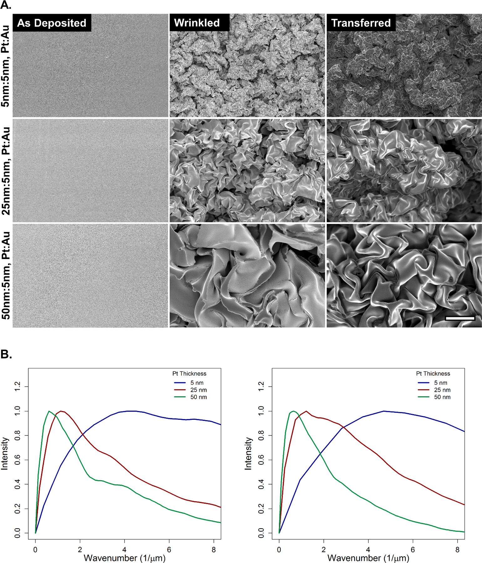
shows (A) SEM of as deposited, wrinkled, and transferred Pt thin films at 5, 25, and 50 nm. All micrographs are at equivalent magnification. Scale bar is 5 µm. (B) shows FFT performed on wrinkled (left) and transferred (right) SEM showing the frequency of different length scale features.
Feature size of the wPt increases with film thickness (Figure 2B). This results in a decreased density of wrinkling and increased fracturing of the brittle Pt thin film prior to transfer as film thickness increases. We theorize that the density of the wrinkles plays a vital role in the controlled fracture of the wPt sensor, affecting both dynamic range and GF as will be discussed in the following section. The dynamic range of wPt strain sensor can be tuned according to film thickness as shown in semi-static linear strain tests with 5, 25, and 50 nm thin film sensors (Figure 3A). Multiple sensors of each film were tested (Figure S1) and the best performing are represented in Figure 3A.
Figure 3.
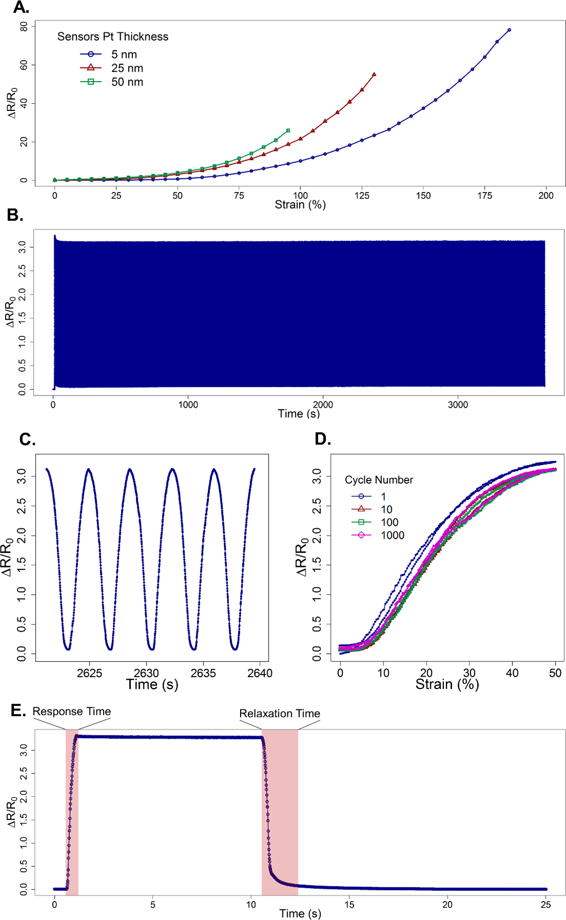
shows (A) the strain sensitivity of the best performing 5, 25, and 50 nm wPt strain sensors. (B) 5 nm wPt sensors underwent 1000 cycles of a tensile strain for durability testing. The samples were preconditioned at 100% strain, then subsequently cycled continuously at 50% strain at 4 mm/s. (C) shows a small subset of strain cycling to show the repeatability and stability of the sensor. (D) plots select tensile and relaxation cycles of percent resistance change vs. strain which shows a very brief conditioning phase followed by consistent performance with low amounts of hysteresis. (E) Shows a sensor rapidly strained to 50% and held for 10 s before rapidly returning to 0% strain in order to quantify response and relaxation time. Due to viscoelastic properties present in the processed EF30 polymer relaxation time are elongated as compared to the speedy response time.
Thinner wPt thin films demonstrate the highest dynamic range with maximum strains as high as 185%. We theorize this is due to a combination of both more malleable mechanical properties of the 5 nm Au thin film and a higher density of wrinkles. As the Pt film thickness increases, the mechanical behavior is ever dominated by the comparatively brittle wPt. This results in more fractures prior to strain and most importantly a lower density of nano/microwrinkles in the thicker 25 and 50 nm wPt films. Lower density in wrinkles results in less stress relief in the wPt thin film as will be discussed in greater detail in the following section. Strain sensitivity therefore increases in these thicker samples yielding higher GF at lower strains when compared to thin films with higher wrinkle densities. At equivalent strain, 50 nm thick wPt displays the highest GF of 27 at 95% strain whereas 25 nm and 5 nm thin films show lower GF of 20 and 9, respectively. However, the 5 nm wPt sensor achieves the absolute highest GF of 42 at 185% strain.
Durability of 5 nm wPt samples was also studied, applying multiple tensile cycles to 50% strain at 4 mm/s (Figure 3B) for 1000 cycles. These samples were first conditioned by being stretching out to 100% strain (data not shown) before beginning cycled continuously at 50%. During repeated straining the sensor still shows a brief conditioning phase in the first few cycles. However, when the sensor becomes conditioned after multiple cycles, hysteresis is significantly reduced and the sensor performance is stable through the end of the test. The sensor displays excellent reproducibility with little to no change in hysteresis between cycle 10, 100 and 1000 (Figure 3D). Important to note that unlike the semi-static linear strain testing (Figure 3A), sensor response to strain cycling (Figure 3D) is rate dependent. Sensors where cycled as many as 6500 times without failure or apparent delamination of thw wPt from the EF30 support film (Figure S3).
Sensor response time of 0.5 s shows no latency from the time required to actuate the sensor on the test fixture and the sensor reading within 10% of the sensor saturation value (Figure 3E). Increasing the response time criteria to within 1% of saturation increases response time to 0.6 s representing a latency of 0.1 s. However, relaxation time suffers from the viscoelastic effects of the processed EF30. Because organic solvents were used during the lift off process, the EF30 appears to suffer from rapid aging where by increasing the viscoelastic effect upon relaxation from tensile straining. Therefore, relaxation time is elongated to 1.3 s to reach a value within 10% of baseline value, representing a latency of 0.8 s. However, stricter criteria to reach within 1% of baseline resistance increase response time dramatically to 7.6 s, a 7.1 s latency. This also accounts for some of the hysteresis seen when performing repeated tensile cycle testing. Better response times and lower hysteresis can be achieved by transferring wPt thin films onto polymers with higher chemical resistance to organic solvents and / or shorter elastic response times.
3.3. Mechanism for tunable stretch sensitivity
We theorize that the PR response to strain of the wPt thin films contains multiple phases, which result in the non-linear strain sensitivity. There are three primary phases: in-plane elongation, fracture nucleation, and fracture elongation. Resistance changes during in-plane elongation is primarily due to separation of adjacent wrinkle structures and lengthening of the geometry. Strain sensitivity increases with the fracture nucleation phase at moderate to high strain, and sensitivity increases rapidly as those fractures begin to elongate near maximum strain. A finite element model (FEM) of a hierarchical bimetallic thin film with simplified geometry was used to better understand the controlled fracturing of the wPt sensor (Figure S2). Concentration of stress is similar to results previously reported by other groups employing 2D fractal serpentine structures.30,37 As the model suggests, stress is concentrated at the high angle bend, or valleys of the thin film. This is where micro-cracking nucleates at high strains (Figure S2). Therefore, with increased density of wrinkles in the thin film, the nucleation phase for fracturing is distributed over a longer range of strain as each new fracture point relieves stress in the thin film. Therefore, increase wrinkle densities provides more strain relief in wPt thin films, increasing the strain sensor range. These multiple points of fracturing also forms a mesh-like structure in the thin film. As strain increases, the fracture nucleation points in the wrinkle valleys are exhausted. These fractures then begin to elongate, coalescing with adjacent fractures in the thin film mesh until the thin film ruptures completely. This behavior is similar to other mesh patterned Au thin film.31 Thicker thin films have a lower density of fracture nucleation sites as a result of the larger wrinkled pattern. The elongation phase, therefore, begins at lower strains and results in higher strain sensitivity.
It is important to note that this order of events for fracturing thin films is only possible through strong adhesion between the thin film and the elastic support material. Research has shown that polymer material plays an important role in evenly distributing stress throughout a thin film.42,57–59 Therefore, the Au and MPTMS adhesion layer is important for repeatable fracturing behavior. Without an adhesion layer, wPt delaminates from EF30 under minimal strain. This concentrates stress in that delamination area and causes premature failure.41,42 Unlike previous works that demonstrate the importance of strong adhesion to polymer stubstrate with Au films,31,38,57–59 the use of wPt, which is relatively brittle by comparison, in this work exhibits increased sensitivity to strain.
3.4. Monitoring respiration
A 5 nm wPt sensor was placed onto the left external intercostal muscles of the chest wall (Figure 4) with adhesive tape to measure chest wall displacement during respiration. This region was selected because of its characteristic displacement during the breathing cycle caused by the contraction and relaxation of underlying inspiratory muscles.60–62 A spirometer was used in conjunction with the wPt sensor in order to correlate inspiration capacity (IC) and tidal volume (TV) with sensor displacement (Figure 4D). The spirometric measurements showed the subject was able to expel 95% of his IC, calculated by the digital spirometer based on the subject’s physical build (height and weight). The subject followed this maximal exhale with normal tidal breathing. The wPt sensor’s strain amplitudes corresponding to the spirometric tests were correlated with the measured IC volume, producing a lung volume metric approximated by chest wall displacement. Strain sensor measurements show that the subject’s TV (small peaks following the maximal peak) is approximately 600 mL and the IRC is 3500 mL, both well within the subject’s expected physiological range. Evidence of hysteresis in the sensor is apparent however, since strain amplitudes are slow in returning to baseline readings. Adjustments can be made in future designs to reduce offset by utilizing a more responsive polymer support for the wPt thin film.
Figure 4.

shows (A.) shows (A.) a wPt strain sensor contacting a conductive flex cable and placed on stretchable athletic tape. This sensor was place on (B.) the intercostal muscles in order to measure chest wall displacement during respiration. The sensor was connected via the flex cable to a prototype board (not shown) with Bluetooth connectivity in order to transmit and log data on a computer. (C.) shows the signal from the sensor resulting from chest wall displacement during respiration. Using spirometer readings, (D.) approximate lung volumes where correlated to sensor data. *spirometer reading show inhale and exhale as reaching 95% of IC. **volumes calculated based on subject’s physical parameters.
4. Conclusion
We have presented a wPt thin film sensor capable of measuring strain as high as 185% with a high GF of 42. These sensors can be tuned for different dynamic ranges and sensitivities as required by the application. Furthermore, we demonstrate the potential of such a wearable sensor for mHealth applications by indirectly measuring lung volumes during respiration. Future development of the sensor will focus on incorporating a more responsive polymer support for the wPt thin film to increase relaxation times and reduce hysteresis. Development of classification algorithms for distinguishing between various physical states (i.e. exercise and rest) based on sensor readings will also be incorporated in an effort to automate classification and analysis of human movement.
Supplementary Material
Acknowledgements
This work was funded in part by the National Institute of Health (NIH) Director’s New Innovator Award (award number OD007283–01), National Science Foundation and the industrial members of the Center for Advanced Design and Manufacturing of Integrated Microfluidics (NSF CADMIM award number IIP-1362165. The authors thank Dr. Allon Hochbaum for allowing us the generous use of his equipment for acquiring the sheet resistance measurements.
Footnotes
Electronic Supplementary Information (ESI) available: [details of any supplementary information available should be included here]. See DOI: 10.1039/x0xx00000x
Notes and references
- 1.Dobkin BH, Curr. Opin. Neurol, 2013, 26, 602–8. [DOI] [PMC free article] [PubMed] [Google Scholar]
- 2.Takei K, Honda W, Harada S, Arie T and Akita S, Adv. Healthc. Mater, 2015, 487–500. [DOI] [PubMed] [Google Scholar]
- 3.Pantelopoulos A and Bourbakis NG, IEEE Trans. Syst. man, Cybern. part C, 2010, 40, 1–12. [Google Scholar]
- 4.Chan M, Estève D, Fourniols J, Escriba C and Campo E, Artif. Intell. Med, 2012, 56, 137–156. [DOI] [PubMed] [Google Scholar]
- 5.Hsu Y-L, Chung P-C, Wei-Hsin W, Pai M-C, Chun-Yao W, Lin C-W, Hao-Li W and Jeen-Shing W, IEEE J. Biomed. Heal. informatics, 2014, 18, 1822–1830. [DOI] [PubMed] [Google Scholar]
- 6.Dieffenderfer JP, Goodell H, Beppler E, Jayakumar R, Jur JS and Bozkurt A, in IEEE Body Sensor Networks, 2015, pp. 1–6. [Google Scholar]
- 7.Boashash B, Khlif MS, Ben-Jabeur T, East CE and Colditz PB, Digit. Signal Process, 2014, 25, 134–155. [Google Scholar]
- 8.Yang C-C and Hsu Y-L, Sensors (Basel), 2010, 10, 7772–88. [DOI] [PMC free article] [PubMed] [Google Scholar]
- 9.Mukhopadhyay SC, IEEE Sensors, 2015, 15, 1321–1330. [Google Scholar]
- 10.Liu X, Zhu Y, Nomani MW, Wen X, Hsia T-Y and Koley G, J. Micromechanics Microengineering, 2013, 23, 025022. [Google Scholar]
- 11.Li R, Nie B, Zhai C, Cao J, Pan J, Chi Y-W and Pan T, Ann. Biomed. Eng, 2015. [DOI] [PubMed] [Google Scholar]
- 12.Gong S, Schwalb W, Wang Y, Chen Y, Tang Y, Si J, Shirinzadeh B and Cheng W, Nat. Commun, 2014, 5, 1–8. [DOI] [PubMed] [Google Scholar]
- 13.Wang Y, Wang L, Yang T, Li X, Zang X, Zhu M, Wang K, Wu D and Zhu H, Adv. Funct. Mater, 2014, 24, 4666–4670. [Google Scholar]
- 14.Lu N, Lu C, Yang S and Rogers J, Adv. Funct. Mater, 2012, 22, 4044–4050. [Google Scholar]
- 15.Zens M, Niemeyer P, Bernstein A, Feucht MJ, Kühle J, Südkamp NP, Woias P and Mayr HO, Knee surgery, Sport. Traumatol. Arthrosc, 2015, 23, 2868–75. [DOI] [PubMed] [Google Scholar]
- 16.Amjadi M, Yoon YJ and Park I, Nanotechnology, 26, 375501. [DOI] [PubMed] [Google Scholar]
- 17.Kang D, V Pikhitsa P, Choi YW, Lee C, Shin SS, Piao L, Park B, Suh K-Y, Kim T and Choi M, Nature, 2014, 516, 222–6. [DOI] [PubMed] [Google Scholar]
- 18.Li RT, Kling SR, Salata MJ, Cupp S. a., Sheehan J and Voos JE, Sport. Heal. A Multidiscip. Approach, 2015, 2016. [DOI] [PMC free article] [PubMed] [Google Scholar]
- 19.Patel S, Park H, Bonato P, Chan L and Rodgers M, J. Neuroeng. Rehabil, 2012, 9, 1–17. [DOI] [PMC free article] [PubMed] [Google Scholar]
- 20.Cong H and Pan T, Adv. Funct. Mater, 2008, 18, 1912–1921. [Google Scholar]
- 21.Zhang R, Moon K, Lin W, Agar JC and Wong C, Compos. Sci. Technol, 2011, 71, 528–534. [Google Scholar]
- 22.Madaria AR, Kumar A, Ishikawa FN and Zhou C, Nano Res, 2010, 564–573. [Google Scholar]
- 23.Van Den Brand J, De Kok M, Koetse M, Cauwe M, Verplancke R, Bossuyt F, Jablonski M and Vanfleteren J, Solid State Electron, 2015, 113, 116–120. [Google Scholar]
- 24.Nie Z, a Nijhuis C, Gong J, Chen X, Kumachev A, Martinez AW, Narovlyansky M and Whitesides GM, Lab Chip, 2010, 10, 477–83. [DOI] [PMC free article] [PubMed] [Google Scholar]
- 25.Li L, Shi Y, Pan L, Shi Y and Yu G, J. Mater. Chem. B, 2015, 3, 2920–2930. [DOI] [PubMed] [Google Scholar]
- 26.Li L, Wang Y, Pan L, Shi Y, Cheng W, Shi Y and Yu G, Nano Lett, 2015, 15, 1146–51. [DOI] [PubMed] [Google Scholar]
- 27.Pan L, Chortos A, Yu G, Wang Y, Isaacson S, Allen R, Shi Y, Dauskardt R and Bao Z, Nat. Commun, 2014, 5, 3002. [DOI] [PubMed] [Google Scholar]
- 28.Ryu S, Lee P, Chou JB, Xu R, Zhao R, Hart AJ and Kim S, ACS Nano, 2015, 5929–5936. [DOI] [PubMed] [Google Scholar]
- 29.Yamada T, Hayamizu Y, Yamamoto Y, Yomogida Y, Izadi-Najafabadi A, Futaba DN and Hata K, Nat. Nanotechnol, 2011, 6, 296–301. [DOI] [PubMed] [Google Scholar]
- 30.a Fan J, Yeo W-H, Su Y, Hattori Y, Lee W, Jung S-Y, Zhang Y, Liu Z, Cheng H, Falgout L, Bajema M, Coleman T, Gregoire D, Larsen RJ, Huang Y and a Rogers J, Nat. Commun, 2014, 5, 3266. [DOI] [PubMed] [Google Scholar]
- 31.Guo CF, Sun T, Liu Q, Suo Z and Ren Z, Nat. Commun, 2014, 5, 3121. [DOI] [PubMed] [Google Scholar]
- 32.Li M, Li H, Zhong W, Zhao Q and Wang D, ACS Appl. Mater. Interfaces, 2013. [DOI] [PubMed] [Google Scholar]
- 33.Liao X, Liao Q, Yan X, Liang Q, Si H, Li M, Wu H, Cao S and Zhang Y, Adv. Funct. Mater, 2015, 25, 2395–2401. [Google Scholar]
- 34.Wang Y, Yang R, Shi Z, Zhang L, Zhi D, Wang E and Zhang G, ACS Nano, 2011, 5, 3645–3650. [DOI] [PubMed] [Google Scholar]
- 35.Yong K, Ashraf A, Kang P and Nam S, Sci. Rep, 2016, 6, 24890. [DOI] [PMC free article] [PubMed] [Google Scholar]
- 36.Arafat Y, Dutta I and Panat R, Appl. Phys. Lett, 2015, 107, 081906. [Google Scholar]
- 37.Hsu Y, Gonzalez M, Bossuyt F, Vanfleteren J, De Wolf I and Member S, IEEE Trans. Electron Devices, 2011, 58, 2680–2688. [Google Scholar]
- 38.Kim J, Park S, Nguyen T, Chu M, Pegan JD and Khine M, Appl. Phys. Lett, 2016. [DOI] [PMC free article] [PubMed] [Google Scholar]
- 39.Yan C, Wang J, Kang W, Cui M, Wang X, Foo CY, Chee KJ and Lee PS, Adv. Mater, 2014, 26, 2022–7. [DOI] [PubMed] [Google Scholar]
- 40.Kuang J, Liu L, Gao Y, Zhou D, Chen Z, Han B and Zhang Z, Nanoscale, 2013, 5, 12171–7. [DOI] [PubMed] [Google Scholar]
- 41.Lu N, Suo Z and Vlassak JJ, Acta Mater, 2010, 58, 1679–1687. [Google Scholar]
- 42.Lu N, Wang X, Suo Z and Vlassak J, Appl. Phys. Lett, 2007, 91, 221909. [Google Scholar]
- 43.Nokes JM, Liedert R, Kim MY, Siddiqui A, Chu M, Lee EK and Khine M, Adv. Healthc. Mater, 2016, 1–9. [DOI] [PMC free article] [PubMed] [Google Scholar]
- 44.Jayadev S, Pegan J, Dyer D, McLane J, Lim J and Khine M, Smart Mater. Struct, 2013, 22, 014014. [Google Scholar]
- 45.Salvadori MC, Brown IG, Vaz a. R., Melo LL and Cattani M, Phys. Rev. B, 2003, 67, 153404. [Google Scholar]
- 46.Huang Y, Wang Y, Xiao L, Liu H, Dong W and Yin Z, Lab Chip, 2014, 14, 4205–12. [DOI] [PubMed] [Google Scholar]
- 47.Lin S, Lee EK, Nguyen N and Khine M, Lab Chip, 2014, 14, 3475–88. [DOI] [PMC free article] [PubMed] [Google Scholar]
- 48.Pegan JD, Ho AY, Bachman M and Khine M, Lab Chip, 2013, 13, 4205–9. [DOI] [PubMed] [Google Scholar]
- 49.Lin S, Sharma H and Khine M, Adv. Opt. Mater, 2013, 1, 568–572. [Google Scholar]
- 50.Liu H, Zhang L, Lang X, Yamaguchi Y, Iwasaki H, Inouye Y, Xue Q and Chen M, Sci. Rep, 2011, 1, 112. [DOI] [PMC free article] [PubMed] [Google Scholar]
- 51.Zhang L, Lang X, Hirata A and Chen M, ACS Nano, 2011, 4407–4413. [DOI] [PubMed] [Google Scholar]
- 52.Sharma H, Wood JB, Lin S, Corn RM and Khine M, Langmuir, 2014, 30, 10979–83. [DOI] [PMC free article] [PubMed] [Google Scholar]
- 53.McLane J, Wu C and Khine M, Adv. Mater. Interfaces, 2015, 2. [Google Scholar]
- 54.Woo SM, Gabardo CM and Soleymani L, Anal. Bioanal. Chem, 2014, 86, 12341–12347. [DOI] [PubMed] [Google Scholar]
- 55.Byun I, Coleman AW and Kim B, J. Micromechanics Microengineering, 2013, 23, 085016. [Google Scholar]
- 56.Gabardo CM, Zhu Y, Soleymani L and Moran-Mirabal JM, Adv. Funct. Mater, 2013, n/a–n/a. [Google Scholar]
- 57.Li T, Huang Z, Suo Z, Lacour SP and Wagner S, Appl. Phys. Lett, 2004, 85, 3435. [Google Scholar]
- 58.Lacour SP, Chan D, Wagner S, Li T and Suo Z, Appl. Phys. Lett, 2006, 88, 204103. [Google Scholar]
- 59.Li T, Huang ZY, Xi ZC, Lacour SP, Wagner S and Suo Z, Mech. Mater, 2005, 37, 261–273. [Google Scholar]
- 60.Kondo T, Uhlig T, Pemberton P and Sly PD, Eur. Respir. J, 1997, 10, 1865–1869. [DOI] [PubMed] [Google Scholar]
- 61.Tammeling GJ and Pedersen OF, Eur. Respir. J, 1993, 6. [DOI] [PubMed] [Google Scholar]
- 62.Konno K and Mead J, J. Appl. Physiol, 1967, 22. [DOI] [PubMed] [Google Scholar]
Associated Data
This section collects any data citations, data availability statements, or supplementary materials included in this article.