Abstract
The development of a hierarchical structured multicomponent nanocomposite electrode is a promising strategy for utilizing the high efficiency of an electroactive material and improving the electrochemical performance. We propose cellulose nanofibril (CNF) aerogels with a nanoscale fiber-entangled network as the skeleton (via layer-by-layer (LbL) assembly) of electroactive materials polyaniline (PANi), carboxylic multiwalled carbon nanotubes (CMWCNTs), and graphene oxide (GO) to obtain structurally ordered polymer–inorganic hybrid nanocomposite electrodes for high-capacity flexible supercapacitors. The uniformly distributed multilayer nanoarchitecture, interconnected network, and hydrophilicity of the electrode provide a high specific surface area, excellent ion diffusion channels, and large effective contact area, thereby improving the electrochemical performance of the supercapacitor electrode. The specific capacitance of the CNF-[PANi/CMWCNT]10 (CPC10) and CNF-[PANi/RGO]10 (CPR10) electrodes reaches 965.80 and 780.64 F g−1 in 1 M aqueous H2SO4 electrolyte, respectively; the corresponding values in PVA/H3PO4 electrolyte are 1.59 and 1.46 F cm−2. In addition, the assembled symmetric supercapacitors show good energy densities of 147.23 and 112.32 mW h cm−2, as well as excellent durability and flexibility. Our approach offers a simple and effective method for fabricating an ideal well-structured nanocomposite electrode for green and flexible energy storage devices via LbL assembly.
Cellulose nanofibril aerogel was used as a nanofibrous scaffold for layer-by-layer assembly of polyaniline and nano-carbons for flexible and high capacitance supercapacitor applications.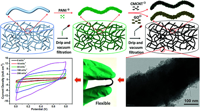
Introduction
The increasing demand for green flexible electronic devices, portable microelectronic products, and wearable devices, as well as environmentally-friendly new energy products, has triggered in-depth studies on low-cost flexible electrode materials with high capacity, high speed, long life, high stability, and good biodegradability/biocompatibility.1–5 Supercapacitors are the most promising solution to the abovementioned requirements and hence have become a hot topic of research.6–10 A possible strategy to achieve high specific capacitance, high operating potential, and long-term cycle stability of supercapacitors involves hybridizing a double layer capacitance (EDLC) carbon material with a pseudocapacitance conductive polymer material; this method allows for efficient charge transfer and accelerates the reaction kinetics.11–15
Layer-by-layer (LbL) assembly has been demonstrated to be an effective method to produce carbon material/conductive polymer nanocomposite electrode materials.16–19 The strong affinity between the constituent materials affords a polymer–inorganic hybrid with a hierarchical nanostructure. However, since the conventional and mature LbL assembly method uses a glass (ITO-coated glass) or polymer film (PET, PDMS, PLA, and nanocellulose film) as a carrier, it suffers from insufficient mass loading of the active material.20,21 This is because the active material adheres only to the surface of the glass or film and does not penetrate deeper into the glass or film to form more deposition. Hence, it is unsuitable for application to the large-scale, controlled fabrication of flexible supercapacitor electrodes with high energy and power densities. One of the novel concepts in this regard is the use of biomass-based aerogels as carriers for the LbL assembly.22,23 The porous structure of the aerogel with porosity of ∼99% and pore diameter of ∼50 nm can allow the active material to enter its interior for deposition.24,25 However, the reported aerogels are mostly nanosheet structures, rather than nanofibrillar structures. This results in a lower specific surface area and does not maximize the electrochemical performance of the active material attached thereto. If the aerogels have three-dimensional (3D) fibrous network structure, the rugged interconnected fibrous network and large specific surface area of the aerogels would lead to excellent electrochemical performance of the template electrode and greatly improve the flexibility of the electrode.
In this paper, we report the fabrication of a polymer–inorganic hybrid nanocomposite electrode by the hierarchical assembly of polyaniline (PANi)/carboxylic multiwalled carbon nanotubes (CMWCNTs) and PANi/graphene oxide (GO) multilayers on cellulose nanofibril (CNF) aerogels with a nanoscale fiber-entangled network. PANi, CMWCNT, and GO carrying opposite charges were allowed to penetrate the CNF aerogels by vacuum filtration and coated onto the nanofibers in an LbL fashion. CNF is a promising biomass nanomaterial with has an abundance of hydroxyl groups, and it shows excellent structural stability, high mechanical strength and low thermal expansion. Hence, CNF has been used in many applications such as biosensors and energy storage devices.26,27 PANi, CMWCNT, and GO and their composites are among the hottest energy storage materials currently researched. The 3D fibrous networks of the CNF aerogels not only provide a good LbL assembly platform for the PANi/CMWCNT (abbreviated as PC) or PANi/GO (abbreviated as PG) composite electrode, but also increase the specific surface area of the electrode and promote the transport and permeation of the electrolyte ions into the electrode. The resulting flexible composite electrodes exhibit homogeneous distribution of multicomponent micro/nanoarchitectures, with a high areal capacitance of 1.59 F cm−2 and high areal specific energy of 147.23 mW h cm−2 in a two-electrode test.
Experimental procedure
Materials
CNF was prepared from wood bleached kraft pulps with promoted Isogai method.28 GO suspensions (2 mg mL−1, flake diameters: 0.5–2 μm) and CMWCNT (OD < 10 nm, length: 0.5–3 μm, –COOH content: 3.88 wt%) were purchased from XFNANO. PANi (emeraldine base, average Mw: 50 000) was purchased from Sigma Aldrich. 1,2,3,4-Butanetetracarboxylic acid (BTCA) and sodium hypophosphite (SHP) were purchased from Aladdin. tert-Butanol, hydrazine hydrate, dimethylacetamide (DMAc) and hydrochloric acid were purchased from the Sinopharm Chemical Reagents Company.
Preparation of the CNF aerogels
0.3 wt% CNF dispersions were dispersed with tert-butanol/water mixed solution in a 2 : 3 (w/w) ratio using an ultrasonic processor (VCX 1500HV, Sonics & Materials Inc.) at 500 W for 30 min. The amount of BTCA added is 1/2 of the dry weight of CNF. The amount of SHP added is 1/2 of BTCA. The addition of BTCA/SHP (2 : 1 w/w) plays a role in micro-cross-linking. The aqueous dispersions were subsequently frozen in cylindrical plastic moulds at −30 °C for 12 h, followed by lyophilisation in a freeze dryer (LGJ-10D, Beijing Four-Ring Science Instrument Plant Co., Ltd). The resulting freeze-dried aerogels were heated at 175 °C for 5 min to ensure sufficient covalent cross-linking.
Preparation of PANi, CMWCNT, and GO suspensions
Briefly, 1 g PANi (emeraldine base) was added into 50 mL DMAc, and the mixture was stirred for about 10 h using a magnetic stirrer. 5 mL of the above mixture was taken out and added to 45 mL of a pH 3 HCl solution. Then, it was ultrasonically dispersed for 1 hour at 500 W in an ice-water bath. The resulting PANi (emeraldine salt) dispersion was diluted to 0.5 mg mL−1 with ultrapure water, and then the pH of the solution was adjusted to 2.5 with 1 M HCl. CMWCNT powder (0.1 g) was dispersed in ultrapure water (200 mL) and ultrasonically dispersed for 1 hour at 500 W in an ice-water bath to obtain a 0.5 mg mL−1 CMWCNT suspension. Using ultrapure water to dilute GO suspension to 0.5 mg mL−1 and ultrasonically dispersed for 1 hour at 500 W.
LbL assembly of the aerogel electrodes
The nano active materials with opposite charges were assembled inside the aerogels by vacuum filtration. The PANi, CMWCNT, and GO suspensions can be penetrated into the CNF aerogel through a controlled low negative pressure vacuum filtration method. First, the PANi suspension is fully dripped onto the surface of CNF aerogel to make it fully swell and maintain for 15 minutes. Then the vacuum filtration is carried out to remove the PANi. Then, in the same way, the suspension of CMWCNT or GO is dripped onto the surface of CNF aerogel, and 15 min remains after it is fully expanded. This process was repeated to allow the LbL assembly. The assembled aerogels were dialysed by placing them in large amounts of ultrapure water in order to remove residual hydrochloric acid and DMAc, and then freeze-dried after freezing in liquid nitrogen to obtain the desired aerogel electrodes. The resulting aerogel electrodes are referred to as CNF-[PANi/CMWCNT]n (abbreviated as CPCn) or CNF-[PANi/GO]n (abbreviated as CPGn), where the subscripts n refers to the number of assemblies. In order to obtain better electrochemical performance, the CNF-[PANi/GO]n aerogel was reduced using hydrazine hydrate and ammonia in an autoclave at 90 °C for 2 h to form a CNF-[PANi/RGO]n (abbreviated as CPRn) aerogel.
Characterisation and electrical measurements
The sizes and zeta potentials of PANi, CMWCNT, and GO were tested by a Zetasizer Nano ZS instrument (Malvern Instruments Ltd., UK). Fourier transform infrared (FTIR) spectra were measured on a Nicolet iS10 spectrometer (Thermo Fisher Scientific Inc., USA). Raman spectroscopy was recorded using an inVia confocal Raman microscope with diode-laser excitation at 632.8 nm at room temperature (Renishaw, UK). X-ray diffraction (XRD) experiments were conducted using a D8 Advance diffractometer (Bruker Co., Germany) with Cu Kα radiation (λ = 0.154 nm, 40 kV, 40 mA) in the 5–60° 2θ range. X-ray photoelectron spectroscopy (XPS) was recorded on an ESCALAB 250Xi instrument with an Al Kα (hν = 1486.6 eV) X-ray source set at 20 mA (Thermo Fisher Scientific Inc., USA). Scanning electron microscopy (SEM) was performed using an S-4800 field-emission-gun SEM instrument (Hitachi, Japan) at 5.0 kV. Transmission electron microscopy (TEM, Tecnai G2 F30, FEI, USA) was used to characterise the microstructures of the aerogels. Specific surface areas (Brunauer–Emmett–Teller, BET) and pore structure (Barret–Joyner–Halenda, BJH) were calculated using N2-gas-adsorption isotherms (NOVA 1200e Quantachrome, USA). Conductivities were measured using an ST 2253 4-point probe resistivity measurement system (Suzhou Jingge Electronic Co., Ltd, China). Tensile strength were measured on an Instron 5848 instrument (Instron Co., USA).
Electrochemical measurements were conducted using a CHI 660E electrochemical workstation (Shanghai Chenhua Instrument Co., LTD, China) at 25 °C. Each aerogel electrode was compressed at 1 MPa into a film electrode for the subsequent electrochemical test (Fig. S2b and c†). A three-electrode system was employed in 1 M aqueous H2SO4 electrolyte, in which a saturated calomel electrode (SCE) and a Pt electrode were used as the reference and counter electrode, respectively. In the three-electrode test, the electrode was only connected with aluminum sheet and the electrode itself acted as a current collector. The electrochemical experiments of the symmetrical flexible all-solid-state supercapacitor were performed using the PVA/H3PO4 electrolyte by a two-electrode system. A PVA/H3PO4 electrolyte was prepared by mixing PAV (6 g), H3PO4 (6 g) and deionized water (60 mL), and heating to 80 °C until the solution was clarified. The symmetrical all-solid-state supercapacitor device was prepared by the following methods. One side of the prepared electrode was coated with conductive silver paste and connected to aluminum sheet, which was used as the current collector (Fig. S9†). Next the electrode was then immersed in the PVA/H3PO4 electrolyte at least 30 minutes, after which time it was removed from the electrolyte and allowed to dry at 25 °C and under ventilation for 3 hours. Finally, two such electrodes were gently pressed together to obtain a sandwich structure as the all-solid-state supercapacitor device.
Cyclic voltammetry (CV) and galvanostatic charge–discharge (GCD) scanning tests were carried out in the range of 0 to 0.8 V. Electrochemical impedance spectroscopy (EIS) was measured in a frequency range from 0.001 Hz to 100 kHz, at an amplitude of 0.005 V relative to the open circuit potential. For the three-electrode tests, the areal specific capacitance Cs (F cm−2) and the gravimetric specific capacitance Cg (F g−1) were calculated as follows:  and Cg = (IΔt)/(mU), where I (A), v (V s−1), S (cm2), U (V), Δt (s), and m (g), are the current, voltage scan rate, working area of the electrode, voltage window, discharge time, and total electrode weight, respectively. For the two-electrode tests,
  or Cs′′ = 4(IΔt)/(SU), and Cg′ = 4(IΔt)/(mU), where Cs′, Cs′′, and Cg′ are the areal specific capacitances and gravimetric specific capacitance of the supercapacitor devices, respectively.29 The areal energy E (mW h cm−2) and the areal power P (mW cm−2) of the supercapacitor were obtained from the expressions: E = 1/4(U2Cs′′/2) and P = E/Δt, respectively.
Results and discussion
The nano-active materials must be pretreated appropriately to facilitate LbL assembly. The TEM images (Fig. S1†) show that PANi, CMWCNT, and GO have nanoparticle, tubular fiber, and typical nanosheet microstructures, respectively, all suitable for assembly. The average particle sizes of PANi, CMWCNT, and GO were 325, 210, and 315 nm, respectively, and the corresponding zeta potentials were 43.6 (pH ∼ 2.5), −44.3 (pH ∼ 6.9), and −41.2 mV (pH ∼ 6.8), as measured by a laser particle size analyzer. These results indicated that the prepared nano-active material has the appropriate nano-particle size and sufficient surface charge for the subsequent LbL assembly experiments.
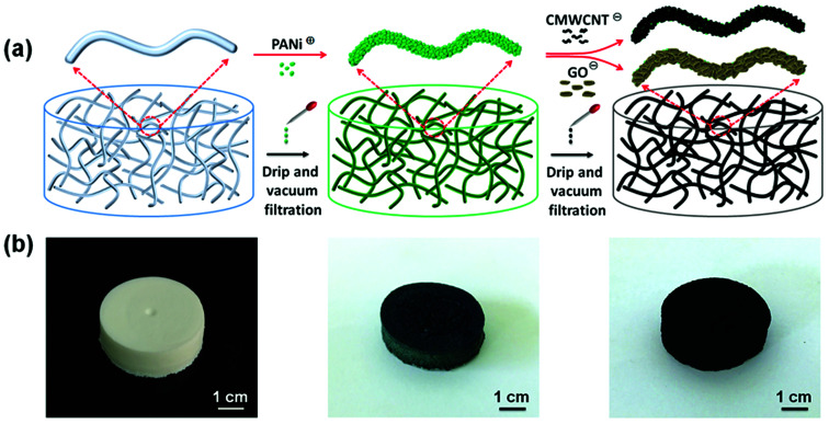
The most typical LbL assembly method involves alternating depositions of two or more components having different surface charges on the supporting substrate by using electrostatic adsorption and hydrogen bonding. In this study, CNF aerogels were used as nanofibrous scaffolds to deposit electrochemically active PANi nanoparticles, CMWCNT nanotubes, and GO nanosheets (Fig. 1a). Briefly, the PANi and CMWCNT (or GO) suspensions were alternately dripped onto the CNF aerogel, and it was ensured that the CNF aerogel had enough time for adsorption and deposition the nanomaterials after each liquid saturation. Then vacuum filtration was used to remove excess liquid. After being assembled only by PANi, the white CNF aerogel turns dark green in color, and finally turns black after being assembled many times through CMWCNT or GO (Fig. 1b). Under the driving force of electrostatic adsorption and hydrogen bonding, conductive polymer PANi with positive charge and inorganic electrochemically active materials GO and carboxylic CMWCNT with negative charge were alternately deposited on the CNF substrate with negative charge to obtain structurally ordered polymer–inorganic hybrid nanocomposite.
Fig. 1. (a) Schematic of the LbL assembly process to fabricate hierarchical PANi/CMWCNT and PANi/GO multilayers on the CNF nanofibrous network. (b) Representative photographs of the CNF aerogel, CNF aerogel following PANi assembly, and CPC10 aerogel from left to right. The appearance of CPG10 aerogel is similar to that of CPC10 aerogel.
An aerogel made of CNF will undergo irreversible structural collapse after it encounters water because CNF is hydrophilic. Increasing the CNF concentration during the preparation of aerogels can increase the mechanical strength and density of aerogels to some extent. However, it can also convert the nanofibrous structure of the aerogels prepared with low concentrations of CNF into nanosheet structures, which reduces the specific surface area and permeability of the aerogel, and makes it unsuitable for the assembled matrix of the nano-active material. To solve this problem, we added tert-butanol to regulate the growth conditions of ice crystals and to inhibit the association between CNF, which changes the microstructure of aerogels.30 BTCA was also added to obtain moderately cross-linked CNF aerogels with sufficient strength and negative charge. The thus-obtained CNF aerogel not only has a nanofiber-like microstructure, but also remains structurally intact after undergoing negative-pressure vacuum filtration several dozen times (Fig. S2a†).
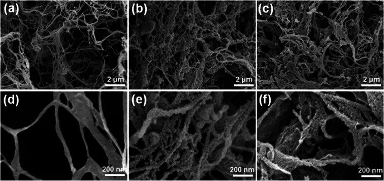
The microstructures of the CNF aerogel before and after assembly were analyzed by SEM. The SEM images (Fig. 2) show that even after BTCA micro-crosslinking, the CNF aerogel retains a fibrillar porous network structure (Fig. 2a), as described above, due to the influence of tert-butanol on ice crystal growth and CNF association. At high magnification, the surface of the CNF appears relatively smooth and the nanofibrils are intertwined with each other, with diameters of 50–200 nm (Fig. 2d). After the assembly of PANi and CMWCNT, the aerogel maintains a fibrillar network structure (Fig. 2b). Under high magnification, the surface of the nanofibrils exhibit a granular rough structure (Fig. 2e), indicating that PANi and CMWCNT are uniformly deposited on the CNF, and there is no obvious agglomeration. Similarly, after the assembly of PANi and GO, the aerogel maintains a fibrillar network structure (Fig. 2c), and the nanofibril surface also has a granular rough structure (Fig. 2f). Slightly different from the CPC10 aerogel, the fibrillar nature of the CPG10 aerogel decreased a little, and more nanofilm structure appeared. This may be due to the larger diameter of the GO used herein, resulting in nanofibrils having small diameter, to be encapsulated by the GO layer, forming a nanofilm structure.
Fig. 2. SEM images of nanofibrous networks microstructures of different aerogels: (a and d) CNF aerogel, (b and e) CPC10 aerogel, and (c and f) CPG10 aerogel at different magnifications.
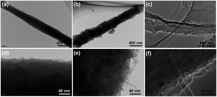
We also use TEM to analyze the microstructures of CNF aerogel before and after its assembly (Fig. 3). Before assembly, the surface of nanofibrils formed by CNF association is very smooth (Fig. 3a and S3a†). After assembly, PANi and CMWCNTs adhered to the nanofibril surface to form a rough bundle-like structure (Fig. 3b and S3b†), while PANi and GO formed a rough wrinkled structure (Fig. 3c and S3c†). Local amplification reveals that after PANi assembly alone, PANi was uniformly deposited on the nanofibril surface to form a distinct nanoparticle structure (Fig. 3d). After 10 rounds of assembly, PANi and CMWCNT were interspersed with each other on the nanofibril surface, and the nanotube structure of the CMWCNT was clearly visible on the outermost layer (Fig. 3e). PANi and GO were stacked one after another on the nanofibril surface, and in the outermost layer, the wrinkled lamellar structure formed by GO was clearly seen (Fig. 3f). The SEM and TEM analyses revealed that the nano-active material was successfully assembled on the nanofibrils inside the CNF aerogel.
Fig. 3. TEM images of (a) pure CNF nanofibrils, (b) PC10, and (c) PG10 assembled on CNF nanofibril. (d) Locally enlarged TEM image of only PANi assembled on CNF nanofibril. Locally enlarged TEM image of (e) PC10 and (f) PG10 assembled on CNF nanofibrils.
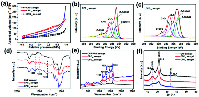
Generally, the higher the specific surface area of the electrode material, the larger is the contact area between the electrode and the electrolyte, leading to better electrochemical performance.31 The specific surface area and pore structure of CNF aerogels before and after assembly were analyzed by the nitrogen adsorption method (Fig. 4a and S4a†). The BET specific surface area of CNF aerogel before assembly can reach 63 ± 1 m2 g−1 and the pore volume can reach 0.137 cm3 g−1. After assembly, the specific surface areas of the CPC10 and CPG10 aerogels improved to 183 ± 1 and 86 ± 1 m2 g−1, respectively, and their corresponding pore volumes improved to 0.245 and 0.471 cm3 g−1. The CPC10 aerogel has higher specific surface area than the CPG10 aerogel, but the pore volume is slightly smaller, indicating that the CPC10 aerogel has more micropores, while the CPG10 aerogel has more mesopores and macropores. This is consistent with the results of the microstructure analyses.
Fig. 4. (a) Nitrogen adsorption/desorption isotherms for the CNF, CPC10, and CPG10 aerogels. High-resolution XPS C1s spectra of (b) CPC10 and (c) CPG10 aerogels. (d) FTIR spectra and (f) XRD pattern of the CNF, CPC10, and CPG10 aerogels. (e) Raman spectra of the CNF/PANi, CPC10, and CPG10 aerogels. CNF/PANi aerogels means that only PANi is assembled on CNF nanofibril.
The physicochemical structures of CNF aerogel before and after its assembly were studied by XPS, FTIR, Raman spectroscopy, and XRD. The composition and proportion of surface elements of the three aerogels changed significantly after assembly (Fig. S4b†). The C/O ratios of the CNF, CPC10, and CPG10 aerogels are 1.01, 3.18 and 1.89, respectively (Fig. S4c†). This change is also directly reflected by the C1s spectra of the three aerogels. Compared with the C–O peak intensity of the CNF aerogel at 286.2 eV, the C–O peaks at 286.1 and 286.8 eV for the CPC10 and CPG10 aerogels, respectively, decreased significantly in intensity. This decrease is in relation to the C C/C–C peak intensity at the correction position of 284.8 eV. Compared with the C1s peaks of the CNF aerogel, extra peaks at 285.1 and 285.4 eV are observed for CPC10 (Fig. 4b) and CPG10 (Fig. 4c) aerogels, respectively, which should be ascribed to the C–N/C N peak.32 Because there are many carboxyl (–COOH) groups on CMWCNT and GO, which can form N–O–C linkage through the amino functional groups of PANi.33 We also show the N1s XPS spectra of PANi, in which the peaks at 399.6 and 400.2 eV are assigned to –NH– and –NH+– groups, while the one at 401.7 eV is ascribed to the NH+– groups (Fig. S4e and f†). The FTIR spectra of CNF aerogel before and after its assembly (Fig. 4d) show the changes in functional groups. After assembly, new peaks appeared for both CPC10 and CPG10 aerogels, corresponding to the N Q N stretching vibrations at 1587 cm−1, N–B–N stretching vibrations at 1501 cm−1 (where B and Q represent the benzenoid and quinoid moieties), and C–N stretching vibrations at 1313 cm−1, with aromatic conjugation that are characteristic of PANi.34 Raman spectroscopy was also used to obtain structural information about the nano-active materials assembled inside the CNF aerogel. The Raman spectra of both CPC10 and CPG10 aerogels after assembly show five peaks: the peaks at 1161 and 1218 cm−1 are ascribed to the C–H bending of the Q and B ring vibrations, the peaks at 1465 cm−1 are attributed to the C N bending, while those at 1328 and 1591 cm−1 are assigned to the D and G singles of the of graphitic fragments of CMWCNTs and GO, respectively (Fig. 4e).32,33Fig. 4f shows the XRD patterns of the three aerogels. The diffraction peaks at 2θ = 14.8° (101), 21.6° (002), and 33.7° (040), correspond to the cellulose I crystalline structure and completely masked the peaks of the nano-active materials. Therefore, BET surface area, and the XPS, FTIR, XRD, and Raman spectra confirmed successful LbL assembly of nano-active materials into CNF aerogels.
To verify that the supercapacitor electrodes prepared by assembling nano-active materials with CNF aerogels as the skeleton have better electrochemical performance than the electrodes assembled by the traditional film, the electrochemical properties of the as-prepared CPC10 and CPR10 supercapacitor electrodes were first examined by a standard three-electrode system in 1 M H2SO4 aqueous solution. Then, a two-electrode system was used to further analyze the symmetric supercapacitor devices prepared by CPC10 and CPR10 with PVA/H3PO4 gel as the electrolyte. The influence of LbL assembly cycles on the electrochemical performance of the supercapacitor electrodes was also analyzed.
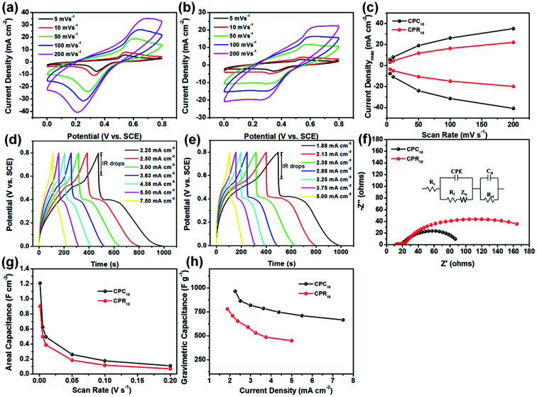
Fig. 5a and b show the typical CV curves of the CPC10 and CPR10 electrodes, respectively, at scan rates varying from 2 to 200 mV s−1. Both show obvious redox peaks, which mainly correspond to the leucoemeraldine/emeraldine and emeraldine/pernigraniline redox reactions of PANi.32 At the same scan rate, the redox peaks of CPC10 are stronger than those of CPR10 (Fig. S5a†) because CPC10 has a microporous structure and higher specific surface area than CPR10, which is beneficial for ion diffusion.35 An increase in the scan rate causes the anodic and cathodic peaks to shift to higher and lower potentials, respectively, due to the internal resistance of the electrode. The relationship between maximum current density and scan rate for the two electrodes is displayed in Fig. 5c. Notably, maximum current densities for both electrodes increased nonlinearly with scan rate. According to the power law equation I avb, where I and v are current density and scan rate, respectively, and adjustable parameters a and b can be obtained from the intercept and slope of a linear plot of log I vs. log v, respectively.32,36 When the b value is 0.5, it is an ideal diffusion-controlled process. When the b value is 1, it is an ideal non-diffusion controlled process. When the b value is between the two, it is a complex control process. The b values of the CPC10 and CPR10 electrodes reach 0.51 and 0.54 in anodic scans (Fig. S5b†), implying that both electrodes operate their redox processes through a complex control mechanisms, respectively.32,36 The GCD curves of the two electrodes also show obvious pseudopotential capacitance (Fig. 5d and e). At the same current density, CPC10 has longer charge and discharge times than CPR10. The IR drops of CPC10 and CPR10 electrodes at different current densities in a three-electrode test were ∼0.20 V and ∼0.24 V, respectively (Fig. 5d and e). The Nyquist plots of the CPC10 and CPR10 electrodes, obtained using EIS at the open circuit potential are shown in Fig. 5f. The equivalent series resistance (ESR) of the two electrodes is nearly the same (13.67 Ω for CPC10 and 12.12 Ω for CPR10), but the charge transfer resistance (Rct) of CPC10 (62.82 Ω) is much smaller than that of CPR10 (140.85 Ω), indicating that CPC10 has better ion accessibility in the electrolyte. Bode plots of the CPC10 and CPR10 electrodes also show that the impedance Z is relatively small at high frequencies; as the frequency decreases, Z sharply increases and becomes less frequency dependent (Fig. S7a†). The phase angles of the two electrodes increase rapidly with the increase of the frequency to the maximum values of 26° (CPC10) and 31° (CPR10), and then drop rapidly and eventually drop to about 2 (Fig. S7b†).
Fig. 5. CV curves of the (a) CPC10 and (b) CPR10 electrodes at different scan rates. (c) Maximum current vs. scan rate of two electrodes determined from their corresponding CV curves. GCD curves for the (d) CPC10 and (e) CPR10 electrodes at different current densities. (f) Nyquist plots of the two electrodes. (g) Areal capacitances of the two electrodes at different scan rates. (h) Gravimetric capacitances of the two electrodes at different current densities. All data were obtained under three-electrode testing conditions in 1 M H2SO4.
Good accessible capability of ions in the electrolyte renders higher capacitance performance to CPC10 (Fig. 5g) in terms of the areal specific capacitance calculated from the CV curves at different scan rates and the gravimetric specific capacitance calculated from the GCD curves at different current densities (Fig. 5h). The CPC10 showed a very high areal specific capacitance of 1.21 F cm−2 at a scan rate of 1 mV s−1, whereas CPR10 had an areal specific capacitance of only 0.90 F cm−2 under the same conditions. The CPC10 also has a larger gravimetric specific capacitance (965.80 F g−1 at a current density of 2.25 mA cm−2) than that of CPR10 (780.64 F g−1 at a current density of 1.875 mA cm−2). Moreover, these capacitance properties achieved by the LbL assembly the nanocomposite active materials within the CNF aerogels were better than those of previously reported PANi/RGO assemblies,37 PANi/RGO LbL films,38 and PANi/RGO LbL hollow spheres39 under the same test conditions. These capacitance properties further confirm that PANi, CMWCNT, and RGO, LbL assembled on the nanofibrils inside the porous CNF aerogel, can achieve outstanding electrochemical performance.
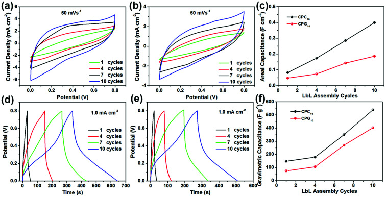
To verify the performance of the LbL-assembled electrode in practical applications, an all-solid symmetric supercapacitor was prepared using CPCn and CPRn as electrode materials with PVA/H3PO4 gel as the electrolyte. We first investigated the effect of the number of LbL assembly cycles on the electrochemical performance of the supercapacitor electrode (Fig. 6). Fig. 6a and b show the CV curves of the two supercapacitors obtained at a scan rate of 50 mV s−1 for different LbL assembly cycles. With increasing number of LbL assembly cycles, the CV curve becomes more regular, and the integral area of the curve and the areal specific capacitance calculated from the CV curve increase gradually. For the same LbL assembly cycle, the areal specific capacitance of CPCn is greater than that of CPRn, and presents an approximately linear relationship with the number of LbL assembly cycles (Fig. 6c). Similar phenomena also appear on the GCD curve (Fig. 6d and e). At a current density of 1.0 mA cm−2, with increasing number of LbL assembly cycles, the GCD curve approaches a symmetric triangle, and the charge–discharge time and gravimetric specific capacitance obtained according to the GCD curve increase (Fig. 6f). This is because the mass loading of the nano-active material on the CNF aerogel increases gradually with increasing number of LbL assembly cycles (Fig. S6a†), resulting in an increase in the degree of denser packing of the nano-active material, forming more continuous conductive networks inside the electrode (Fig. S6b†), thus providing more interrelated pathways for electron transport, and improving electrochemical performance.
Fig. 6. CV curves of the (a) CPCn and (b) CPRn electrodes at different LbL assembly cycles. (c) Areal specific capacitance of the two electrodes at different LbL assembly cycles. GCD curves of (d) CPCn and (e) CPRn electrodes at different LbL assembly cycles. (f) Gravimetric specific capacitance of the two electrodes at different LbL assembly cycles. All data were obtained under two-electrode testing conditions with PVA/H3PO4 gel electrolyte.
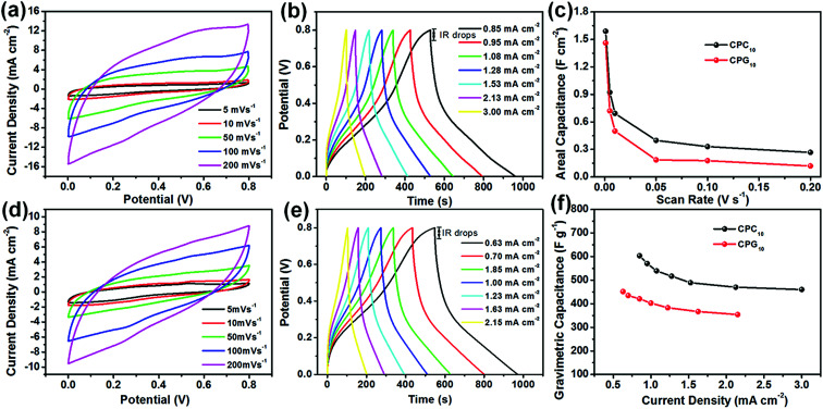
The detailed information of the as-prepared all-solid symmetric supercapacitors with electrodes prepared by 10 LbL assembly cycles is investigated by CV, GCD, and EIS in Fig. 7. The CV curves of the CPC10 and CPR10 supercapacitors obtained at different scan rates (Fig. 7a and d, respectively) show almost rectangular shapes and can be maintained without any obvious distortion at 200 mV s−1, especially for CPC10, illustrating good charge transfer performance inside the supercapacitor. The GCD curves of both CPC10 and CPR10 supercapacitors at different current densities (Fig. 7b and e) show approximately symmetric triangles, indicating good charge and discharge performance for both supercapacitors; the GCD curve is especially regular for CPC10. The IR drops of CPC10 and CPR10 supercapacitors at different current densities in a two-electrode test were ∼0.05 V and ∼0.06 V, respectively. The IR drops of the symmetric devices were smaller than that of electrode samples. This was because in the three-electrode test, the electrode samples were swelling slowly due to hydrophilic properties of nanocellulose during testing, resulting in an increase in the distance between the conductive networks inside the electrodes and a decrease of interrelated pathways for electron transport, which decreased the electrical conductivities and then increased IR drops.22,40 The electrodes of symmetric devices almost maintained the same volume in PVA/H3PO4 gel electrolyte during testing. Thus the electrodes of symmetric devices showed smaller IR drops. From the Nyquist plot (Fig. S7c†), CPC10 and CPR10 have ESR values of 15.80 Ω and 23.05 Ω, respectively, indicating that CPC10 has a smaller internal resistance than CPR10. The Rct of the CPC10 (2.01 Ω) is also lower than that of the CPR10 (2.29 Ω). Bode plots of the symmetric devices also show that the impedance Z sharply decreases as the frequency increases and then levels off gradually (Fig S7d†). The Bode plot between phase angles versus frequency (Fig. S7e†) shows a similar trend. The phase angles approach to 70° (CPC10) and 63° (CPR10) at low frequencies; as the frequency increases, both phase angles sharply decrease and approach zero (Fig. S7e†). The CPC10 supercapacitor shows relatively better electrochemical performance than the CPR10 supercapacitor because the CPC10 aerogel has better fibrillar network structure and higher specific surface area, facilitating ion diffusion and electron transport, consistent with the above analysis results.
Fig. 7. CV curves of the (a) CPC10 and (d) CPR10 electrodes at different scan rates. (c) Areal capacitances of the two electrodes at different scan rates. GCD curves for the (b) CPC10 and (e) CPR10 electrodes at different current densities. (f) Gravimetric capacitances of the two electrodes at different current densities. All data were obtained under two-electrode testing conditions with PVA/H3PO4 gel electrolyte.
For comparison, from the CV curves at 1 mV s−1, the areal specific capacitances were calculated to be 1.59 and 1.46 F cm−2 for the CPC10 and CPR10 electrodes, respectively (Fig. 7c). The areal specific capacitance of the LbL assembled supercapacitor electrode is higher than those of other electrodes prepared by other methods using similar electroactive materials, such as PANi/RGO assembled CNF-based film electrode,41 carbon nanotube/PANi hydrogel film electrodes,42 and 3D porous RGO/PANi composites.43 Moreover, the highest gravimetric specific capacitance values were 603.39 F g−1 at a current density of 0.85 mA cm−2 and 451.57 F g−1 at a current density of 0.63 mA cm−2 for CPC10 and CPR10 electrodes, respectively. Both supercapacitor electrodes exhibited slight declines in rate performance, with 76.29% capacitance retention for CPC10 when the current density was increased from 0.85 to 3.0 mA cm−2, and 78.42% capacitance retention for CPR10 when the current density was increased from 0.63 to 2.15 mA cm−2.
The superior energy storage performance and outstanding rate capabilities of the LbL-assembled nanocomposite electrodes can be attributed to the unique multilayer configuration and hybrid nanoarchitectures. The LbL-assembled hybrid structures created by PANi/CMWCNT and PANi/RGO on the surface of CNF nanofibrils creates an interconnected network, which shortens the ion migration and diffusion paths, thus promoting rapid ion intercalation/de-intercalation during the rapid redox process. Furthermore, the high-specific-area 3D fibrous networks of the CNF aerogels not only acts as the scaffold for nano-active material, but also facilitates permeability of the aqueous electrolyte into the electrode because of the natural hydrophilic properties of CNF.26
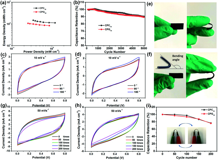
To further study the electrochemical performance of the supercapacitors in practical applications, the power density and energy density of the prepared all-solid supercapacitors were calculated from the GCD curve. The two types of supercapacitors exhibit a clear correspondence between power output and energy density (Fig. 8a). The CPC10 supercapacitor exhibits a maximum areal specific energy of 147.23 mW h cm−2 at an areal specific power of 0.34 mW cm−2 and retains an areal specific energy of 112.32 mW h cm−2 at a higher areal specific power of 1.20 mW cm−2. The performance of the CPR10 supercapacitor is slightly lower than that of CPC10, and the former shows an areal specific energy of 106.57 mW h cm−2 at an areal specific power of 0.25 mW cm−2. Gravimetric or volumetric energy and power of CPC10 and CPR10 supercapacitor are presented in Fig. S11.† The CPC10 has maximum energy density of 48 429 mW h g−1 (956 mW h cm−3) at a power density of 111 mW g−1 (2.21 mW cm−3), and the CPR10 has maximum energy density of 36 248 mW h g−1 (745 mW h cm−3) at a power density of 85 mW g−1 (1.76 mW cm−3).
Fig. 8. (a) Ragone plots of power density vs. energy density for the two assembled supercapacitors. (b) Cycling stabilities of the two assembled supercapacitors. CV curves of (c) CPC10 and (d) CPR10 electrodes at different bending angles. Representative photographs of (e) CPC10 and (f) CPR10 electrodes in normal and bent states. CV curves of (g) CPC10 and (h) CPR10 electrodes after folding 200 times at a scan rate of 50 mV s−1. (i) Stability of electrode capacitance after 200 bending cycles according to CV curves in (g) and (h). Illustration is the schematic diagram of the electrode's bending state. All data were obtained under two-electrode testing conditions with PVA/H3PO4 gel electrolyte.
Cyclic stability tests of the two supercapacitors were conducted by repeating the CV cycles at a scan rate of 10 mV s−1 (Fig. 8b and S8†). After 5000 CV cycles, the CPC10 and CPR10 supercapacitors retained about 90.47% and 89.33% capacitance, respectively. The two types of supercapacitors also showed coulombic efficiency of ∼85% throughout the various current densities (Fig. S10a†). The excellent electrochemical durability reflected the reversibility of the charge storage reaction of the prepared all-solid supercapacitor with stable adhesion of nano-active material on the CNF aerogels. Both supercapacitor electrodes have good flexibilities due to their nanocellulose skeletons (Fig. 8e and f). To evaluate their potential applications in flexible and wearable electronic devices, the electrochemical performance of the two supercapacitors at different bending angles was characterized. The CV curves at a scan rate of 10 mV s−1 (Fig. 8c and d) showed no significant change in the integrated area of the curve under bending, indicating the excellent flexibility of the device. The electrochemical performance of the two supercapacitors with different bending times was also characterized. As shown in Fig. 8g, h and i, both the CPC10 and CPR10 electrodes still have good flexibilities in bent states and have the capacitance retention of 97.44% and 93.47% after 100 bending times, respectively. Even after 200 bending times, the capacitance retention still have 76.58% and 75.94%, respectively. The stress–strain data also showed that the tensile strengths of CPC10 and CPR10 electrodes were 2.83 and 3.19 MPa, respectively, which were shown in Fig. S10b.† The above results showed that both electrodes had good flexibility properties.
Conclusions
In summary, we propose a simple LbL assembly of PANi/CMWCNT and PANi/RGO composites on CNF aerogels with a fibrillar porous network structure via drip and vacuum filtration, in order to obtain nanocomposite electrodes. The nano-active materials deposited on the nanofibril scaffolds showed uniformly distributed multilayer nanoarchitectures, especially in the case of the CPCn aerogels. The CNF aerogels with a highly porous and accessible nanofibrillar network not only provide a large surface area for the nano-active materials without agglomeration, but also allow for efficient diffusion and permeation of the electrolyte ions. This unique structure imparts CPC10 and CPR10 with high gravimetric specific capacities of 965.80 and 780.64 F g−1, respectively, during three-electrode testing. In addition, high areal specific capacitances of 1.59 and 1.46 F cm−2 and good energy densities of 147.23 and 112.32 mW h cm−2, respectively, are observed during two-electrode testing. The electrodes show excellent rate capability as well as good durability and flexibility without obvious curve abnormity at different bending angles. We believe that this LbL assembly method using an aerogel is a simple and effective means of creating nanostructured electrodes for green and flexible energy storage devices.
Conflicts of interest
There are no conflicts to declare.
Supplementary Material
Acknowledgments
This work was supported by the Special Fund for Forest Scientific Research in the Public Welfare (No. 201504603) and the Fundamental Research Funds of CAF (No. CAFYBB2017ZX003).
Electronic supplementary information (ESI) available. See DOI: 10.1039/c9ra02449b
References
- He J. Wang N. Cui Z. Du H. Fu L. Huang C. Yang Z. Shen X. Yi Y. Tu Z. Nat. Commun. 2017;8:1172. doi: 10.1038/s41467-017-01202-2. [DOI] [PMC free article] [PubMed] [Google Scholar]
- Wang X. W. Guo H. P. Liang J. Zhang J. F. Zhang B. Wang J. Z. Luo W. B. Liu H. K. Dou S. X. Adv. Funct. Mater. 2018;28:1801016. doi: 10.1002/adfm.201801016. [DOI] [Google Scholar]
- Choudhury A. Kim J.-H. Sinha Mahapatra S. Yang K.-S. Yang D.-J. ACS Sustainable Chem. Eng. 2017;5:2109–2118. doi: 10.1021/acssuschemeng.6b02031. [DOI] [Google Scholar]
- Zhao D. Chen C. Zhang Q. Chen W. Liu S. Wang Q. Liu Y. Li J. Yu H. Adv. Energy Mater. 2017;7:1700739. doi: 10.1002/aenm.201700739. [DOI] [Google Scholar]
- Kanaparthi S. Badhulika S. Sens. Actuators, B. 2017;242:857–864. doi: 10.1016/j.snb.2016.09.172. [DOI] [Google Scholar]
- Yu L. Hu L. Anasori B. Liu Y.-T. Zhu Q. Zhang P. Gogotsi Y. Xu B. ACS Energy Lett. 2018;3:1597–1603. doi: 10.1021/acsenergylett.8b00718. [DOI] [Google Scholar]
- Zhu J. Tang S. Wu J. Shi X. Zhu B. Meng X. Adv. Energy Mater. 2017;7:1601234. doi: 10.1002/aenm.201601234. [DOI] [Google Scholar]
- Ramadoss A. Yoon K.-Y. Kwak M.-J. Kim S.-I. Ryu S.-T. Jang J.-H. J. Power Sources. 2017;337:159–165. doi: 10.1016/j.jpowsour.2016.10.091. [DOI] [Google Scholar]
- Qin T. Peng S. Hao J. Wen Y. Wang Z. Wang X. He D. Zhang J. Hou J. Cao G. Adv. Energy Mater. 2017;7:1700409. doi: 10.1002/aenm.201700409. [DOI] [Google Scholar]
- Ko Y. Kwon M. Bae W. K. Lee B. Lee S. W. Cho J. Nat. Commun. 2017;8:536. doi: 10.1038/s41467-017-00550-3. [DOI] [PMC free article] [PubMed] [Google Scholar]
- Tang G. Cao L. Xiao P. Zhang Y. Liu H. J. Power Sources. 2017;355:1–7. doi: 10.1016/j.jpowsour.2017.04.053. [DOI] [Google Scholar]
- Zhang X. Wang J. Liu J. Wu J. Chen H. Bi H. Carbon. 2017;115:134–146. doi: 10.1016/j.carbon.2017.01.005. [DOI] [Google Scholar]
- Shi Y. Peng L. Ding Y. Zhao Y. Yu G. Chem. Soc. Rev. 2015;44:6684–6696. doi: 10.1039/C5CS00362H. [DOI] [PubMed] [Google Scholar]
- Dubal D. P. Ayyad O. Ruiz V. Gomez-Romero P. Chem. Soc. Rev. 2015;44:1777–1790. doi: 10.1039/C4CS00266K. [DOI] [PubMed] [Google Scholar]
- Mousavi M. F. Hashemi M. Rahmanifar M. S. Noori A. Electrochim. Acta. 2017;228:290–298. doi: 10.1016/j.electacta.2017.01.027. [DOI] [Google Scholar]
- Bucur C. B. Jones M. Kopylov M. Spear J. Muldoon J. Energy Environ. Sci. 2017;10:905–911. doi: 10.1039/C7EE00398F. [DOI] [Google Scholar]
- Jana M. Saha S. Samanta P. Murmu N. C. Kim N. H. Kuila T. Lee J. H. J. Power Sources. 2017;340:380–392. doi: 10.1016/j.jpowsour.2016.11.096. [DOI] [Google Scholar]
- Marmisollé W. A. Azzaroni O. Nanoscale. 2016;8:9890–9918. doi: 10.1039/C5NR08326E. [DOI] [PubMed] [Google Scholar]
- Xiao F.-X. Pagliaro M. Xu Y.-J. Liu B. Chem. Soc. Rev. 2016;45:3088–3121. doi: 10.1039/C5CS00781J. [DOI] [PubMed] [Google Scholar]
- Kwon S. R. Elinski M. B. Batteas J. D. Lutkenhaus J. L. ACS Appl. Mater. Interfaces. 2017;9:17125–17135. doi: 10.1021/acsami.7b03449. [DOI] [PubMed] [Google Scholar]
- Zhou Z. Panatdasirisuk W. Mathis T. S. Anasori B. Lu C. Zhang X. Liao Z. Gogotsi Y. Yang S. Nanoscale. 2018;10:6005–6013. doi: 10.1039/C8NR00313K. [DOI] [PubMed] [Google Scholar]
- Nyström G. Marais A. Karabulut E. Wågberg L. Cui Y. Hamedi M. M. Nat. Commun. 2015;6:7259. doi: 10.1038/ncomms8259. [DOI] [PMC free article] [PubMed] [Google Scholar]
- Lyu S. Chen Y. Han S. Guo L. Chen Z. Lu Y. Chen Y. Yang N. Wang S. RSC Adv. 2018;8:13191–13199. doi: 10.1039/C8RA01754A. [DOI] [PMC free article] [PubMed] [Google Scholar]
- Lavoine N. Bergström L. J. Mater. Chem. A. 2017;5:16105–16117. doi: 10.1039/C7TA02807E. [DOI] [Google Scholar]
- De France K. J. Hoare T. Cranston E. D. Chem. Mater. 2017;29:4609–4631. doi: 10.1021/acs.chemmater.7b00531. [DOI] [Google Scholar]
- Chen W. Yu H. Lee S.-Y. Wei T. Li J. Fan Z. Chem. Soc. Rev. 2018;47:2837–2872. doi: 10.1039/C7CS00790F. [DOI] [PubMed] [Google Scholar]
- Jiang F. Li T. Li Y. Zhang Y. Gong A. Dai J. Hitz E. Luo W. Hu L. Adv. Mater. 2018;30:1703453. doi: 10.1002/adma.201703453. [DOI] [PubMed] [Google Scholar]
- Saito T. Isogai A. Biomacromolecules. 2004;5:1983–1989. doi: 10.1021/bm0497769. [DOI] [PubMed] [Google Scholar]
- Shao Y. El-Kady M. F. Lin C. W. Zhu G. Marsh K. L. Hwang J. Y. Zhang Q. Li Y. Wang H. Kaner R. B. Adv. Mater. 2016;28:6719–6726. doi: 10.1002/adma.201506157. [DOI] [PubMed] [Google Scholar]
- Jiang F. Hsieh Y.-L. ACS Appl. Mater. Interfaces. 2014;6:20075–20084. doi: 10.1021/am505626a. [DOI] [PubMed] [Google Scholar]
- Li Y. Fu Z. Y. Su B. L. Adv. Funct. Mater. 2012;22:4634–4667. doi: 10.1002/adfm.201200591. [DOI] [Google Scholar]
- Jeon J.-W. Kwon S. R. Lutkenhaus J. L. J. Mater. Chem. A. 2015;3:3757–3767. doi: 10.1039/C4TA04697H. [DOI] [Google Scholar]
- Hyder M. N. Lee S. W. Cebeci F. Ç. Schmidt D. J. Shao-Horn Y. Hammond P. T. ACS Nano. 2011;5:8552–8561. doi: 10.1021/nn2029617. [DOI] [PubMed] [Google Scholar]
- Zhang L. Huang D. Hu N. Yang C. Li M. Wei H. Yang Z. Su Y. Zhang Y. J. Power Sources. 2017;342:1–8. doi: 10.1016/j.jpowsour.2016.11.068. [DOI] [Google Scholar]
- Kim S. Y. Hong J. Kavian R. Lee S. W. Hyder M. N. Shao-Horn Y. Hammond P. T. Energy Environ. Sci. 2013;6:888–897. doi: 10.1039/C2EE23318E. [DOI] [Google Scholar]
- Shao L. Jeon J.-W. Lutkenhaus J. L. J. Mater. Chem. A. 2013;1:7648–7656. doi: 10.1039/C3TA10961E. [DOI] [Google Scholar]
- Lee T. Yun T. Park B. Sharma B. Song H.-K. Kim B.-S. J. Mater. Chem. 2012;22:21092–21099. doi: 10.1039/C2JM33111J. [DOI] [Google Scholar]
- Sarker A. K. Hong J.-D. Langmuir. 2012;28:12637–12646. doi: 10.1021/la3021589. [DOI] [PubMed] [Google Scholar]
- Luo J. Ma Q. Gu H. Zheng Y. Liu X. Electrochim. Acta. 2015;173:184–192. doi: 10.1016/j.electacta.2015.05.053. [DOI] [Google Scholar]
- Yang X. Shi K. Zhitomirsky I. Cranston E. D. Adv. Mater. 2015;27:6104–6109. doi: 10.1002/adma.201502284. [DOI] [PubMed] [Google Scholar]
- Wang X. Gao K. Shao Z. Peng X. Wu X. Wang F. J. Power Sources. 2014;249:148–155. doi: 10.1016/j.jpowsour.2013.09.130. [DOI] [Google Scholar]
- Zeng S. Chen H. Cai F. Kang Y. Chen M. Li Q. J. Mater. Chem. A. 2015;3:23864–23870. doi: 10.1039/C5TA05937B. [DOI] [Google Scholar]
- Zhou Q. Li Y. Huang L. Li C. Shi G. J. Mater. Chem. A. 2014;2:17489–17494. doi: 10.1039/C4TA03639E. [DOI] [Google Scholar]
Associated Data
This section collects any data citations, data availability statements, or supplementary materials included in this article.


