

Abstract
Topographical cues play an important role in influencing cellular behavior and are considered as significant parameters to be controlled in tissue engineering applications. This work investigated the biocompatibility with regard to scaffold architecture and topographical effect of nanofibrous scaffolds on the in vivo and in vitro foreign body reaction. Random and aligned polycaprolactone (PCL) nanofibers were fabricated by electrospinning technique, with diameters of 313 ± 5 nm and 506 ± 24 nm, respectively. Primary monocytes isolated from five human donors were cultured on PCL nanofibers, PCL film, and RGD-coated glass in vitro and cell density and morphology was evaluated at time points of day 0 (2 h), day 3, day 7, and day 10. The in vivo study was carried out by implanting PCL nanofibers and film scaffolds subcutaneously in rats to test the biocompatibility and host response at time points of week 1, week 2, and week 4. The in vitro studies revealed that the initial monocyte adhesion on the aligned fiber scaffold was significantly less (p < 0.001) when compared to the random fiber scaffold. The in vivo study showed that the thicknesses of fibrous capsule on fibrous scaffolds were 7.55 ± 0.54 µm for aligned fibers and 4.13 ± 0.31 µm for random fibers, which were significantly thinner than that of film implants 37.7 ± 0.25 µm (p < 0.001). Additionally, cell infiltration was observed in aligned fibrous scaffolds both in vitro and in vivo, while on random fibers and films, distinct fibrous capsule boundaries were found on the surfaces. These results indicate that aligned electrospun nanofibers may serve as a promising scaffold for tissue engineering by minimizing host response, enhancing tissue-scaffold integration, and eliciting a thinner fibrous capsule.
Keywords: foreign body reaction, electrospinning, nanofiber, nanotopography, cell infiltration, fibrous capsule
Introduction:
The foreign body reaction is a normal component of the healing process which is observed after implantation of medical devices in the host. It is the end-stage of the inflammatory and wound healing response. Macrophage and foreign body giant cells play a crucial role in the foreign body reaction, and their responses toward implanted materials have significant impact on the proper functioning of medical devices.1 Inappropriate tissue response on the material surface often leads to device failure. The formation of the fibrous capsule during the foreign body reaction is one common barrier for normal function of medical devices, such as biosensors,2,3 drug delivery systems,4,5 eye implants,6 etc. Efforts have been made to reduce fibrous capsule thickness. Unfortunately, due to limited knowledge of the mechanism of the foreign body response to implanted materials, fulfilling complete function of medical devices remains challenging. Material surface chemistry,7 physical properties,8 and morphological features9 all play a part in modulating cellular reactions towards implant materials.
Biomaterial topography may have a significant impact on the foreign body reaction.10 Porous structures tend to result in a moderate tissue response and enable faster healing processes, with fibrous capsule formation on a porous surface often found to be thinner than that on a dense solid implant sur-face.11,12 Surface geometry has also been extensively studied to understand its influence on macrophage behavior and host responses. Micropatterned grooves and ridges have been used as substrates to understand macrophage behaviors and foreign body reactions towards micro-sized topography.9,13,14 The study of nanotopography is also substantial because the natural extracellular matrix (ECM) surrounding cells often comprises of nano-sized components.15 A number of studies investigated macrophage responses or tissue reactions toward nano-sized surface geometry.16–19 However, these studies are far from exhaustive in understanding the underlying mechanism. In the present study, we provide additional understanding of the nanotopographical influence of electrospun nanofiber scaffolds on the foreign body reaction both in vitro and in vivo. We used a biocompatible syn-thetic polymer, polycaprolactone (PCL), to fabricate aligned and random nanofiber scaffolds by electro-spinning as well as a PCL film used as a control to investigate the nanofiber topographic effect on the in vivo and in vitro foreign body reactions.
Materials and Methods
Preparation of PCL scaffolds
Polycaprolactone (PCL) (Mw: 65,000, Aldrich, USA) nanofibers were fabricated by the electrospinning technique.20 To obtain aligned and random nanofibers with similar fiber diameters, different solvent mixtures and electrospinning parameters were used as indicated in Table 1. For random fibers, PCL was dissolved in a solvent mixture of 2,2,2-trifluoroethanol (TFE) (≥99.0, Fluka, China) and deionized H2O (DI H2O), whereas a mixture of dichloro-methane (DCM) (HPLC grade, VWR, EC) and methanol (HPLC grade, Panceac, EU) was used for aligned fiber fabrication. The polymer solution was loaded into a 3 mL syringe connected to a 22G needle and the solution flow rate was controlled by a syringe pump (New Era pump systems Inc., USA). High DC voltage (GAMMA high voltage research, USA) was applied to the polymer solution and the electrospun fibers were collected using a grounded rotating drum. Because of the weak mechanical properties of aligned fiber scaffolds along the perpendicular direction to the fiber axis, the fibers were deposited directly onto a grounded PCL film to allow easy handling of aligned fibers for further studies. The spinning process was carried out at 20–23°C and the humidity was 51–56%. The PCL film was prepared using a hot press at 65–68°C and a com-pressive force of 12–16 N force (Carver press, model No.: 4128, USA).
Table 1.
Electrospinning Parameters for Aligned and Random PCL Fibers
| Aligned | Random | |
|---|---|---|
| Concentration (wt %) | 9.5 | 14 |
| Solvent Mixture | 3:2 DCM:Methanol | 5:1 TFE:DI H2O |
| Flow rate (mL/h) | 1.5 | 1.5 |
| Distance (cm)a | 8–9 | 13–14 |
| Voltage (kV) | 13–15 | 16–18 |
| Rotator speed (rpm) | 2600–2700 | 200–250 |
Distance from needle tip to collector surface.
Characterization of PCL scaffolds
The morphology of electrospun nanofibers was analyzed using field emission scanning electron microscopy (FESEM; JOEL, JSM-6700F, Japan). The fiber diameter was determined using ImageJ based on SEM images by measuring 100–300 fibers per sample, and represented as mean ± standard error (SE) of the mean. Scaffold porosity was calculated by measuring scaffold weight and thickness and then applying the following formulas:
Cell culture
Monocytes were cultured using techniques similar to those used previously.21–24 PCL random fibers, aligned fibers and film were cut into circular samples (diameter 1 cm). The PCL scaffolds were then soaked in 70% ethanol for 30 min, washed three times with PBS for 5 min each, and then UV irradiated for 30 min prior to cell culture. All scaffolds and RGD-coated glass cover slips (positive control) were then placed in four 24-well cell culture plates (n = 4) for 4 time points of day 0 (2 h after seeding), day 3, day 7, and day 10. The glass cover slips received a surface treatment of 0.5 mL of 25 µg/mL RGD peptide to promote cell adhesion.23 After 30 min, the RGD peptide solution was aspirated and rinsed twice with Dulbecco’s phosphate buffered saline at pH 7.4 (PBS++) to remove any non-adherent peptide.
Primary monocytes were isolated from five human blood donors using centrifugation, Ficoll, and Percoll methods as previously described.25,26 5 3 105 cells sus-pended in a solution of 10% autologous serum and macrophage-serum free media (SFM; Gibco) were then added onto each scaffold and incubated at 37°C and 5% CO2 for 2 h. Thereafter, the plates were gently rinsed with 0.5 mL of PBS++ to remove non-adherent cells. The PBS++ solution was then aspirated and one of the four plates was terminated by fixation in a 2.5% buffered glutaralde-hyde solution and refrigerated for 3 days to evaluate cell adhesion at day 0 (2 h). The remaining three plates were re-fed with 1 mL of SFM and incubated. At 3 and 7 days, cells were re-fed with 1 mL of 5% heat-treated autologous serum harvested from donors’ blood, 15 ng/mL IL-4, and SFM solution to induce foreign body giant cell formation.21,22
Cell morphology and monocyte/macrophage density
To evaluate cell morphology, cells were fixed at each time point using 2.5% buffered glutaraldehyde solution and rinsed with Millipore water three times for 5 min. The samples were then dehydrated using gradient ethanol treatment followed by two washes of 100% hexamethyldisilazane (HMDS). After the final aspiration of HMDS, all samples were air-dried in a fume hood. Dried samples were sputter coated and examined under analytical SEM (JOEL, JSM-6390LA, Japan) at 200X and 1000X magnification. The density of monocyte/macrophage on scaffolds was determined using the 200X SEM images while the 1000X images were taken to qualitatively assess cell morphology. Each image was divided into four quadrants (upper left, upper right, lower left, and lower right) using Adobe Photoshop and the number of monocytes and macrophages were counted manually. Cell density in each area was calculated by dividing the number of cells counted by the surface area of the quadrant. These values were then averaged to calculate average adhesion density for the sample.
Implantation of scaffolds
PCL aligned fibers, random fibers, and film were subcutaneously implanted, two per animal, into 12-week-old, female, Sprague Dawley rats (Charles Rivers Laboratories, North Wilmington, MA) for 1, 2, and 4 weeks. Animal surgeries and care were performed following guidelines by Case Western Reserve University’s Institutional Animal Care and Use Committee and NIH, respectively. Rats were fed ad libitum.
PCL scaffolds (1.0 X 2.0 cm2) were soaked in 70% ethanol for 30 min, rinsed three times with PBS for 5 min each, and UV irradiated for 30 min in a sterile cell culture hood prior to implantation. The rats were anesthetized using Aerrane® isoflurane (Baxter, Deerfield, IL) throughout the surgery. The subcutaneous implantation of biomaterials has been previously described in detail.27–30
Histology and image analysis
Following euthanasia, the implant sites with surrounding tissue were removed and immersed in 10% buffered formalin phosphate solution for 48 h. Sections were taken for routine paraffin embedding and the histology slides were stained with Hematoxylin and Eosin (H and E) or Masson’s Trichrome. Aligned scaffolds were sectioned either perpendicular or parallel to the fiber orientation. Histological stained slides were examined using light microscopy (Olympus, model No.: IX71). Thickness of fibrous capsule and cellular infiltration were measured using H and E stained images and confirmed with Trichrome stained images. A zero-to-four grading scale was used to assess the severity of inflammatory, wound healing, and foreign body reaction steps for comparison between materials.
Statistical analysis
Independent-samples t-test was used for comparing porosity differences between aligned and random fibers. For all other analyses, one-way ANOVA was used. The Tukey post hoc test was chosen when variances were homogenous otherwise the Games-Howell test was used. p < 0.05 was considered as significantly different. Error bar represents the SE of the mean.
Results
Properties of PCL electrospun nanofibers
FESEM images of aligned and random electrospun nanofibers are shown in Figure 1. The diameters of aligned and random fibers were 506 ± 24 nm and 313 ± 5 nm, respectively. Both aligned and random fibrous scaffolds showed highly porous structures. The porosities were 82.6 ± 1.0% and 80.9 ± 1.0% for aligned and random fiber scaffolds, respectively. T-test showed that there was no significant difference between the porosities of the two PCL fibrous scaffolds.
Figure 1.
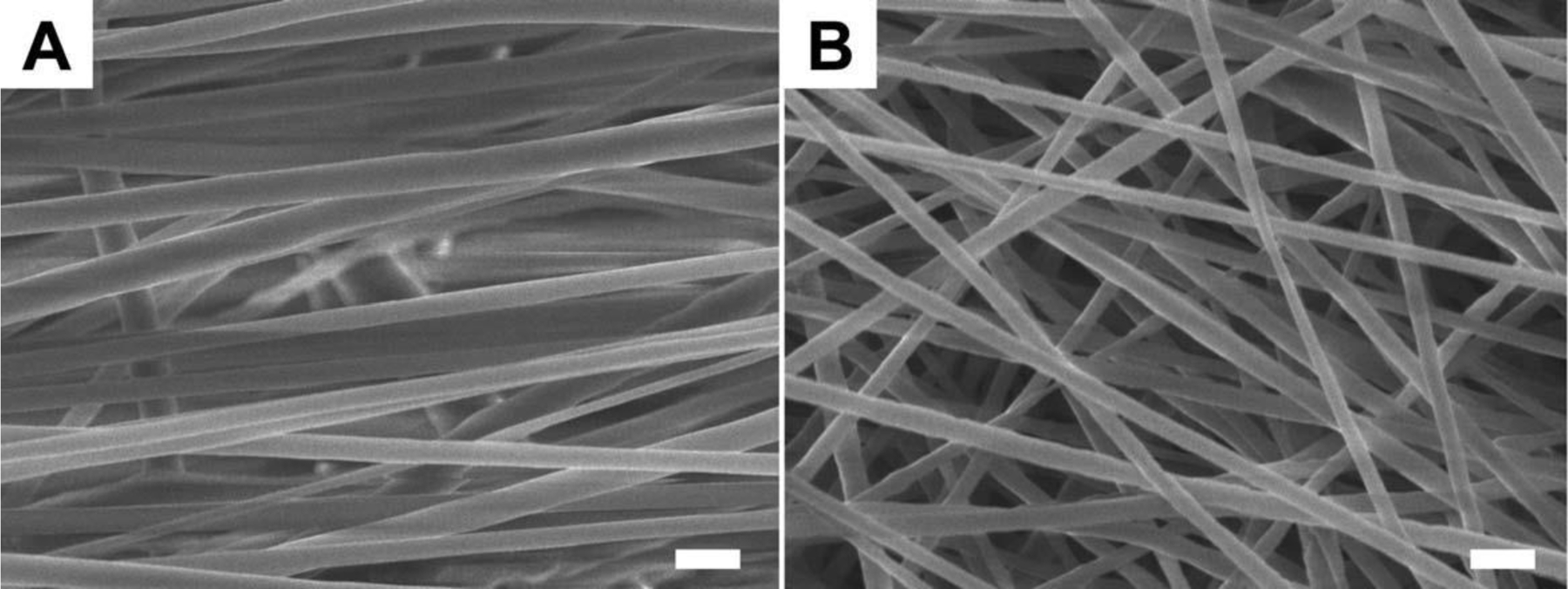
The morphologies of aligned and random PCL electrospun nanofibers. (A) Aligned fibers. (B) Random fibers. The scale bar is 1 µm.
Cell morphology and monocyte/macrophage density
Initial monocyte adhesion (day 0) on the four types of substrate surfaces is shown in Figure 2. On aligned fibers, monocytes exhibited a round shape indicating poor cell attachment onto the fiber surface. In contrast, monocytes on random fiber, film, and RGD-glass were well spread, demonstrating good cell adhesion. Monocytes were able to migrate easily between fibers and cell infiltration was observed on aligned fibers. However, no cell penetration was seen on the randomly-oriented nanofiber scaffolds.
Figure 2.
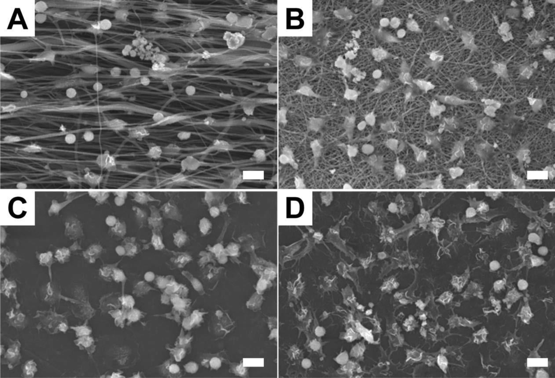
SEM images of monocytes on four types of surfaces at day 0 (2 h). (A) PCL aligned fibers. (B) PCL random fibers. (C) PCL film. (D) RGD-coated cover slip. The scale bar is 10 µm.
The monocyte/macrophage density on each substrate surface is summarized in Figure 3. The initial cell adhesion at day 0 (2 h) on the aligned fiber scaffolds was significantly lower than other three groups, while the random fiber scaffold was most supportive for monocyte adhesion. The cell density on the RGD-glass was slightly higher than on the PCL film, however, the difference was insignificant. Cell density decreased on all substrate surfaces over time as monocytes differentiated into macro-phages and then fused into foreign body giant cells in the presence of IL-4. In general, random fiber scaffolds showed a higher cell density over 10 days compared to aligned fiber scaffolds, film, and RGD-glass.
Figure 3.
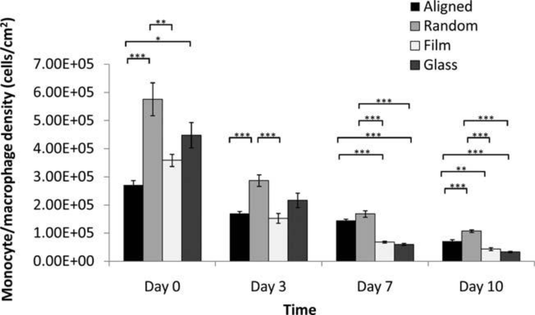
In vitro adherent monocyte/macrophage cell density on PCL nanofibers, PCL film, and RGD-glass as a function of time. (Mean ± SE) *p < 0.05, **p < 0.01, ***p < 0.001 for comparison between two data.
Foreign body reaction and fibrous capsule formation
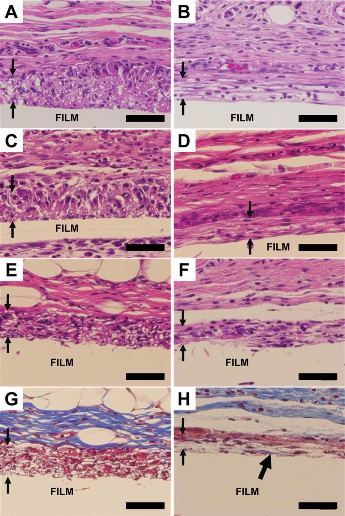
At week 4, fibrous capsules were formed on the surfaces of the three PCL scaffolds in vivo. An intense foreign body reaction was observed on random fiber surfaces [Fig. 4(C,D)] as evident from the presence of large foreign body giant cells and activated macrophages. In contrast, foreign body reaction was more quiescent on aligned fiber scaffolds and PCL film. On both fiber scaffolds, only a thin layer of collagen was deposited on the scaffold surface while a thick collagen layer formed on the film surface (Fig. 5). The thicknesses of fibrous capsules on aligned fiber scaffolds, random fiber scaffolds, and film were 7.55 ± 0.54 µm, 4.13 ± 0.31 µm, and 37.71 ± 0.25 µm, respectively.
Figure 4.
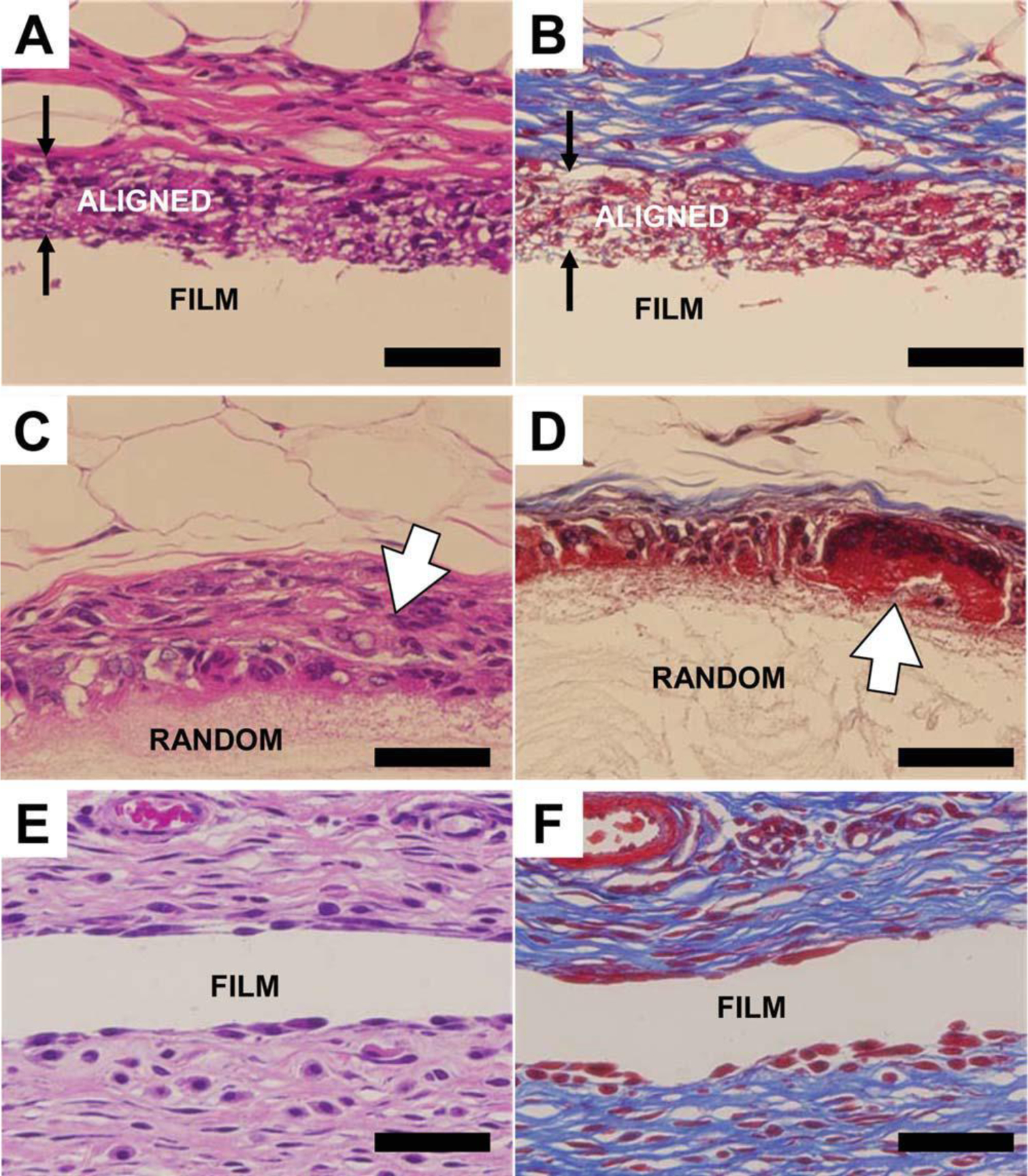
Histological images showing the fibrous capsules formed on PCL scaffold surfaces at week 4. (A,B) Aligned fibers. (C,D) Random fibers. (E,F) Film. Left, H and E staining. Right, Masson’s Trichrome staining. Three types of scaffolds are indicated on the images. The paired arrows indicate the aligned scaffold with cell infiltration. The open arrows show the strong macrophage/foreign body giant cell reaction on the random fiber scaffold. The scale bar is 50 µm.
Figure 5.
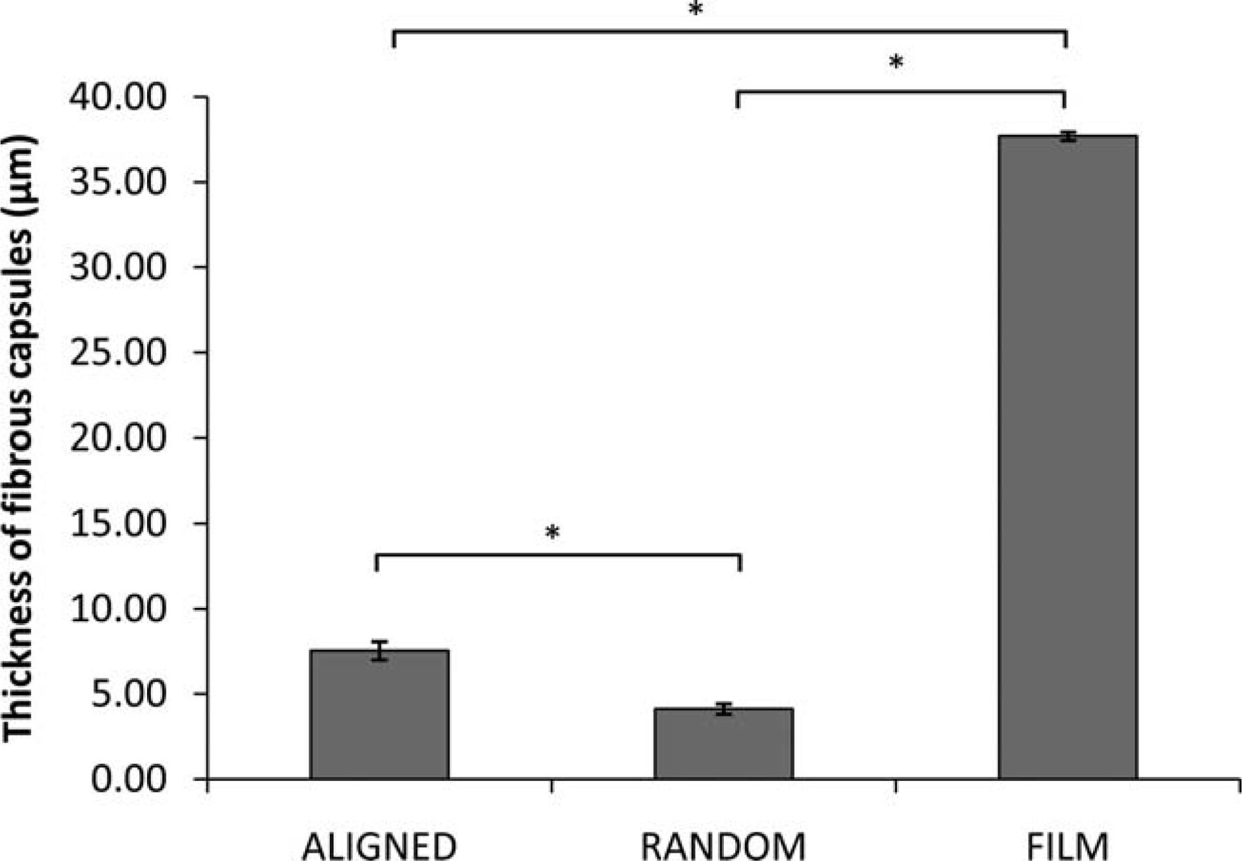
The thickness of fibrous capsules formed on different PCL scaffolds at week 4. (Mean ± SE)* Indicates statistical significance, p < 0.001.
Cellular infiltration
Cellular infiltration has rarely been reported on electrospun nanofibers. Electrospun fiber scaffolds usually demonstrate a two-dimensional behavior as the pore sizes on the surface are often too small for cells to penetrate in vitro. However, in vivo cellular infiltration was observed on aligned fiber scaffolds in this study (Fig. 6). Macrophages were able to migrate into aligned fiber scaffolds as early as 1 week after implantation [Fig. 6(A,B)]. A complete penetration was achieved in the aligned fiber scaffolds as a flat macrophage edge was observed, indicating the macrophages reached the surface of the supporting PCL film. Tissues surrounding the aligned fiber scaffolds were observed either parallel or perpendicular to the aligned fiber axis. With the parallel orientation, macrophages aligned along the fiber axis [Fig. 6(B,D,F,H)]. The perpendicular orientation showed no cell alignment as expected and the hollow spaces observed histologically between cells were cross-sections of PCL fibers [Fig. 6(A,C,E,G)]. Besides macrophage infiltration, fibroblasts also penetrated into the aligned fibers. During the inflammatory and healing processes, fibroblasts will migrate to the surfaces of the implants, and deposit collagen to develop fibrous capsules. In Figure 6(H), collagen deposition was identified inside the aligned fiber scaffold and on the surface of the supporting PCL film, suggesting that the aligned fibers are able to promote tissue-scaffold integration in vivo.
Figure 6.
Cell penetration on aligned fibers with perpendicular and parallel orientation. A,B: Week 1. C,D: Week 2. E,H: Week 4. G and H are Trichome staining of E and F, respectively. Left, perpendicular. Right, parallel. The paired arrows showed the apparent macrophage penetration into the aligned fibers. The thick black arrow head on Figure 6(H) shows collagen deposition. The scale bar is 50 µm. Aligned fibers were supported on PCL film.
In vivo biocompatibility assessment
PCL is a biocompatible polymer, which has been extensively studied as a tissue engineering material. In this work, the biocompatibility of aligned and random PCL fiber scaffolds and PCL film was clearly indicated by the very early resolution of acute and chronic inflammation (Table 2). No or minimal acute and chronic inflammation was seen at 2 weeks. Rapid onset of expected normal healing responses, i.e., granulation tissue and fibrous capsule formation, together with foreign body reaction were observed at week 2 and week 4, following acute and chronic inflammation. Different architecture of PCL scaffolds appeared to influence the healing process, with PCL film resulting in the least severe healing response, which resolved faster than the fibrous implants. Aligned fibers showed the next best bio-compatibility in terms of healing response and foreign body reaction while the random fiber scaffold had the slowest healing process.
Table 2.
In Vivo Biocompatibility: Inflammatory and Wound Healing Response
| Samples | Acute Inflammation | Chronic Inflammation | Granulation Tissue | Foreign Body Reaction |
|---|---|---|---|---|
| Week 1 | ||||
| Aligned | 0 | 0 | +1 | +2 |
| Random | 0 | 1 | +1.5 | +3.5 |
| Film | 0 | 0 | +1.5 | +2 |
| Week 2 | ||||
| Aligned | 0 | 0 | +2.5 | +2 |
| Random | 0 | 0 | +3 | +3 |
| Film | 0 | 0 | +2 | +2 |
| Week 3 | ||||
| Aligned | 0 | 0 | +1 | +1 |
| Random | 0 | 0 | +1 | +1.5 |
| Film | 0 | 0 | 0 | +1 |
Discussion
The foreign body reaction and fibrous capsule formation on the surface of an implant material are the important parameters in assessing its biocompatibil-ity. In this study, we investigated these responses with respect to different scaffold architectures made from a widely used biocompatible material, PCL. Topographic cues are able to influence cellular behavior independent of chemical signals.31 There-fore, the form of the medical device may ultimately affect its functionality. We fabricated three scaffolds,(aligned nanofiber, random nanofiber, and plain film) and evaluated monocyte/macrophage behavior in vitro and foreign body reaction and fibrous capsule formation in vivo.
Monocyte/macrophage showed different levels of adhesion on the three types of PCL scaffolds. Cell density was lowest on the aligned fiber scaffolds and highest on the random fiber scaffolds. From the SEM images (Fig. 2), aligned fibers exhibited larger inter-fiber spacing compared to randomly-oriented fibers. This larger inter-fiber spacing gave a smaller fiber surface area for initial cell adhesion and resulted in decreased cell density on the aligned fibers. On the other hand, cells showed the best attachment on the random nanofiber scaffold where the inter-fiber spacing was too small for cell infiltration and monocytes were able to spread on the sur-face. Compared to PCL film and RGD treated-glass surfaces, random nanofibers had a large surface-to-volume ratio for enhanced cell attachment.
The formation of the fibrous capsule is dependent on the properties of the implanted biomaterial and the thickness of the fibrous capsule can have a significant influence on the functionality of the implant. In the present study, we found that the fiber scaffold surface induced thinner fibrous capsule formation when compared to the smooth surface of the PCL film. The thickness of the fibrous capsule on the film surface was 37.7 ± 0.3 µm while that on the fiber scaffold surfaces was less than 8 µm. It has been reported that porous ceramic implants showed thinner fibrous capsules and healed faster than impervious ceramic implants.12 Scaffolds with lower porosity are more likely to induce dense fibrous capsule formation,32 so the thickness of the fibrous capsules can be greatly reduced when implants are more porous.33 In the present study, nanofiber scaffolds with highly porous structures and porosities larger than 80% greatly enhanced tissue-scaffold interactions and allow for cellular infiltration in the case of aligned scaffolds.
Randomly-oriented electrospun fibers with nano-ranged diameters showed limited ability for cell infiltration.34,35 However, in our study, in vivo cellular infiltration was observed on aligned fiber scaffolds with diameter of 506 ± 24 nm while the random PCL fiber scaffold failed to support cell penetration. Comparing the SEM images of aligned and random fibers (Fig. 1), we found that the random fibers have closer inter-fiber connections, which may restrict fiber movement. In contrast, aligned fibers possessed lesser inter-fiber connections allowing greater fiber flexibility and larger inter-fiber spaces that may have facilitated monocyte/macrophage infiltration [Fig. 2(A)]. Moreover, collagen was also found in the aligned fiber scaffold [Fig. 6(H)], indicating the infiltration of fibroblasts. Therefore, the aligned nanofiber scaffold demonstrated the capability of enhancing tissue-scaffold integration in vivo.
Intense macrophage and foreign body giant cell activity was found on random fiber scaffolds at all time points. Four weeks after implantation, large foreign body giant cells still remained on random fiber surfaces [Fig. 4(D)] indicating that the surface is less favorable in the host. Aligned fibers and film generated a mild foreign body reaction on the surface within 4 weeks and films induced the lowest macro-phages and foreign body giant cell activity. The bio-compatibility of the three types of PCL scaffolds was evaluated from the histology slides. For all scaffolds, acute inflammation was not observed. Acute inflammation normally resolves less than 1 week on bio-compatible biomaterials such as PCL. Chronic inflammation was only seen on random fibers at week 1 and resolved thereafter. Granulation tissue appeared on all scaffolds from week 1 and the intensity increased at week 2 as expected with the healing response, and finally dropped to nil. The random fiber scaffold triggered the strongest granulation tis-sue response while the least response was observed on the film. The foreign body reaction was similar to the granulation tissue response except that it did not disappear but become a stable tissue component around the implant. This reaction was most severe on the random fibers and least on the film, indicating that the healing process was slowest on the random fibers. The aligned fiber scaffold generated a moderate healing process in our study. Protein adsorption on the implanted material surface is the main reason for cell-associated inflammation and foreign body reaction.36,37 Increased surface area exposed to blood may attract more blood proteins onto the surface, resulting in a higher degree of cellular response. Nanofibers including random and aligned architectures exhibit high surface-to-volume ratio as compared to plain film. By absorbing more foreign body reaction-associated proteins onto the fiber scaffold surfaces the healing process would likely take longer. However, the difference in foreign body reactions between aligned and random fibers is still obscure. One possible reason is that the cellular infiltration into the aligned fibers reduced the severity of foreign body reaction. With improved tissue-scaffold integration, the aligned fiber scaffold appeared more “biocompatible” to the host.
Conclusion
This study demonstrated that nanotopographical cues have a significant influence on the in vitro and in vivo foreign body reaction to PCL nanofiber scaffolds. The electrospun PCL nanofibers with aligned and random orientation along with PCL films induced different inflammatory and wound healing responses. Aligned fiber scaffolds allowed cellular penetration in vivo and may serve as a promising scaffold for tissue engineering by minimizing host response and enhancing tissue-scaffold integration.
Acknowledgements
The partial funding support from NTU College of Engineering Startup grant and AcRF Tier 1 (RG36/07) is acknowledged by H. Q. Cao and S. Y. Chew. Support from NIH grant #EB006365–06A2 is gratefully acknowledged by K. McHugh and J. M. Anderson.
References
- 1.Anderson JM, Rodriguez A, Chang DT. Foreign body reaction to biomaterials. Semin Immunol 2008;20:86–100. [DOI] [PMC free article] [PubMed] [Google Scholar]
- 2.Hickey T, Kreutzer D, Burgess DJ, Moussy F. In vivo evaluation of a dexamethasone/PLGA microsphere system designed to suppress the inflammatory tissue response to implantable medical devices. J Biomed Mater Res 2002;61: 180–187. [DOI] [PubMed] [Google Scholar]
- 3.Turner RFB, Harrison DJ, Rojotte RV. Preliminary in vivo biocompatibility studies on perfluorosulphonic acid polymer membranes for biosensor applications. Biomaterials 1991;12: 361–368. [DOI] [PubMed] [Google Scholar]
- 4.Ratner BD. Reducing capsular thickness and enhancing angiogenesis around implant drug release systems. J Control Release 2002;78:211–218. [DOI] [PubMed] [Google Scholar]
- 5.Wood RC, Lecluyse EL, Fix JA. Assessment of a model for measuring drug diffusion through implant-generated fibrous capsule membranes. Biomaterials 1995;16:957–959. [DOI] [PubMed] [Google Scholar]
- 6.Nishi O, Nishi K, Sakka Y, Sakuraba T, Maeda S. Intercapsular cataract surgery with lens epithelial cell removal part IV: Capsular fibrosis induced by poly(methyl methacrylate). J Cataract Refr Surg 1991;17:471–477. [DOI] [PubMed] [Google Scholar]
- 7.Tang L, Thevenot P, Hu W. Surface chemistry influences implant biocompatibility. Curr Top Med Chem 2008;8:270–280. [DOI] [PMC free article] [PubMed] [Google Scholar]
- 8.Vardaxis NJ, Ruijgrok JM, Rietveld DC, Marres EM, Boon ME. Chemical and physical properties of collagen implants influence their fate in vivo as evaluated by light and confocal microscopy. J Biomed Mater Res 1994;28:1013–1025. [DOI] [PubMed] [Google Scholar]
- 9.Paul NE, Skazik C, Harwardt M, Bartneck M, Denecke B, Klee D, Salber J, Zwadlo-Klarwasser G. Topographical control of human macrophages by a regularly microstructured poly-vinylidene fluoride surface. Biomaterials 2008;29:4056–4064. [DOI] [PubMed] [Google Scholar]
- 10.Anderson JM. Biological responses to materials. Ann Rev Mater Res 2001;31:81–110. [Google Scholar]
- 11.Ward WK, Slobodzian EP, Tiekotter KL, Wood MD. The effect of microgeometry, implant thickness and polyurethane chemistry on the foreign body response to subcutaneous implants. Biomaterials 2002;23:4185–4192. [DOI] [PubMed] [Google Scholar]
- 12.Hulbert SF, Morrison SJ, Klawitter JJ. Tissue reaction to three ceramics of porous and non-porous structures. J Biomed Mater Res 1972;6:347–374. [DOI] [PubMed] [Google Scholar]
- 13.Parker JATC, Walboomers XF, Von Den Hoff JW, Maltha JC, Jansen JA. Soft-tissue response to silicone and poly-L-lactic acid implants with a periodic or random surface micropattern. J Biomed Mater Res 2002;61:91–98. [DOI] [PubMed] [Google Scholar]
- 14.DeFife KM, Colton E, Nakayama Y, Matsuda T, Anderson JM. Spatial regulation and surface chemistry control of mono-cyte/macrophage adhesion and foreign body giant. J Biomed Mater Res 1999;45:148–154. [DOI] [PubMed] [Google Scholar]
- 15.Flemming RG, Murphy CJ, Abrams GA, Goodman SL, Nealey PF. Effects of synthetic micro- and nano-structured surfaces on cell behavior. Biomaterials 1999;20:573–588. [DOI] [PubMed] [Google Scholar]
- 16.Dalby MJ, Marshall GE, Johnstone HJH, Affrossman S, Riehle MO. Interactions of human blood and tissue cell types with 95-nm-high nanotopography. IEEE Trans Nanobiosci 2002; 1:18–23. [DOI] [PubMed] [Google Scholar]
- 17.Popat KC, Leoni L, Grimes CA, Desai TA. Influence of engineered titania nanotubular surfaces on bone cells. Biomaterials 2007;28:3188–3197. [DOI] [PubMed] [Google Scholar]
- 18.Wojciak-Stothard B, Curtis A, Monaghan W, Macdonald K, Wilkinson C. Guidance and activation of murine macrophages by nanometric scale topography. Exp Cell Res 1996; 223:426–435. [DOI] [PubMed] [Google Scholar]
- 19.Rice JM, Hunt JA, Gallagher JA, Hanarp P, Sutherland DS, Gold J. Quantitative assessment of the response of primary derived human osteoblasts and macrophages to a range of nanotopography surfaces in a single culture model in vitro. Biomaterials 2003;24:4799–4818. [DOI] [PubMed] [Google Scholar]
- 20.Chew SY, Wen Y, Dzenis Y, Leong KW. The role of electrospinning in the emerging field of nanomedicine. C1urr Pharm Design 2006;12:4751–4770. [DOI] [PMC free article] [PubMed] [Google Scholar]
- 21.McNally AK, Jones JA, MacEwan SR, Colton E, Anderson JM. Vitronectin is a critical protein adhesion substrate for IL-4-induced foreign body giant cell formation. J Biomed Mater Res A 2008;86:535–543. [DOI] [PMC free article] [PubMed] [Google Scholar]
- 22.McNally AK, MacEwan SR, Anderson JM. a Subunit partners to b1 and b2 integrins during IL-4-induced foreign body giant cell formation. J Biomed Mater Res A 2007;82: 568–574. [DOI] [PubMed] [Google Scholar]
- 23.Jones JA, McNally AK, Chang DT, Qin LA, Meyerson H, Colton E, Kwon ILK, Matsuda T, Anderson JM. Matrix metalloproteinases and their inhibitors in the foreign body reaction on biomaterials. J Biomed Mater Res A 2008;84:158–166. [DOI] [PubMed] [Google Scholar]
- 24.Jones JA, Chang DT, Meyerson H, Colton E, Il KK, Matsuda T, Anderson JM. Proteomic analysis and quantification of cytokines and chemokines from biomaterial surface-adherent macrophages and foreign body giant cells. J Biomed Mater Res A 2007;83:585–596. [DOI] [PubMed] [Google Scholar]
- 25.McNally AK, Anderson JM. Complement C3 participation in monocyte adhesion to different surfaces. Proc Natl Acad Sci USA 1994;91:10119–10123. [DOI] [PMC free article] [PubMed] [Google Scholar]
- 26.McNally AK, Anderson JM. b1 and b2 integrins mediate adhesion during macrophage fusion and multinucleated foreign body giant cell formation. Am J Pathol 2002;160:621–630. [DOI] [PMC free article] [PubMed] [Google Scholar]
- 27.Voskerician G, Gingras PH, Anderson JM. Macroporous condensed poly(tetrafluoroethylene). I. In vivo inflammatory response and healing characteristics. J Biomed Mater Res A 2006;76:234–242. [DOI] [PubMed] [Google Scholar]
- 28.Rodriguez A, Voskerician G, Meyerson H, MacEwan SR, Anderson JM. T cell subset distributions following primary and secondary implantation at subcutaneous biomaterial implant sites. J Biomed Mater Res A 2008;85:556–565. [DOI] [PubMed] [Google Scholar]
- 29.Voskerician G, Shive MS, Shawgo RS, Von Recum H, Anderson JM, Cima MJ, Langer R. Biocompatibility and biofouling of MEMS drug delivery devices. Biomaterials 2003;24:1959–1967. [DOI] [PubMed] [Google Scholar]
- 30.Voskerician G, Shawgo RS, Hiltner PA, Anderson JM, Cima MJ, Langer R. In vivo inflammatory and wound healing effects of gold electrode voltammetry for MEMS micro-reservoir drug delivery device. IEEE Trans Bio Med Eng 2004; 51:627–635. [DOI] [PubMed] [Google Scholar]
- 31.Su WT, Yang JY, Lin CD, Chu IM. Control cell behavior on physical topographical surface. JPN J Appl Phys 1 2004;43: 3806–3809. [Google Scholar]
- 32.Salzmann DL, Kleinert LB, Berman SS, Williams SK. The effects of porosity on endothelialization of ePTFE implanted in subcutaneous and adipose tissue. J Biomed Mater Res 1997;34:463–476. [DOI] [PubMed] [Google Scholar]
- 33.Jansen JA, von Recum AF, van der Waerden JPCM, de Groot K. Soft tissue response to different types of sintered metal fiber-web materials. Biomaterials 1992;13:959–968. [DOI] [PubMed] [Google Scholar]
- 34.Baker BM, Gee AO, Metter RB, Nathan AS, Marklein RA, Burdick JA, Mauck RL. The potential to improve cell infiltration in composite fiber-aligned electrospun scaffolds by the selective removal of sacrificial fibers. Biomaterials 2008;29: 2348–2358. [DOI] [PMC free article] [PubMed] [Google Scholar]
- 35.Pham QP, Sharma U, Mikos AG. Electrospun poly (e-caprolactone) microfiber and multilayer nanofiber/microfiber scaffolds: Characterization of scaffolds and measurement of cellular infiltration. Biomacromolecules 2006;7:2796–2805. [DOI] [PubMed] [Google Scholar]
- 36.Pankowsky DA, Ziats NP, Topham NS, Ratnoff OD, Anderson JM. Morphologic characteristics of adsorbed human plasma proteins on vascular grafts and biomaterials. J Vasc Surg 1990;11:599–606. [PubMed] [Google Scholar]
- 37.Tang L, Ugarova TP, Plow EF, Eaton JW. Molecular determinants of acute inflammatory responses to biomaterials. J Clin Invest 1996;97:1329–1334. [DOI] [PMC free article] [PubMed] [Google Scholar]