Abstract
Molten salts for use as heat transfer fluids in concentrated solar or nuclear power plants have experienced a resurgence over the past decade with a special focus on chloride-based salt mixtures, particularly for use in concentrating solar power and fast-spectrum nuclear reactors. Salt purification, specifically oxide removal, is required even for high purity commercial salts and can be achieved using many different methods. Carbochlorination, however, proves most effective according to thermodynamics and produces a gaseous byproduct easily removed from the salt. A variety of carbochlorinating reagents and reagent combinations were evaluated for thermodynamic favorability in the removal of common impurities in MgCl2-based feedstock or coverage gases used in industrial systems. Carbon tetrachloride exhibited superior purification thermodynamics above the melting point of common MgCl2-based salt compositions. Salt with composition of 68 : 32 mol% KCl : MgCl2 was purified on the kilogram scale by sparging with carbon tetrachloride, reducing dissolved oxide to trace levels (42 μmol MgO/kg salt). Interestingly, the lower purity salts exhibited magnesium and oxygen presence along grain boundaries in the corrosion layers while the purified salts did not, highlighting the need for decreased oxide content. The lessened corrosivity of the highly purified salt suggests a proper salt treatment may reduce dependence on specialized materials for use with molten salts.
The purification of molten salts by carbochlorination produces low oxide content salt minimizing corrosion in 316L stainless steel and alloy-N.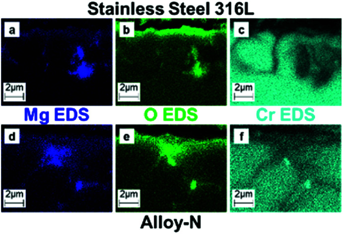
Introduction
High temperature molten salts exhibit properties ideally suited for use as heat transfer fluids (HTFs) in solar thermal collectors, nuclear reactors, and heat recovery systems in factories.1–7 Mixed molten salts have high heat-capacity, are chemically stable at elevated temperatures, and exhibit a tailorable melting point through compositional changes. A large body of work has been performed on fluoride, nitrate, and carbonate salt mixtures, such as lithium beryllium fluoride (FLiBe),8–11 sodium potassium nitrate (NaNO3–KNO3),7,12–14 lithium potassium carbonate (LiKCO3),15,16 and many others.17–19 Chloride-based salt mixtures have several advantages over nitrates, carbonates, and fluorides. They have higher maximum operation temperatures than their nitrate or carbonate counterparts, improving reactor efficiency. Chloride salts are cheaper and more abundant than fluorides, resulting in their favourability for large scale use. Chloride salts already are used as feedstock for the Kroll process, alloy heat treatments, and recycling of spent nuclear fuel.20
Molten chlorides are becoming increasingly important as HTFs with the push toward carbon-free energy sources. As HTFs, molten chlorides need to freely flow throughout the vessel without significantly corroding the containment material. Impurity-driven corrosion is the primary mechanism with H2O as the major source.21 Hydrated MgCl2 decomposes, i.e. hydrolyzes, when dehydrated beyond the monohydrate, producing MgOHCl above ∼300 °C and MgO above ∼550 °C.22 In addition to the oxide impurities, residual impurities arising from the MgCl2 hydrolysis can result in degradation of the alloy. Research to combat corrosion has focused on three major aspects: alloy improvement, redox control, and cladding layer development. Ni-based alloys show particularly strong corrosion resistance to molten salts. Low-chromium nickel alloys have been developed for use with molten salts, most famously alloy-N, developed for use with molten fluoride nuclear reactor fuel salt.23 Redox control utilizes a metal or reducing salt to preferentially corrode before the containment material.9 A similar approach to redox control employs a Mg anode to electrolytically reduce the corrosivity of MgCl2-based salts.24 For additional stability, cladding layers to protect the underlying structural material were created to reduce corrosion.25 Little work has been done to correlate chloride salt purification techniques to corrosivity. This is problematic as Raiman and Lee's extensive review of molten chloride and fluoride corrosion studies relate how purification influences mass loss.17
Purification of molten chlorides to remove dissolved oxide typically utilized one of three methods: simple drying, vacuum distillation, and chemical purification.26–28 Many of the alkali chlorides can be heated under vacuum to remove surface moisture and subsequently melted to remove dissolved moisture. However, heating under vacuum produces impure MgCl2 because of hydrolysis.22 Double distillation of MgCl2 under vacuum produces high purity salt by leaving low vapor pressure impurities, such as MgO.27,29 While distillation generates high purity salt, this represents an engineering challenge that increases cost thereby decreasing economic viability. Chemical purification reagents, such as hydrogen chloride (HCl) or ammonium chloride (NH4Cl), are currently used to purify MgCl2-based feedstock for magnesium production via electrolysis.30,31 In fact, the ammonium carnallite arising from mixing NH4Cl with MgCl2 has been utilized to generate magnesium chloride with no hydroxide.32 Magnesium electrolysis can tolerate MgCl2 saturated with MgO, but corrosion rates are increased by dissolved oxide.33 Carbochlorination is a well-known process for removing oxide impurities from metals.34 There are a variety of carbochlorination methods: carbon and chlorine (C + Cl2),35 carbon monoxide and chlorine (CO + Cl2),35 and phosgene (COCl2).36 Chen et al. demonstrated carbon tetrachloride (CCl4) removes trace oxide from haloaluminate melts as efficiently as phosgene with safer handling protocols.37
In this work, we calculated the Gibbs free energy of reaction from JANAF data38 for a variety of purification reagents to determine their ability to remove impurities commonly found in MgCl2-based salt mixtures. Using the information from the thermodynamic studies and previous reports,27,37,39 we purified 68 : 32 mol% KCl : MgCl2 and compared the resulting purities. The native oxide content was determined with base neutralization titrations using standardized acid. Different levels of KCl : MgCl2 purity were compared to correlate chemical impurities of the fused salt and the subsequent corrosion of stainless steel 316L (SS316L) and alloy-N.
Experimental
Chemicals
Ammonium chloride (NH4Cl, Fisher Scientific, 99.6% assay, A661), carbon tetrachloride (CCl4, Acros Organics 99% assay, 14 817), Drierite™ (4 mesh with indicator, Acros Organics), hydrochloric acid (HCl, Fisher Scientific, 32–35% Optima grade, A466), potassium chloride (KCl, Fisher Scientific 99.4% assay, P217), potassium hydroxide (KOH, Fisher Scientific, 85% flakes, P246), phosphorous pentoxide (P2O5, JT Baker 99% assay, 9374), metallic zinc (Zn, Fisher Scientific, certified ACS mossy, Z11) sodium hydroxide (NaOH, Millipore-Sigma, 99.99% semiconductor grade pellets, 306576), magnesium chloride (MgCl2, Alfa Aesar, 99% anhydrous, 12315) were used as received. Ultra-high purity (UHP) argon (Ar) and 4% hydrogen in argon (Ar/4% H2) was supplied by Airgas. The Orion™ AquaPro™ pH Combination Electrodes (9104APWP) and Orion™ pH Buffers (pH 4, 7, and 10, 910199) were purchased from Fisher Scientific.
Salt purification
Low purity salt was prepared by mixing and fusing as-delivered KCl and MgCl2 at 850 °C. 375 g of KCl and 225 g of anhydrous MgCl2 were physically mixed and loaded into a quartz crucible in air. The crucible was loaded into a quartz reactor with three 24/40 tapered joints, placed in a Lindberg Blue M tube furnace (HTF55322A furnace, CC58114A controller) set vertically, and purged with dried UHP argon for 15 minutes. On the center port, an o-ring joint was utilized to insert the sparge tube while maintaining a gas-tight seal. On the outlet port, due to plugging by evolved solids, a bump trap often utilized with rotary evaporators was used to provide a collection point for accumulating carbon or ammonium chloride. The flow was monitored using a 1 L min−1 PTFE rotameter (Omega, FL-3103SA) set to 500 mL min−1. The UHP Ar was dried with P2O5 layered with Drierite™ followed by a trap with only Drierite™. The reactor exhausted into an empty vacuum (“bump”) trap followed by a DI water (H2O) trap with mossy zinc (magnesium turnings are an acceptable substitute for mossy zinc) then a 5.0 M KOH bath. To thoroughly mix the molten salt, the middle port was used for the sparge tube with the CCl4 bubbler bypassed (see Fig. S1†). Initial sparge tubes were open-ended graphite; however, the wear on the graphite resulted in significant breakage. After several iterations involving an open-ended quartz tube, a quartz tube (8 × 12 mm) sealed on one end with six rows of 1 mm holes drilled into the sealed end to a height of 1 inch to diffuse the gas into the molten salt. The sparge tube was initially out of the salt and flowing dried Ar. Following the 15 minute Ar purge, the reactor was heated to 850 °C at 10 °C min−1. At temperature, the sparge tube was lowered into the molten salt and Ar flowed for 1 hour. After thorough mixing, the sparge tube was removed from the salt with Ar flowing to maintain an inert atmosphere. Note, the o-ring may fuse to the quartz tube creating a break hazard as the tube will be hot requiring appropriately-rated thermal protection with cut-proof gloves. The furnace was naturally cooled, and the reactor was transferred to an inert Ar glove box without being exposed to air.
Initial MgCl2 purification was achieved by utilizing the carnallite method initially reported by Young, et al.27 and described by Zhang et al.31 500 g of anhydrous MgCl2 and 250 g of NH4Cl were physically mixed and loaded into a quartz crucible in air. For the carnallite method, the reactor only used two ports: the Ar inlet and the exhaust. Following the 15 minute Ar purge, the furnace was heated to 450 °C at 10 °C min−1 and held at temperature for 2 hours to remove moisture and some oxide. The furnace was then heated to 750 °C at 10 °C min−1 and held for 1 hour to remove unreacted NH4Cl. The furnace was naturally cooled, and the reactor was transferred to an inert Ar glove box without being exposed to air.
The KCl was purified by sparging with CCl4. Specifically, 600 g of KCl was loaded into a quartz crucible. The crucible was loaded into the quartz reactor, placed in the furnace, and purged with dried UHP Ar for 15 minutes. For sparging, the middle port was used for the sparge tube with the CCl4 bubbler bypassed (see Fig. S1†). The sparge tube was out of the salt and flowing dried Ar. The reactor was heated to 850 °C at 10 °C min−1. At temperature, the sparge tube was lowered into the molten salt and CCl4 flowed for 3 hours. The CCl4 bubbler was bypassed so only Ar flowed into the reactor and held for 30 minutes. The gas was switched to Ar/4% H2, held for 3 hours, and then switched back to Ar for 30 minutes. Following salt purification, the sparge tube was removed from the salt and the furnace was naturally cooled to room temperature. The reactor was transferred to an inert glove box for further use. For MgCl2, the same basic procedure was followed. Approximately 600 g of previously purified (carnallite method) MgCl2 was loaded into the reactor inside the glove box. The MgCl2 was sparged with CCl4 at 850 °C for ∼60 hours followed by 30 minutes Ar, ∼60 hours Ar/4% H2, and finished with Ar for 30 minutes.
The moderate purity salt was prepared by mixing pre-cleaned (CCl4-sparged) KCl and pre-cleaned (CCL4-sparged) MgCl2. For this, 500 g of sparged KCl and 300 g of sparged MgCl2 were weighed in a glove box and loaded into a quartz crucible. The crucible was loaded into the quartz reactor, attached to the dried Ar line without exposure to air, and placed in the furnace. The salt was thoroughly mixed following the same procedure as the low purity salt. The moderate purity was transferred to an inert Ar glove box without being exposed to air and 200 g were separated for corrosion experiments. The high purity salt was made by sparging the remaining moderate purity salt (∼600 g) for 55 hours with CCl4 and 55 hours with Ar/4% H2 to reduce the amount of oxide to trace amounts.
Oxide quantification
200 mL of deionized water (18.2 MΩ) was poured into a 500 mL three-neck round bottom flask and degassed with Ar for 30 minutes. Approximately 2 g of salt was weighed in the glove box and the value was recorded for accuracy. The salt was added to the degassed and deionized water and allowed to dissolve for 15 minutes. An Orion™ AquaPro™ pH Combination Electrode was calibrated with Orion™ pH Buffers (pH 4, 7, and 10) to assure accuracy and inserted into the salt solution. The initial pH was recorded, and the salt solution was titrated with 0.01 M HCl via micropipettes that were pre-calibrated using water and an analytical balance. An addition was made every 5 minutes to allow ample time for equilibration. The amount of titrant was adjusted to change the pH by ∼0.2 pH units every addition. The titration was complete at ∼6 pH and the amount of titrant needed to reach pH 7 was determined. The oxide content was calculated using eqn (1) assuming all basicity was from MgO.
 |
1 |
where Vtitrant is the volume of titrant to reach pH 7 in μL and msalt is the mass of salt in grams.
Corrosion testing
Metal coupons of SS316L and alloy-N were polished to a 600-grit finish, rinsed with acetone, and dried. The weights and dimensions were recorded and then loaded into 200 mm long, 8/12 mm (ID/OD) quartz ampules with salt inside an inert glovebox. The salt consisted of three grams (3 g) of varying purity (low, moderate, and high purity) KCl : MgCl2 (68 : 32 mol%). Swagelok® Ultra-Torr fittings with Swagelok® needle valves were attached to each ampule and vacuum was established in the tube. The quartz ampules were flame-sealed under vacuum. The sealed ampules were heated in a Barnstead-Thermolyne box furnace (model FB1415M) at 20 °C min−1 to 700 °C and held for 100 hours. The furnace was naturally cooled, and the metal coupons were removed by breaking the ampules. The coupons were sonicated in deionized water (18.2 MΩ) for 1 hour and rinsed. The coupons were sonicated in fresh deionized water (18.2 MΩ) for 30 minutes twice more. Following the final rinse, the coupons were rinsed with methanol and dried at 120 °C in air for 5 minutes and cooled to room temperature. The coupons were weighed with a Mettler Toledo model XP205 balance with an accuracy of ±0.04 mg (<0.02 mg cm−2). After weighing, samples were cross-sectioned, metallographically mounted, and imaged. Samples were characterized with scanning electron microscopy (SEM) and energy dispersive spectroscopy (EDS) mapping on a Hitachi S-4800 equipped with EDAX hardware.
Results and discussion
As-received salt does not meet the level of purity necessary to prevent considerable corrosion.33 Most MgCl2 purchased directly from vendors contain ∼0.4% water, both crystallized (MgCl2·nH2O, where n = 1, 2, 4, or 6) and surface adsorbed. Each water molecule can directly react with the containment material according to eqn (2) or indirectly by HCl generated from hydrolysis of MgCl2 according to reaction (3).
| xM + yH2O → MxOy + yH2 | 2 |
| M + xHCl → MClx + x/2H2 | 3 |
Additionally, anhydrous MgCl2 purchased from a variety of vendors was found to contain dissolved oxygen in the form of MgO (∼0.2 wt%). Oxygen is dissolved in MgCl2-melts by complexation of two MgCl2 molecules.40 Oxide and hydroxide have been linked to an increase in the corrosion rate, making their removal crucial.33
Carbochlorination is an attractive method for purification because it yields a gaseous product that does not remain in the salt while still removing oxide to trace levels. Carbochlorination utilizes four different reagents (or reagent combinations): carbon and chlorine (C + Cl2), carbon monoxide and chlorine (CO + Cl2), phosgene (COCl2), and carbon tetrachloride (CCl4). The original method, C + Cl2, required solid carbon suspended in the material (salt in this case). The use of solid precursors is not desired due to the need to remove residual unreacted solid, i.e. carbon. Therefore, C + Cl2 was not considered for comparison. The other three reagents (or reagent combination) utilize similar reactions to perform carbochlorination (eqn (4)–(6)).
| CO + Cl2 + MgO → CO2 + MgCl2 | 4 |
| COCl2 + MgO → CO2 + MgCl2 | 5 |
| 1/2CCl4 + MgO → 1/2CO2 + MgCl2 | 6 |
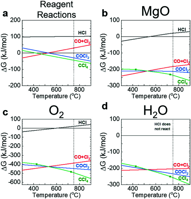
Thermodynamic favourability of purifying MgCl2-based salts with HCl, CO + Cl2, COCl2, and CCl4 was determined to assess the efficacy of each reagent. The low ΔG for HCl, with a positive ΔG above approx. 525 °C, suggest HCl is not favourable to remove MgO and thus was not included in the corrosion study. Since MgO is more energetically favourable than MgOHCl above ∼550 °C, it was used to assess impurities caused by hydrolysis. Evaluation of carbochlorination and HCl was performed to compare carbochlorination to purification methods already utilized. The thermodynamic data were calculated using Gibbs free energy of formation 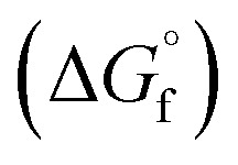 to determine the favourability of reaction using JANAF tables from NIST.38 The Gibbs free energy for the reaction (ΔG) was calculated using the format in eqn (7).
 |
7 |
where 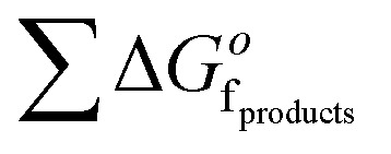 is the sum of the
 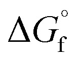 of the products and
 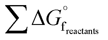 is the sum of
 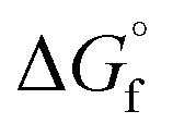 of the reactants. The ΔG was calculated for a mixture of potassium oxide (K2O) and MgCl2 following the format in eqn (7) and the stoichiometry of eqn (8) to determine the equilibrium constant (eqn (9)).
| K2O + MgCl2 → 2KCl + MgO | 8 |
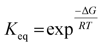 |
9 |
where Keq is the equilibrium constant, R is the ideal gas constant, and T is the temperature in Kelvin. The resulting equilibrium constant for the reaction in eqn (8) is ∼1019 at 750 °C, suggesting the predominant species of oxide in the salt is MgO. Common impurities in the Ar gas supply, such as O2 and H2O, were also considered.
The change in Gibbs free energy (ΔG) for the decomposition of HCl, COCl2, and CCl4 (see ESI† for equations) were calculated to determine reagent stability (Fig. 1a). The ΔG for CO + Cl2 was calculated as the reverse reaction of COCl2 since CO or Cl2 are not favoured to decompose further. The remaining reaction equations are in the ESI.† As seen in Fig. 1b–d, CCl4 (green line) becomes the thermodynamically favoured purifying reagent for the selected impurities above ∼525 °C. The decomposition of CCl4 further enhances the CO and CO2 formation driving the deoxygenation of the salt (Fig. S2†). Therefore, the sparging temperature was set to 750 °C to ensure ample decomposition of CCl4 and increase the favourability of purification.
Fig. 1. Plots of ΔG versus temperature for the purifying reagents (a) and their reaction with MgO (b), O2 (c), and H2O (d). The purifying reagents are HCl (grey), CO + Cl2 (red), COCl2 (blue), and CCl4 (green). The vertical dashed lines indicate the temperature selected for sparging.
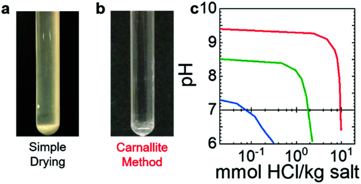
The low-purity salt, made by simply heating to 850 °C, stratified upon solidification. Stratification is an indication of MgO formation (Fig. 2a), because MgO was generated during fusing. The as-received “anhydrous” magnesium chloride lot analysis suggests 0.39–0.40% moisture (Alfa Aesar, product 12315, Lot W07D102). The water in the as-received MgCl2 caused it to hydrolyze, forming MgOHCl and, subsequently, MgO upon heating.41 The strata developed when MgO reached saturation and settled to the bottom while the salt melt remained on top.40 The resulting oxide content ranged from 10 000–30 000 μmol kg−1. Using the carnallite method31 reduces the amount of MgO formation to below the solubility limit in MgCl2 (Fig. 2b). Solid MgO decreases the efficiency of oxide removal because the reaction is limited to dissolved oxide. Precipitated MgO would slow the purification due to the continuous dissolution of solid MgO into the melt, governed by the dissolution kinetics. Hence, reducing MgO to below the solubility limit makes subsequent purification easier and more efficient.
Fig. 2. (a and b) Images of KCl : MgCl2 (68 : 32 mol%) purified using heat only (a) and using the carnallite method (b). (c) pH versus log10 of titrant comparing salt purified with the carnallite method (red), mixing pre-sparged salts (green), and sparging with CCl4 for 60 hours (blue). Sparging with CCl4 was performed at 750 °C followed by 30 minutes sparging with Ar only, equal time sparging with Ar/4%H2 (60 hours), and a final 30 minute sparge with Ar only.
The KCl and MgCl2 were purified separately to prevent moisture from KCl hydrolysing MgCl2 and forming MgO upon dehydration. The salt was fused in the same ratio and no stratification occurred (moderate purity, Fig. 2c, green). This salt was also sparged with CCl4 and subsequently Ar/4%H2 for an additional 55 hours to further remove dissolved oxide as well as residual chlorinated species, e.g. HCl and chlorinated carbonaceous residue. The additional sparge removed dissolved MgO to trace levels (Fig. 2c, blue). The resulting oxide contents for the moderate and high purity salts were 915 and 42 μmol kg−1, respectively.
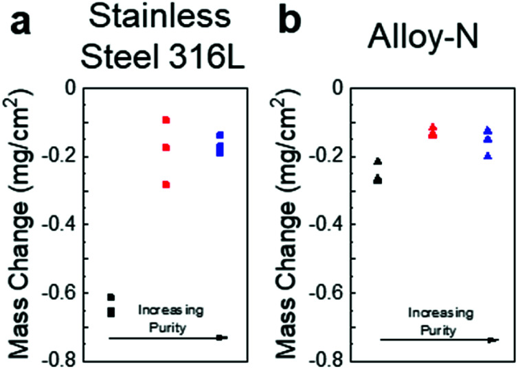
Coupons of SS316L and alloy-N were exposed to salts of three different purities (low, moderate, and high with oxide contents of ∼20 000, 900, and 50 μmol kg−1, respectively) for 100 hours at 700 °C. The mass change for the SS316L samples showed significantly increased corrosion for the low purity salt versus the moderate/high purity salts (Fig. 3a). The moderate and high purity salts showed similar mass loss, but the high purity salt was more consistent. The alloy-N sample showed similar trends, but with less difference between the low purity (as-received, fused) and purified salts (Fig. 3b). Interestingly, the mass loss data indicated little difference between the moderate and high purity samples. Alloy-N, a nickel-based superalloy, was designed specifically to contain molten fluoride salts; therefore, it was expected to perform better than stainless steel. An especially interesting result is the large difference between materials in the untreated salt, and the relatively small difference between the performance of the materials in the purified salts. This suggests material selection may be important in aggressive environments, but properly prepared salts may lessen the differences between materials, enabling the use of less expensive materials as salt-facing structural components.
Fig. 3. (a) Mass change data for SS316L coupons exposed to salt of low (black), moderate (red), and high (blue) purities. (b) Mass change data for alloy-N coupons exposed to salt of low (black), moderate (red), and high (blue) purities.
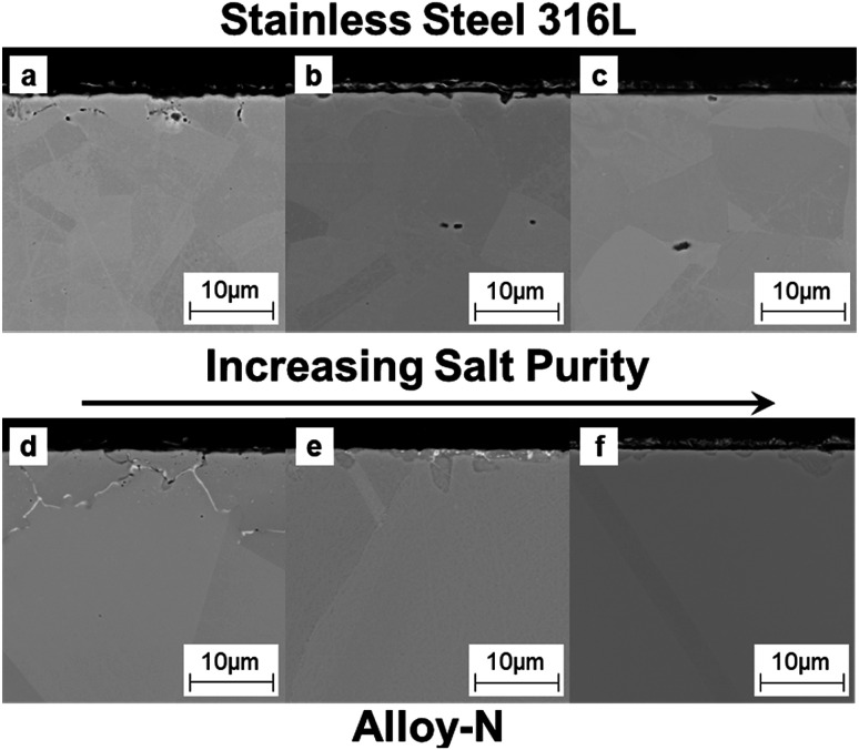
The corroded coupons were cross-sectioned and characterized via scanning electron microscopy (SEM) and energy dispersive spectroscopy (EDS). Cross-sectional SEM showed a similar trend to the mass loss data (Fig. 4); increasing salt purity decreased the amount of corrosion. The low purity salt attacked the metal more than the higher purity salts and SS316L more than alloy-N (Fig. 4a and d, respectively). EDS revealed significant depletion of chromium (Cr) along the grain boundaries (Fig. S3 and S4†). Additionally, EDS maps of Mg and O of coupons exposed to low purity salt showed MgO deposited in the sample where Cr was depleted (Fig. S5†). In the case of low purity salt saturated with MgO, mass loss data does not accurately represent the severity of corrosion.
Fig. 4. (a–c) Cross-sectional SEM images for SS316L coupons exposed to salt of low (a), moderate (b), and high (c) purities. (d–f) Cross-sectional SEM images for Hast-N coupons exposed to salt of low (d), moderate (e), and high (f) purities.
Cross-sectional SEM and EDS also revealed subtle differences in corrosion between the moderate and high purity salts. The salt of moderate purity (Fig. 4b and e) exhibited more surface roughening than the salt of high purity (Fig. 4c and f). In particular, the region of attack exhibited increased Cr depletion (Fig. S3 and S4†) with minimal change to the base metal (Fe for SS316L and Ni for alloy-N). The level of Cr depletion was deeper than the base alloy, an observation consistent with previous reports.23
Conclusions
Chloride-based thermal energy storage salts were purified on the 0.5–1 kilogram scale via carbochlorination using carbon tetrachloride as the chlorination reagent. This resulted in a reduced dissolved oxide content and subsequently, reduced oxide-based corrosion of 316L stainless steel and alloy-N. This work demonstrates that oxygen content in chloride salts cannot be ignored, even when considered insoluble as with MgO, during alloy or salt selection. The ability to generate salts with varying purity enables correlation of the oxide content to the observed corrosion by both granular attack and generalized corrosion. Data from exposures with low purity salt saturated with oxide demonstrated that mass change was not necessarily a good indicator of corrosion due to MgO deposition in the void space left by Cr depletion. As such, mass change data should be coupled to cross-sectional imaging techniques like SEM and EDS. Interestingly, the presence of MgO along the grain boundary may suggest a role for MgO in Cr depletion mechanisms and is under further investigation. Higher purity salt exhibited a decrease in corrosivity, especially in SS316L. Since increased purity, i.e. lowered oxide content, decreases the corrosivity of salt, careful control of salt chemistry may enable the use of cheaper materials that are readily available in place of designer alloys at premium prices. High purity salt also serves as an effective baseline to study the effects of common impurities, such as oxygen, bromide, boron, and trace metals, including impurities collected in service, such as corrosion and fission products. Additionally, the use of high purity salt enables the study of how individual impurities affect the corrosion behaviour and thermophysical properties, both in static and flowing conditions.
Conflicts of interest
There are no conflicts to declare.
Supplementary Material
Acknowledgments
This research was sponsored by the Laboratory Directed Research and Development Program of Oak Ridge National Laboratory, managed by UT-Battelle, LLC, for the U. S. Department of Energy. S.D. was supported as part of the Molten Salts in Extreme Environments, an Energy Frontier Research Center funded by the U.S. Department of Energy (DOE), Office of Science, Basic Energy Sciences (BES). The authors thank Mr Adam Willoughby for assistance in alloy preparation and Ms Tracie Lowe for the assistance with microscopy. This manuscript has been authored by UT-Battelle, LLC, under contract DE-AC05-00OR22725 with the US Department of Energy (DOE). The US government retains and the publisher, by accepting the article for publication, acknowledges that the US government retains a nonexclusive, paid-up, irrevocable, worldwide license to publish or reproduce the published form of this manuscript, or allow others to do so, for US government purposes. DOE will provide public access to these results of federally sponsored research in accordance with the DOE Public Access Plan (http://energy.gov/downloads/doe-public-access-plan).
Electronic supplementary information (ESI) available. See DOI: 10.1039/c9ra03133b
Notes and references
- Weinstein L. A. Loomis J. Bhatia B. Bierman D. M. Wang E. N. Chen G. Concentrating Solar Power. Chem. Rev. 2015;115(23):12797–12838. doi: 10.1021/acs.chemrev.5b00397. [DOI] [PubMed] [Google Scholar]
- Mehos M., Turchi C., Vidal J., Wagner M., Ma Z., Ho C., Kolb W., Andraka C., and Kruizenga A., Concentrating Solar Power Gen3 Demonstration Roadmap; NREL/TP-5500-67464; National Renewable Energy Laboratory (NREL), Golden, CO, 2017, p. 127 [Google Scholar]
- Le Brun C. Molten salts and nuclear energy production. J. Nucl. Mater. 2007;360(1):1–5. doi: 10.1016/j.jnucmat.2006.08.017. [DOI] [Google Scholar]
- LeBlanc D. Molten salt reactors: A new beginning for an old idea. Nucl. Eng. Des. 2010;240(6):1644–1656. doi: 10.1016/j.nucengdes.2009.12.033. [DOI] [Google Scholar]
- Uhlir J. Chemistry and technology of Molten Salt Reactors - history and perspectives. J. Nucl. Mater. 2007;360(1):6–11. doi: 10.1016/j.jnucmat.2006.08.008. [DOI] [Google Scholar]
- Ding W. J. Shi H. Xiu Y. L. Bonk A. Weisenburger A. Jianu A. Bauer T. Hot corrosion behavior of commercial alloys in thermal energy storage material of molten MgCl2/KCl/NaCl under inert atmosphere. Sol. Energy Mater. Sol. Cells. 2018;184:22–30. doi: 10.1016/j.solmat.2018.04.025. [DOI] [Google Scholar]
- Bonk A. Sau S. Uranga N. Hernaiz M. Bauer T. Advanced heat transfer fluids for direct molten salt line-focusing CSP plants. Prog. Energy Combust. Sci. 2018;67:69–87. doi: 10.1016/j.pecs.2018.02.002. [DOI] [Google Scholar]
- Keiser J. R., DeVan J. H., and Manning D. L.The Corrosion Resistance of Type 316 Stainless Steel to Li2BeF4; ORNL/TM-5782, Oak Ridge National Laboratory, Oak Ridge, TN, 1977, p. 25 [Google Scholar]
- Zhang J. S. Forsberg C. W. Simpson M. F. Guo S. Q. Lam S. T. Scarlat R. O. Carotti F. Chan K. J. Singh P. M. Doniger W. Sridharan K. Keiser J. R. Redox potential control in molten salt systems for corrosion mitigation. Corros. Sci. 2018;144:44–53. doi: 10.1016/j.corsci.2018.08.035. [DOI] [Google Scholar]
- Zheng G. Q. Sridharan K. Corrosion of Structural Alloys in High-Temperature Molten Fluoride Salts for Applications in Molten Salt Reactors. JOM. 2018;70(8):1535–1541. doi: 10.1007/s11837-018-2981-2. [DOI] [Google Scholar]
- Simpson M. F. Smolik G. R. Sharpe J. P. Anderl R. A. Petti D. A. Hatano Y. Hara M. Oya Y. Fukada S. Tanaka S. Terai T. Sze D. K. Quantitative measurement of beryllium-controlled redox of hydrogen fluoride in molten Flibe. Fusion Eng. Des. 2006;81(1–7):541–547. doi: 10.1016/j.fusengdes.2005.08.031. [DOI] [Google Scholar]
- Vignarooban K. Xu X. H. Arvay A. Hsu K. Kannan A. M. Heat transfer fluids for concentrating solar power systems – a review. Appl. Energy. 2015;146:383–396. doi: 10.1016/j.apenergy.2015.01.125. [DOI] [Google Scholar]
- Zhu M. Zeng S. Zhang H. H. Li J. Y. Cao B. Y. Electrochemical study on the corrosion behaviors of 316 SS in HITEC molten salt at different temperatures. Sol. Energy Mater. Sol. Cells. 2018;186:200–207. doi: 10.1016/j.solmat.2018.06.044. [DOI] [Google Scholar]
- Coscia K. Nelle S. Elliott T. Mohapatra S. Oztekin A. Neti S. Thermophysical Properties of LiNO3-NaNO3-KNO3 Mixtures for Use in Concentrated Solar Power. J. Sol. Energy Eng. 2013;135(3):034506. doi: 10.1115/1.4024069. [DOI] [Google Scholar]
- Jo B. Banerjee D. Thermal properties measurement of binary carbonate salt mixtures for concentrating solar power plants. J. Renewable Sustainable Energy. 2015;7(3):033121. doi: 10.1063/1.4922029. [DOI] [Google Scholar]
- Yuan F. Li M. J. Ma Z. Jin B. Liu Z. B. Experimental study on thermal performance of high-temperature molten salt cascaded latent heat thermal energy storage system. Int. J. Heat Mass Transfer. 2018;118:997–1011. doi: 10.1016/j.ijheatmasstransfer.2017.11.024. [DOI] [Google Scholar]
- Raiman S. S. Lee S. Aggregation and data analysis of corrosion studies in molten chloride and fluoride salts. J. Nucl. Mater. 2018;511:523–535. doi: 10.1016/j.jnucmat.2018.07.036. [DOI] [Google Scholar]
- Sarvghad M. Maher S. D. Collard D. Tassan M. Will G. Steinberg T. A. Materials compatibility for the next generation of Concentrated Solar Power plants. Energy Storage Materials. 2018;14:179–198. doi: 10.1016/j.ensm.2018.02.023. [DOI] [Google Scholar]
- Ferng Y. M. Lin K. Y. Chi C. W. CFD investigating thermal-hydraulic characteristics of FLiNaK salt as a heat exchange fluid. Appl. Therm. Eng. 2012;37:235–240. doi: 10.1016/j.applthermaleng.2011.11.021. [DOI] [Google Scholar]
- Ogawa T. Minato K. Okamoto Y. Nishihara K. Nuclear energy and waste management - pyroprocess for system symbiosis. J. Nucl. Mater. 2007;360(1):12–15. doi: 10.1016/j.jnucmat.2006.08.019. [DOI] [Google Scholar]
- Ding W. Bonk A. Bauer T. Corrosion behavior of metallic alloys in molten chloride salts for thermal energy storage in concentrated solar power plants: a review. Front. Chem. Sci. Eng. 2018;12(3):564–576. doi: 10.1007/s11705-018-1720-0. [DOI] [Google Scholar]
- Kipouros G. J. Sadoway D. R. A Thermochemical Analysis of the Production of Anhydrous MgCl2. J. Light Met. 2001;1(2):111–117. doi: 10.1016/S1471-5317(01)00004-9. [DOI] [Google Scholar]
- Koger J. W., Evaluation of Hastelloy N Alloys After Nine Years Exposure to Both A Molten Fluoride Salt and Air at Temperatures from 700 to 560oC; ORNL-TM-4189, Oak Ridge National Laboratory, Oak Ridge, TN, 1972, p. 38 [Google Scholar]
- Ding W. Gomez-Vidal J. Bonk A. Bauer T. Molten chloride salts for next generation CSP plants: electrolytical salt purification for reducing corrosive impurity level. Sol. Energy Mater. Sol. Cells. 2019;199:8–15. doi: 10.1016/j.solmat.2019.04.021. [DOI] [Google Scholar]
- Gomez-Vidal J. C. Corrosion resistance of MCrAlX coatings in a molten chloride for thermal storage in concentrating solar power applications. npj Mater. Degrad. 2017;1(1):7. doi: 10.1038/s41529-017-0012-3. [DOI] [Google Scholar]
- Cho H. S. Van Zee J. W. Shimpalee S. Tavakoli B. A. Weidner J. W. Garcia-Diaz B. L. Martinez-Rodriguez M. J. Olson L. Gray J. Dimensionless Analysis for Predicting Fe-Ni-Cr Alloy Corrosion in Molten Salt Systems for Concentrated Solar Power Systems. Corrosion. 2016;72(6):742–760. doi: 10.5006/1865. [DOI] [Google Scholar]
- Young J. P., Mamantov G., Coffield J. E., and Dai S., In-line Sensors for Electrolytic Magnesium Cells, Oak Ridge National Laboratory, Oak Ridge, TN, 1993 [Google Scholar]
- Raseman C. J., Susskind H., Farber G., McNulty W. E., and Salzano F. J., Engineering Experience at Brookhaven National Laboratory in Handling Fused Chloride Salts; BNL-627, Brookhaven National Laboratory, Upton, NY, 1960, p. 27 [Google Scholar]
- Smith G. P. Boston C. R. Influence of Rare-Gas-Configuration Cations on the Absorption Spectra of Nickel(II) Centers in Liquid Chloride and Bromide Salts. J. Chem. Phys. 1965;43(11):4051–4056. doi: 10.1063/1.1696639. [DOI] [Google Scholar]
- Zhang Z. Lu X. Yang S. Pan F. Preparation of Anhydrous Magnesium Chloride from Magnesia. Ind. Eng. Chem. Res. 2012;51:9713–9718. doi: 10.1021/ie300765u. [DOI] [Google Scholar]
- Zhang Z. Lu X. Wang T. Yan Y. Chen S. Synthesis and Electrolysis of K3NaMgCl6. Ind. Eng. Chem. Res. 2015;54:1433–1438. doi: 10.1021/ie504494n. [DOI] [Google Scholar]
- Dai S. Young J. P. Mamantov G. A New Sample Cell for Diffuse Reflectance IR Spectroscopy of Air-Sensitive Solid Samples. Appl. Spectrosc. 1991;45(6):1056–1058. doi: 10.1366/0003702914336327. [DOI] [Google Scholar]
- Ding W. Bonk A. Gussone J. Bauer T. Cyclic Voltammetry for Monitoring Corrosive Impurities in Molten Chlorides for Thermal Energy Storage. Energy Procedia. 2017;135:82–91. doi: 10.1016/j.egypro.2017.09.489. [DOI] [Google Scholar]
- Handbook of Preparative Inorganic Chemistry, Academic Press Inc., New York, 1963 [DOI] [PubMed] [Google Scholar]
- Kanari N. Gaballah I. Chlorination and Carbochlorination of Magnesium Oxide. Metall. Mater. Trans. B. 1999;30B:383–391. doi: 10.1007/s11663-999-0070-1. [DOI] [Google Scholar]
- Sun I.-W. Sienerth K. D. Mamantov G. The Use of Phosgene for the Removal of Oxide Impurities from a Sodium Chloroaluminate Melt Saturated with Sodium Chloride. J. Electrochem. Soc. 1991;138(10):2850–2852. doi: 10.1149/1.2085328. [DOI] [Google Scholar]
- Chen G.-S. Sun I.-W. Sienerth K. D. Edwards A. G. Mamantov G. Removal of Oxide Impurities from Alkali Haloaluminate Melts Using Carbon Tetrachloride. J. Electrochem. Soc. 1993;140(6):1523–1526. doi: 10.1149/1.2221596. [DOI] [Google Scholar]
- NIST JANAF Thermochemical Tables 1985, in NIST Standard Reference Database 13 Version 1.0., ed. M. W. Chase Jr, C. A. Davies, J. R. Downey Jr, D. J. Frurip, R. A. McDonald and A. N. Syverud, National Institute of Standards and Technology (NIST), Gaithersburg, MD, USA, https://janaf.nist.gov/, accessed January–August 2018 [Google Scholar]
- Sun I. W. Sienerth K. D. Mamantov G. The Use of Phosgene for the Removal of Oxide Impurities from a Sodium Chloroaluminate Melt Saturated with Sodium-Chloride. J. Electrochem. Soc. 1991;138(10):2850–2852. doi: 10.1149/1.2085328. [DOI] [Google Scholar]
- Boghosian S. Godø A. Mediaas H. Ravlo W. Østvold T. Oxide Complexes in Alkali-Alkaline-Earth Chloride Melts. Acta Chem. Scand. 1991;45:145–157. doi: 10.3891/acta.chem.scand.45-0145. [DOI] [Google Scholar]
- Vindstad J. E. Mediaas H. Østvold T. Hydrolysis of MgCl2-Containing Melts. Acta Chem. Scand. 1997;51:1192–1200. doi: 10.3891/acta.chem.scand.51-1192. [DOI] [Google Scholar]
Associated Data
This section collects any data citations, data availability statements, or supplementary materials included in this article.


