

Abstract
Retinal vein occlusion is one of the most common causes of vision loss, occurring when a blood clot or other obstruction occludes a retinal vein. A potential remedy for retinal vein occlusion is retinal vein cannulation, a surgical procedure that involves infusing the occluded vein with a fibrinolytic drug to restore blood flow through the vascular lumen. This work presents an image-guided robotic system capable of performing automated cannulation on silicone retinal vein phantoms. The system is integrated with an optical coherence tomography probe and camera to provide visual feedback to guide the robotic system. Through automation, the developed system targets a vein phantom to within 20 μm and automatically cannulates and infuses the vascular lumen with dyed water. The system was evaluated through 30 experimental trials and shown to be capable of performing automated cannulation of retinal vein phantoms with no reported cases of failure.
I. Background and Motivation
A common impairment within the human eye is retinal vein occlusion (RVO), which occurs when a clot or other obstruction occludes a retinal vein. RVO can occur in the central or branch retinal veins, with the reported prevalence of branch RVO between 0.5 and 1%, 3–6 times more prevalent than central RVO [1]. Both types of RVO can cause vision complications and loss through macular edema, glaucoma, and vitreous hemorrhage and globally affect an estimated 16.4 million adults [2]. However, current treatment options address only the symptoms and consequences of RVO and not the underlying blockage. One theoretical cure for RVO is retinal vein cannulation (RVC). In this technique, a micropipette is used to infuse a fibrinolytic drug into the affected vein to restore the blood flow within the vascular lumen by dissolving the obstruction. The micropipette must be accurately cannulated into the retinal vein and then held stationary for a prolonged duration of time (upwards of 10 minutes) [3].
However, RVC remains only a theoretical practice due to two main physiological limitations of a human surgeon. First, the largest retinal veins near the lamina cribrosa are approximately 120–200 μm in diameter [4], [5] while innate human hand tremor transferred to an instrument tip has been reported on the order of 100 μm [6], [7]. This instability can make the accurate targeting of a retinal vein challenging. Likewise, the requirement to hold the micropipette stationary inside the vein for a prolonged duration may be infeasible for a human surgeon. Second, human beings have a limited ability to visually ascertain depth [8], [9]. In other vitreoretinal procedures, it is common practice for surgeons to rely on indirect visual cues such as cast shadows or color change, but these indicators are insufficient as exact measurements and are prone to misinterpretation.
However, the motion stability and accurate positioning requirements of RVC are not prohibitive to a robotic system. For example, a group from Johns Hopkins University developed a handheld micro-manipulator, the “Micron,” to attenuate tremor and actively compensate for unintended movements of the operator for the purpose of performing RVC [10]. In addition, both the Preceyes Surgical System and the intraocular robotic system from the Catholic University of Leuvenhave been used in teleoperation or collaborative mode to demonstrate RVC in in vivo pig eyes [11]–[13]. The Leuven group also reported on the clinical evaluation of their system in an in-human, robot-assisted RVC [14]. While these groups demonstrated success in overcoming the accuracy and stability requirements of RVC, both relied on a standard surgical microscope for visual feedback to the surgeon who either controlled the micropipette directly or through teleoperation. As such, the procedures can be hindered by the limitations of the human operator, namely the difficulty in guaranteeing accurate micropipette placement within the vascular lumen.
Several groups have also investigated the use of autonomous robotic systems to perform microvascular cannulation techniques in mouse tail veins. For example, [15] reported autonomous robotic cannulation in rat tails (Ø750±210 μm diameters) with 27 Ga (Ø360 μm) needles, with a successful cannulation rate of 87.1% using camera feedback and their robotic device. Similarly, [16] reported on autonomous robotic cannulation in mouse tails (Ø300 μm) using vision and pressure feedback and claimed 50–80 μm of lateral positioning accuracy and successful cannulation in 10 out of 12 trials (83.3%). While the success of these systems proved the ability to use automated robotic technology to assist in vein cannulation, these applications had less stringent accuracy requirements than those of RVC. For example, the smallest reported diameter (Ø300 μm) was 150% the size of the largest expected retinal vein diameter (Ø200 μm).
Contributions of this Work
In comparison to existing work, this work proposes an automated process and demonstrates vein cannulation on retinal phantoms with diameters smaller than 200 μm. Here, “automated” is defined as a process which does not require continuous human motor input to achieve successful completion. This was achieved through camera and optical coherence tomography (OCT) feedback that guided a micropipette into a vein phantom by a robotic manipulator specifically designed for intraocular interventions [17], [18].
Three noteworthy contributions were:
Registration of a target point inside the vascular lumen phantom and robotic navigation to position the micropipette within 300–400 μm of the target location prior to vein penetration
Three-dimensional visual servoing by OCT feedback to position and align the micropipette to within 20 μm of the target location
Confirmation of micropipette access to the vascular lumen phantom by camera and OCT visualization during the critical cannulation and infusion steps
The system also automatically displays OCT images of the micropipette inside the vascular lumen during cannulation to assist the operator in monitoring the procedure.
This paper is organized as follows. Section II explains the surgical requirements of performing RVC; Section III discusses the technical system including the robot, the OCT, and the silicone phantom; Section IV explains the technical method, including the three main steps of approach, targeting, and cannulation; Section V describes the experimental setup used to validate the system and shows the results; Section VI discusses the main contributions and limitations of this work and Section VII concludes the paper with future work. Technical details are provided in the Appendix.
II. RVC Requirements
The goal of this work was to enable an existing robotic system to perform automated cannulation on retinal vein phantoms (Fig. 1). Our focus was on overcoming the engineering hurdles associated with using OCT and camera feedback to enable this procedure, and our main point was not aimed at better performance than human surgeons (who possess different skill sets and capabilities), but on consistent and deterministic results through automation.
Fig. 1.
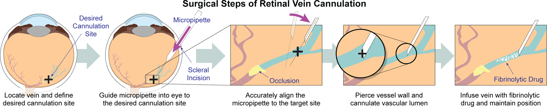
Shown is a schematic that highlights the critical steps of retinal vein cannulation from a surgical perspective.
To achieve these goals, the large positional error of the robotic system (340.6 μm) needed to be overcome to cannulate vein phantoms down to 120 μm in diameter. In light of this error, it was recognized that simply commanding the robot to pierce the vein phantom in a single motion would be insufficient to guarantee cannulation. However, the robot has incremental motion resolution of 1.25 μm for advancing the micropipette and 0.3 and 0.9 mdeg on the two rotational joints for controlling micropipette orientation. Coupled with OCT feedback, these motion resolutions could be sufficient for targeting the vein phantom and performing cannulation. Also, targeting the vein does not account for vein displacement during retina piercing, so a method to confirm a fluid connection between the micropipette and the vascular lumen would also be required. These cannulation requirements and the limitations of the robotic system led to the three-step approach developed in this work.
III. Experimental Setup
A. Intraocular Robotic Surgical System
The robotic system used in this work was the Intraocular Robotic Interventional Surgical System (IRISS). The IRISS has been used to perform teleoperated RVC, vitrectomy, and complete lens extractions on ex vivo pig eyes [17], [18]. In addition, the IRISS was used to demonstrate partially automated lens removal on ex vivo pig eyes with OCT feedback [19], [20]. This paper highlights work that performs automated cannulation on silicone retinal vein phantoms. Automated cannulation is a more challenging problem than that addressed in previous work for two reasons: (1) automation cannot rely on a human operator to sense and make decisions and (2) the accuracy requirements of RVC (on the order of micrometers) are more stringent than those of emulsified lens extraction (on the order of millimeters)
In the configuration used in this work, the IRISS is capable of controlling three degrees of freedom of a mounted surgical instrument. The first two joints, θ1 and θ2, are rotational; the third, d3, is the translational motion of the surgical instrument (Fig. 2(a)). Detailed description of the IRISS mechanism is provided in previous work [18], [21]. One improvement of the IRISS over previously reported versions was the replacement of the original rack-and-pinion mechanism with a piezoelectric linear actuator (LL06A0-101, MICROMO) for actuation of the d3 translation (positional resolution 1.25 μm).
Fig. 2.
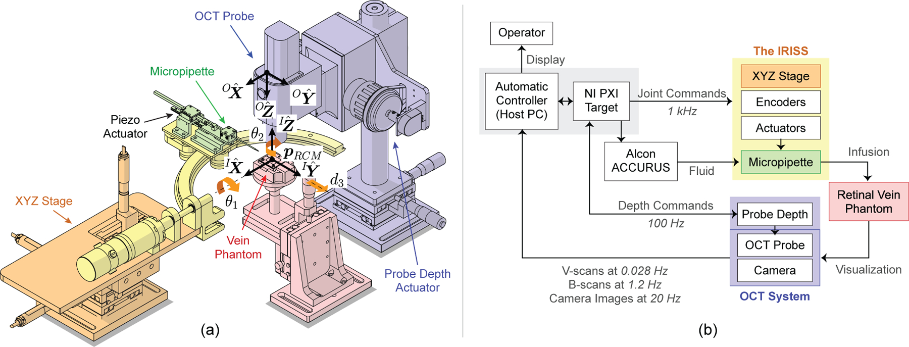
(a) Illustration of the OCT-integrated robotic system with coordinate frames and joint angles indicated. In this work, this system was used to demonstrate automated, image-guided retinal vein cannulation on silicone vein phantoms. (b) System-level diagram showing data and signal flow. The OCT and camera data are used as visual feedback in the automatic controller (host PC) to control the micropipette.
The mechanical design of the IRISS dictates the existence of a remote center of motion (RCM), or “pivot point,” such that—regardless of robot motion—the surgical instrument is constrained to pass through and rotate about the RCM. The three-dimensional translation of the RCM is actuated by an XYZ stage, allowing the RCM to be aligned to the scleral incision in the virtual eye model and to do so independently from the joint angles. The mathematical definition of the RCM, , is provided in detail in previous work [18], [22].
B. OCT System for Visual Feedback
The OCT system used in this work (Telesto II-1060LR, Thorlabs) is capable of acquiring two-dimensional cross-sectional images (B-scans) and three-dimensional volumetric images (C-scans). The OCT system also has a video camera that is calibrated with respect to the OCT probe. Despite the high resolution of the acquired data and the ability to image through the retinal phantom, the OCT system suffers from two main deficiencies: significant acquisition time (particularly for C-scans) and limited sensing depth (Table I).
TABLE I.
Relevant OCT and camera metrics
| Resolution [μm/px] | Acquisition Time [s] | Field of View [mm] | |
|---|---|---|---|
| B-scans | 9.18 (axial), 25 (lateral) | 0.089 | 10×9.4 |
| C-scans | 9.18 (axial), 25 (lateral) | 35.6 | 10×10×9.4 |
| Camera | 21.3 | 0.050 | 13.6×10.2 |
The significant acquisition time for a single C-scan (35.6 s) meant careful consideration had to be given to when C-scans were acquired in the procedure, using them only when the limited field of view of a B-scan would be insufficient. Therefore, C-scans were used only to obtain the three-dimensional model of the vein phantom (Section IV-B) and to localize the micropipette for the purpose of alignment (Appendix C). The lengthy acquisition time was a deficiency of the available OCT system and was addressed in the developed algorithm rather than through improvements to the OCT system itself.
C. System for Vein Infusion
As an alternative to a fibrinolytic drug, green-colored distilled water was used. The dyed water was deemed a satisfactory substitute for a commercially available fibrinolytic drug such as Ocriplasmin, which is 99.875% water and therefore expected to be similar in material and optical properties [23]. The delivery system for the dyed water was composed of a glass micropipette (Fig. 3) and a vitrectomy machine for generating the infusion pressure (ACCURUS 800CS, Alcon).
Fig. 3.
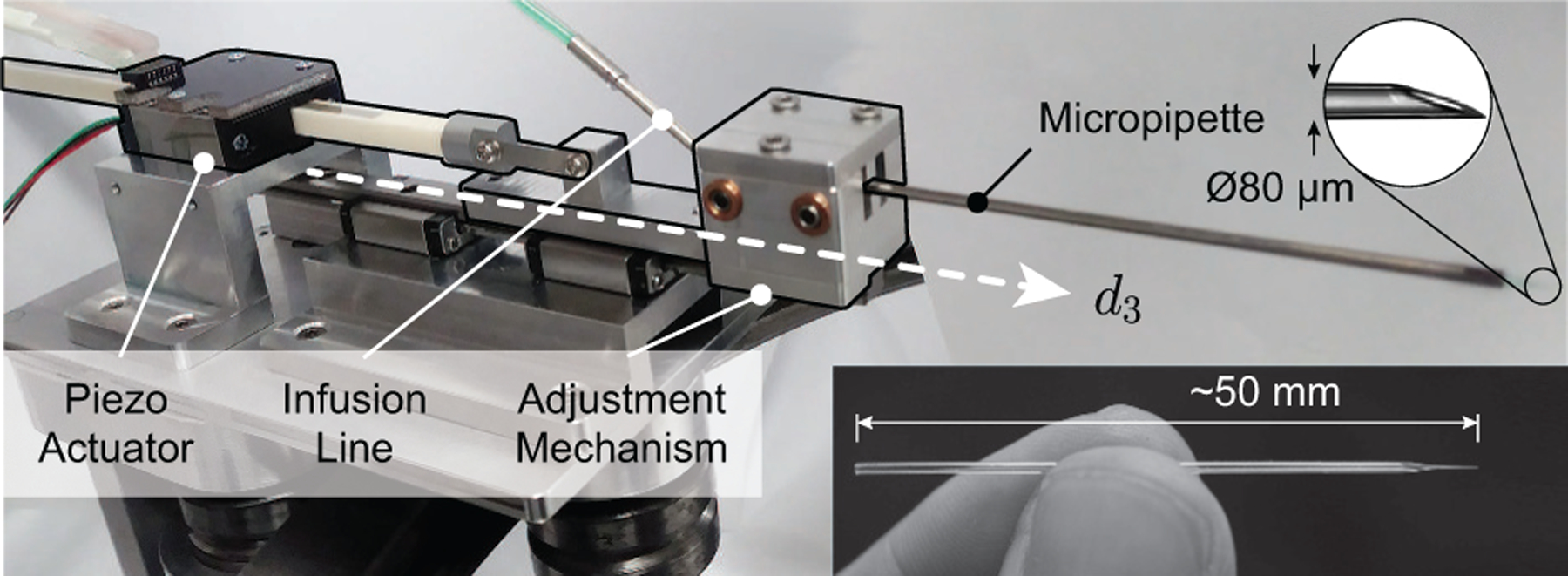
Photograph of piezo-actuated mechanism with mounted glass micropipette.
Because RVC is not currently performed in practice, no standard surgical instrument was commercially available. Both the Preceyes and the Belgium groups demonstrated the effectiveness of Ø30 μm glass micropipettes in in vivo pig eyes [11], [14]. However, both groups employed high-magnification, surgical-microscope visualization as feedback to the operating surgeon, whereas this work had to rely on a camera with much lower resolution alongside OCT which suffers from a low signal-to-noise ratio. Therefore, the chosen surgical instrument in this work was a glass micropipette with a slightly larger Ø80 μm tip (B100-58-80, Clunbury Scientific). The micropipette was epoxied to the inside of a stainless steel tube (316H17TW, MicroGroup) and connected to the viscous fluid control (VFC) line of the ACCURUS. The ACCURUS was reverse-engineered to ascertain the communication protocol with its foot pedal and this connection used to control its VFC output via the host computer, which in turn controlled the infusion pressure in the micropipette.
D. Retinal Vein Phantom
A silicone retinal vein phantom was developed for use as the eye model. No retinal vein phantom was commercially available at the time of writing. Phantoms developed by other research groups include partially incubated chicken embryos [24], pieces of human hair painted red [25], and various structures created with polydimethyl siloxane [26], [27]. However, all phantoms reported in the literature were deemed unsuitable due to inaccuracies in physical form (including vein shape and size) and lack of realism under OCT.
Instead, a silicone retinal vein phantom was developed as follows (Fig. 4). A stainless steel wire was inserted into a chambered mold and the mold filled with silicone. After curing, the wire was removed, leaving a void space (the vascular lumen). This void space was filled with red-colored distilled water to mimic blood. The syringe used to fill the vein was secured in place to provide a positive fluid pressure, analogous to positive blood pressure.
Fig. 4.
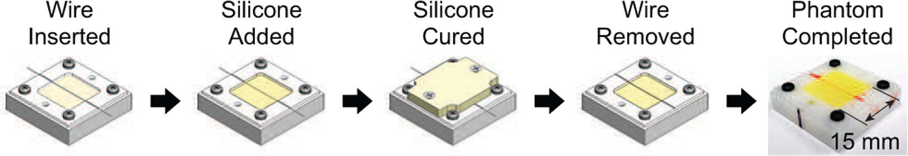
Illustration of the five-step process to create the retinal vein phantoms. Aside from an overnight cure time, the process was fast (approximately 10 minutes) and produced sufficiently realistic vein phantoms.
Three vein diameters were made: Ø120, Ø160, and Ø200 μm, representing the range of vessel diameters found near the lamina cribrosa [4], [5]. These vessels tend to exhibit larger radii of curvature, minimal branching, and reduced tortuosity, which were not considered important design factors. The physical and optical properties of the developed phantom were deemed sufficiently realistic for the purpose of evaluating the system’s sensing and guidance capabilities.
E. Host PC and GUI
The control software for the automated procedure was developed in National Instruments LabVIEW and run on a PXI real-time target at a control loop of 100 Hz (Figure 2(b)). A custom graphical user interface (GUI) was used as a display for the operator. To perform a trial, the system required two mouse clicks by the operator: one to initiate a new trial and a second to indicate a desired cannulation point.
IV. Technical Approach
Based on the requirements discussed in Section II, we segment vein cannulation and infusion into three steps:
Vein Approach: The operator defines a desired cannulation point, pc, and the micropipette is guided into the virtual eye to a point near the vein, just above the retina
Vein Targeting: The micropipette is aligned to the vein to within 20 μm
Vein Cannulation: The micropipette is inserted into the vein with camera feedback to confirm access and dyed water is infused into the vein for a fixed duration
These three steps are discussed in detail in this section.
A. Define Desired Cannulation Point
At the beginning of a trial, a camera image of the vein phantom was displayed to the operator, who selected a desired cannulation point (Fig. 5(a)). A bounded stack of B-scans was selected from an acquired C-scan centered at Cpc. For each of the B-scans (Fig. 5(b)), a region of interest (ROI) was defined in the vicinity of Cpc using the maximum expected width of the vein (200 μm) and the detected top and bottom surfaces of the phantom. The ROI was Gaussian blurred and the center of the minimum-intensity region detected (yellow “plus” in Fig. 5(d)). This point was considered the vascular lumen center for this B-scan and this process was repeated for all B-scans in the stack.
Fig. 5.
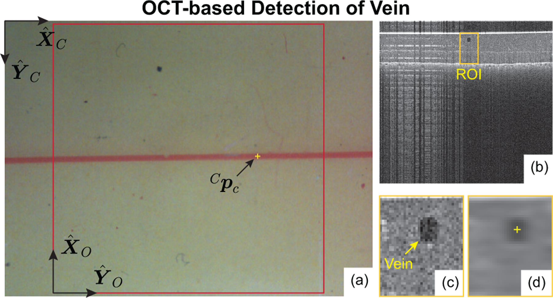
(a) Example camera image with operator-selected cannulation point, (b) B-scan cross-section of phantom, (c) region of interest (ROI), and (d) detected vein center (the output of the image-processing algorithm).
Due to low camera resolution (21.3 μm/px) and human error in clicking a computer mouse, it could not be assumed that the operator-selected point corresponds to a point actually inside the vein. Instead, Cpc was used to define a vertical line (normal to the phantom surface) and the true cannulation point, , was chosen as the closest lumen center point to this vertical line. Note: the cannulation point, pc, is critical in all subsequent steps.
B. Step A: Vein Approach
Under the assumption that the radius of curvature of the vein was large in the vicinity of pc, the detected center points were smoothed and the resulting curve was considered to be the vein model in the OCT frame (red line in Fig. 6). A virtual eye model was constructed around this model by defining a line from pc to the scleral incision, , at an angle of 60° from the retina surface (based on common surgical practice for retinal access) and with a length of 18.5 mm (based on average human anatomy). Throughout the procedure, the motion of the IRISS was constrained by this virtual eye model to obey access restrictions and pivot about the scleral incision.
Fig. 6.
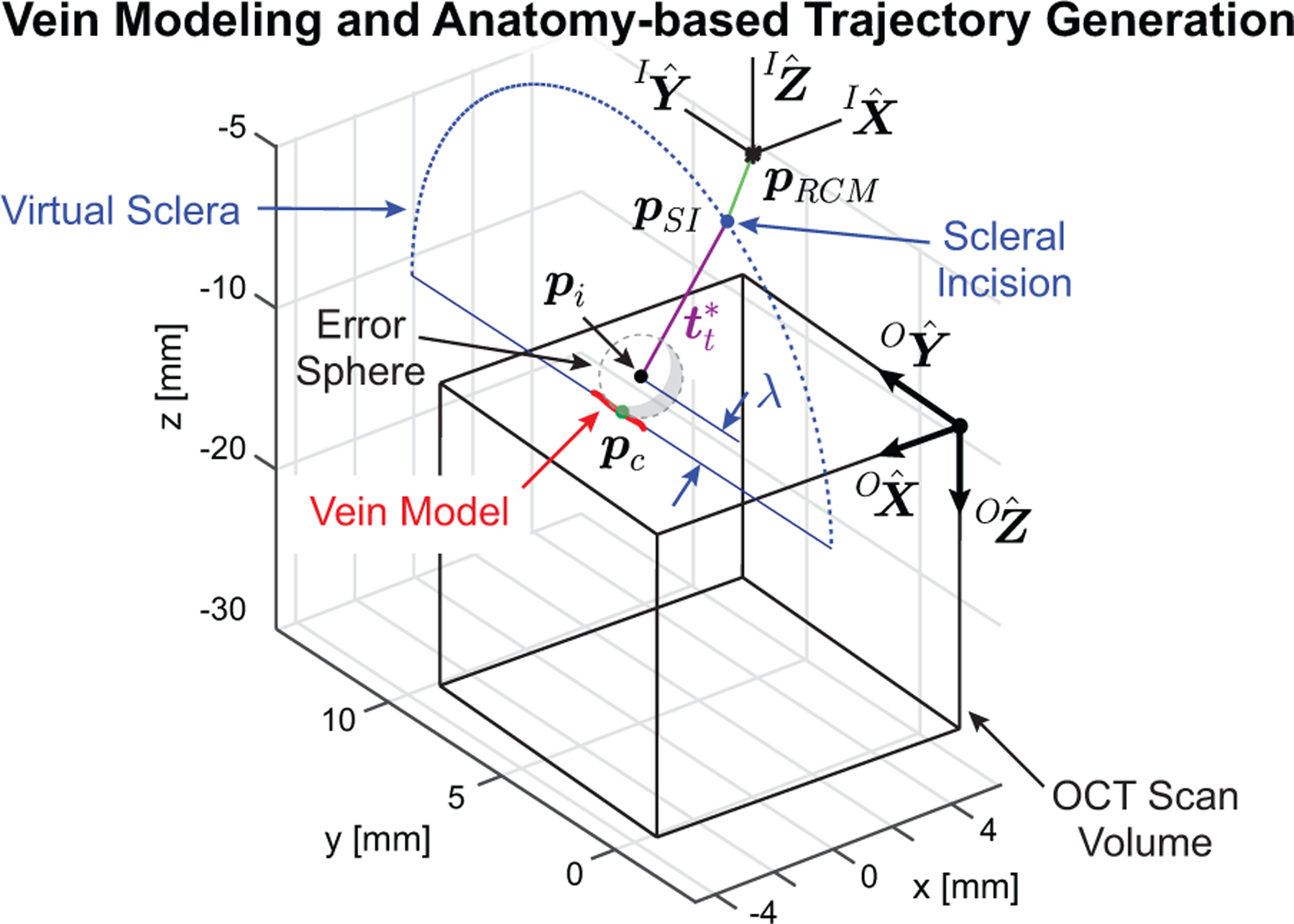
Generated vein model and with two-part trajectory for approaching the desired cannulation point.
From the virtual eye model, two trajectories were generated. The first was a joint-space trajectory for the XYZ stage to translate such that pRCM would become coincident with pSI (green line in Fig. 6). This aligns the robotic system to the virtual eye such that any subsequent motion is constrained to pass through pSI. The second is a joint-space trajectory in θ1, θ2, and d3 such that the micropipette tip, , moves towards a via point, , along an ideal insertion trajectory, , and concludes with pt located within an “error sphere” a distance λ from the surface. This trajectory is represented in Fig. 6 (violet line) and the details of calculating λ and defining the error sphere are provided in Appendix B.
With the trajectories determined, the system was commanded to first track the desired XYZ stage motion, then θ1 and θ2 were actuated to align the micropipette centerline to , and finally d3 was commanded forward such that pt passed through pSI and stopped when pt was within the error sphere. At the end of this step, the micropipette tip was guaranteed to be approximately 1 mm above the retinal phantom surface.
C. Step B: Vein Targeting
The goal of the Vein Targeting step was to accurately align the centerline of the micropipette such that it “pointed at” pc (Fig. 12). The micropipette centerline, , was defined as the unit vector from pRCM towards pt along the geometrical centerline of the micropipette. At the beginning of this step, the micropipette tip was somewhere in the vicinity of pc; at the end of this step, only forward motion of the micropipette was required to cannulate the vein (with all other joints held stationary), thereby reducing vein access to a single-DOF control problem during the Vein Cannulation step.
Fig. 12.
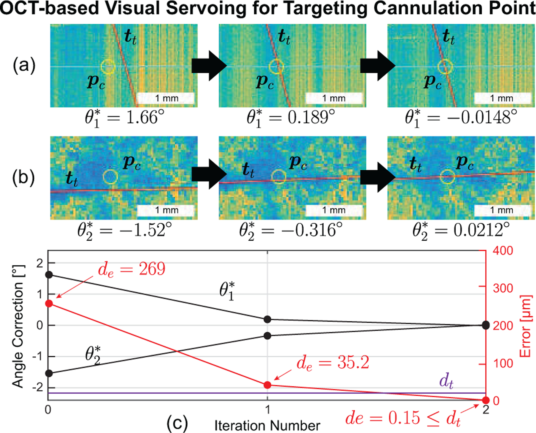
(a) Side view and (b) top view of OCT data demonstrating OCT-based visual servoing of the micropipette during the vein targeting step for the more common two-iteration case. (c) The calculated error shows a fast (two iteration) decrease to less than the error threshold (20 μm).
To accomplish this, a C-scan of the micropipette was acquired and processed to locate the centerline (Appendix C). Three errors were defined (Fig. 8): δθ1 is the angular displacement of from pRCM to pc in the plane, δθ2 is the angular displacement in the plane, and de is the perpendicular distance from to pc, calculated as
| (1) |
where is any point on and is a unit vector in the direction of . The goal of the Vein Targeting step was to minimize de by reducing the magnitude of δθ1 and δθ2. If de < dt, an error threshold, then the micropipette centerline was considered to accurately intersect pc and the algorithm was considered complete. From geometric considerations and surgical accuracy requirements dt = 20 μm.
Fig. 8.
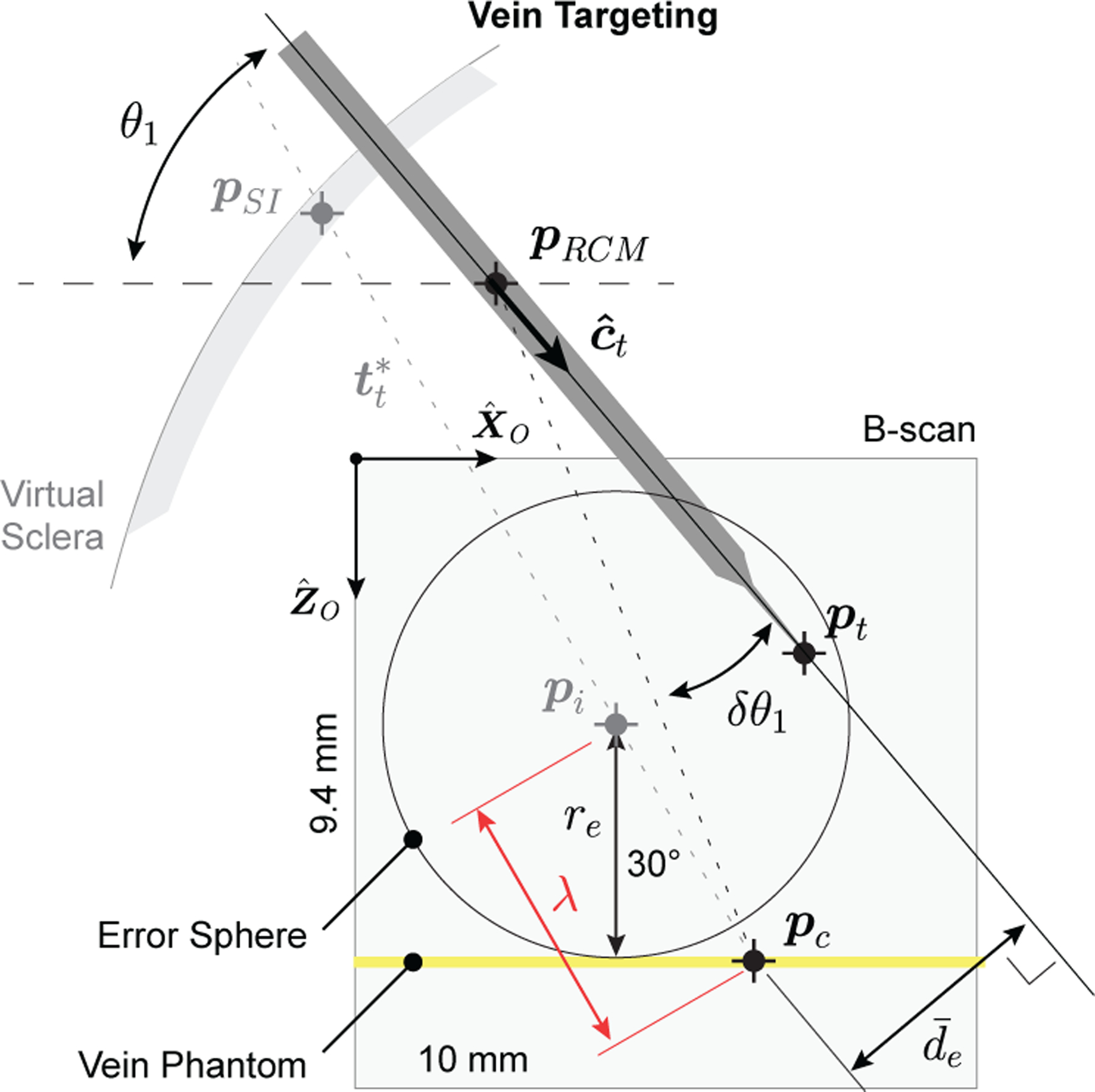
Illustration of mathematical definitions during the vein targeting step. Note: Relative dimensions are not to scale and represents the projection of de onto the plane.
The angular errors δθ1 and δθ2 were calculated from the angle between (1) the line from pRCM to pc and (2) the line from pRCM to pt. The projection of this angle in the plane was δθ1; its projection in the plane was δθ2. For the first iteration, the location of pRCM in the OCT frame was used; in subsequent iterations, pRCM was calculated using the current iteration’s detected centerline along with all previously detected centerlines [18], [22].
With the angular errors calculated, the robot was commanded to correct them. If de ≥ dt, then the algorithm repeated: a new C-scan was acquired, the micropipette centerlines detected, δθ1 and δθ2 determined, and the robot was commanded to move again. Once de < dt, the algorithm was considered complete and the micropipette centerline was assumed to point at pc to within 20 μm.
With the micropipette centerline known, its tip location, pt, was defined as the intersection of the centerline with a plane that passes through the tool tip. This plane was defined by binary classification of all B-scans in the most recent C-scan based on whether or not they contained micropipette data. The transition between B-scans with micropipette and those without was defined as a plane passing through pt. The distance from pt to the phantom surface was defined as dg (known to within 25 μm) and calculated based on the known location of the phantom surface previously determined as part of the vein-modeling step (Section IV-A).
D. Step C: Vein Cannulation
From initial calibration (Appendix A), the forward motion of the piezoelectric actuator was ensured to align with the micropipette centerline. Therefore, from ideal geometrical considerations, if the micropipette were to advanced the distance between pt and pc, pt would be at pc and infusion could be initiated. In reality, the vein phantom exhibits nonlinear elasticity and will dynamically deform under the force of the micropipette, shifting the vein away from the advancing micropipette. To address the physical compliance of the phantom and ensure vein access, two techniques were implemented: an automated motion to superficially split the phantom surface and an iterative forward-motion algorithm that checked for cannulation using camera feedback.
For the automated surface-splitting motion, the micropipette was commanded to touch the surface of the retinal phantom by moving forward dg, the distance from pt to the surface (Section IV-C). At this point, the micropipette was quickly advanced 30 μm and then immediately retracted 25 μm—an overall advancement of 5 μm. This technique was performed only once at the surface of the retinal phantom. It is theorized that the initial puncture creates a small rift in the surface of the phantom, allowing all subsequent forward motion to pass through the rift and eventually access the vascular lumen.
Following the automated surface-splitting motion, the micropipette was progressed in 5 μm increments towards pc. After each increment, the camera image was processed to detect color change in the glass micropipette tip (Fig. 9). The tip appeared green if outside the vein, but once cannulation1 occurred, the pressure difference between the blood analog inside the vein and the dyed water inside the micropipette caused back flow of blood analog into the tip, changing its color to red. A ROI around the micropipette tip was isolated in the camera image based on known geometry and the position of pc. The ROI was Gaussian blurred; masked to remove the background; converted to hue, saturation, value (HSV) color space; and averaged in hue to result in a mean value between 0 and 1. A mean value greater than 0.6 (bright intensity) was considered red (cannulated); a mean value less than or equal to 0.6 (dark intensity) was considered green (not cannulated).
Fig. 9.
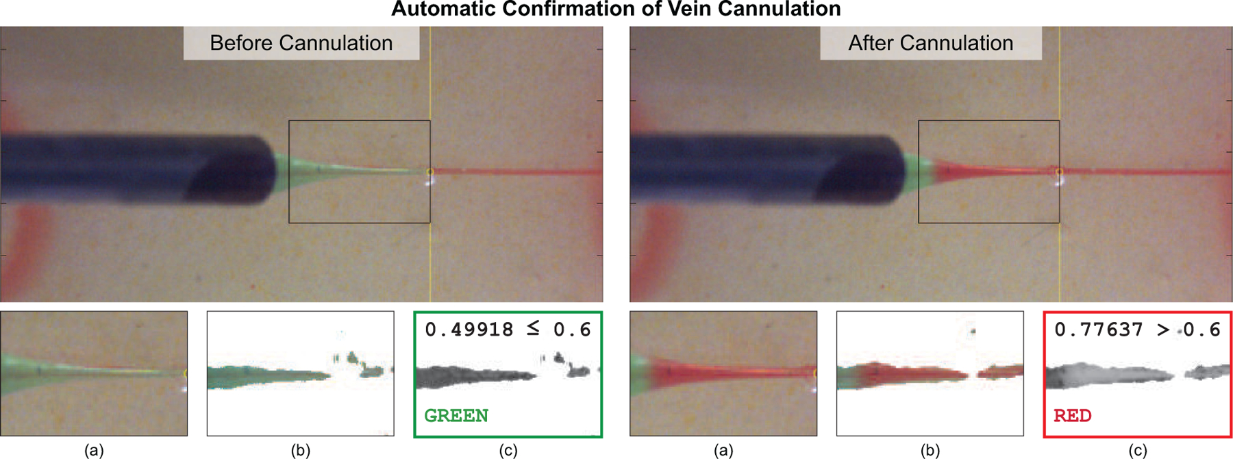
The system automatically confirmed vein cannulation by detecting a color change (green to red) in the glass micropipette after vein puncture. This color change was guaranteed upon successful cannulation due to the controlled pressure differential between the blood analog inside the vein phantom and the dyed water inside the micropipette. Important steps of the image-processing algorithm included (a) selecting an ROI, (b) blurring and masking, and (c) averaging hue values to determine color.
Once the system detected successful cannulation through the back flow, the d3 progression was stopped and infusion was initiated. Infusion pressure (10 mmHg) and duration (10 s) were both adjustable parameters. Upon completion of infusion, the system retracted the micropipette from the virtual eye and the automated RVC procedure was considered complete.
V. Experiment Design and Results
A. Experimental Design
An operator was tasked with performing n = 30 trials on phantoms with three distinct vein diameters: Ø120 μm, Ø160 μm, and Ø200 μm. The retinal vein phantoms were prepared and placed within the robotic workspace and within the scanning volume of the OCT. The operator then commanded the system to begin a trial and selected a desired cannulation point from the camera image. During all trials, the system recorded timestamps, joint angles, OCT probe position, XYZ stage position, camera images, and a variety of OCT data. For all trials, the infusion pressure was chosen as 10 mmHg and the infusion duration was set to 10 seconds for practical considerations. Success of infusion was defined as a red-to-green color change of the vein phantom.
Three failure cases were defined:
No Cannulation: No dyed water was infused
Reflux: Dyed water leaked onto the phantom surface
Subretinal Bleb Formation: Dyed water was injected beneath the phantom
In the case of “no cannulation,” the micropipette tip was embedded inside the phantom but missed the vein and therefore the low infusion pressure was insufficient to allow dyed water to flow. Reflux occurs when the micropipette tip was too shallow during infusion; subretinal bleb formation occurs when the micropipette tip was too deep. Illustrations of the three failure cases were manually produced via teleoperation of the robotic system (Fig. 10(c–e)). In surgical practice, reflux and subretinal injection during RVC would be considered unsatisfactory due to inefficacy: these results represent clear failures of the intended surgical procedure.
Fig. 10.
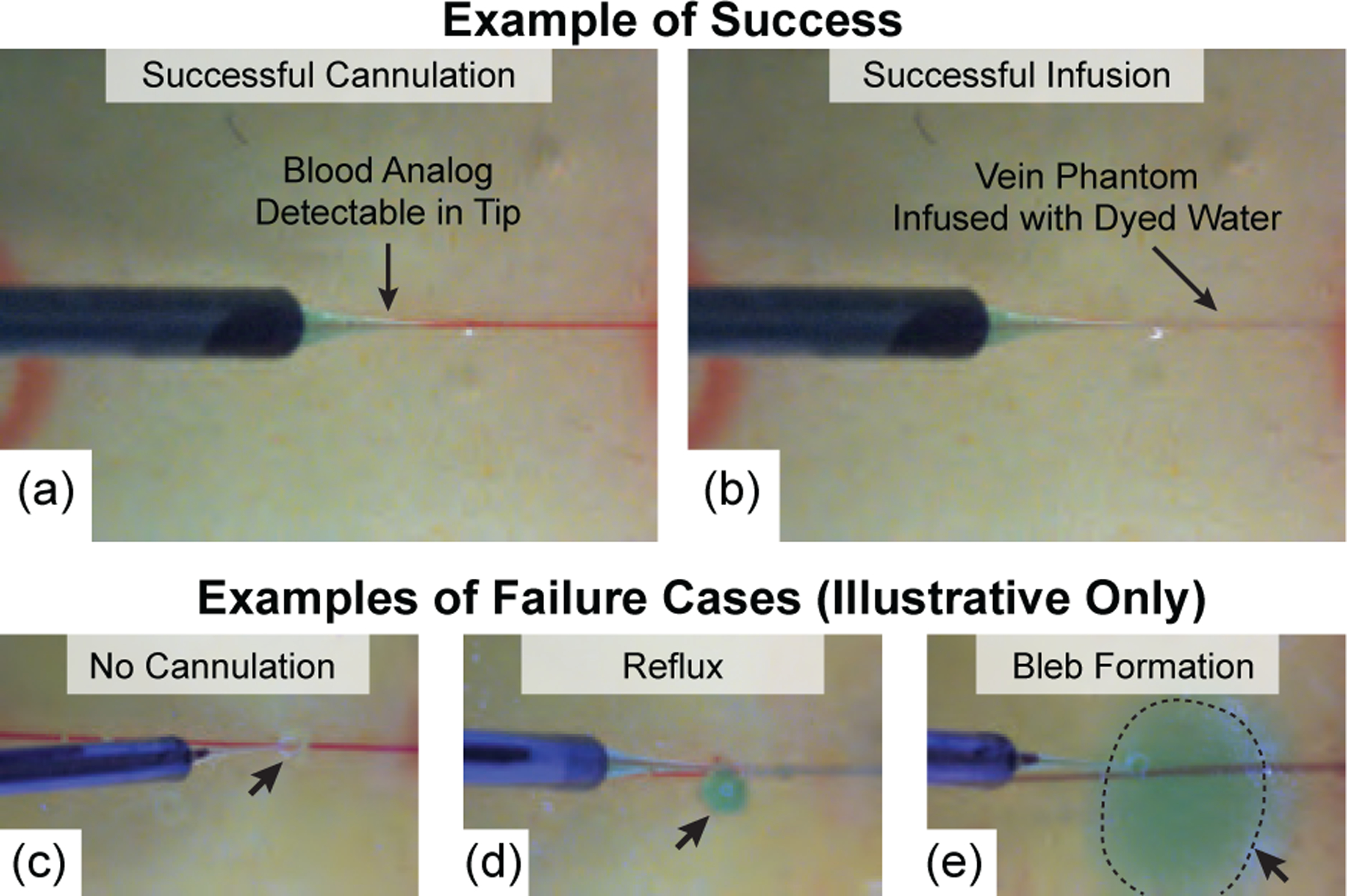
(a) Camera view following successful vein cannulation and (b) following successful infusion. For comparison purposes only, three failure cases were manually produced via teleoperation of the robotic system outside of the scope of the experimental trials: (c) no infusion due to failed cannulation, (d) reflux, and (e) subretinal bleb formation.
Differences in vein depth (measured from the phantom surface) were the result of the fabrication process and were intentionally perturbed during fabrication to produced a range of depths (Fig. 13). At the time of infusion, a B-scan of the micropipette during infusion was acquired (Fig. 15) and manually processed after the experiment to determine the final tip depth. Differences between vein depth and tip depth represent a measure of error and were used to assess the system’s ability to account for depth variation.
Fig. 13.
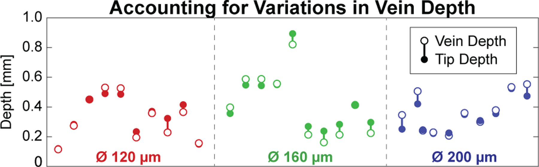
Fabrication differences between phantoms resulted in a variety of vein depths (open dots), but the system was able to target each (solid dots) with acceptable error (vertical bars).
B. Experimental Results
Out of n = 30 trials, all 30 were deemed successful: the system successfully cannulated the vein (Fig. 10(a)) and infused the dyed water into the lumen of the vein phantom (Fig. 10(b)). None of the 30 trials resulted in a failure case.
Total trial time from initial operator click to retraction of the micropipette was 4:52±0:28 (max: 6:03; min: 3:54). The time required for vein approach was 0:46±0:06 (max: 1:10; min: 0:40), for vein targeting was 2:19±0:27 (max: 3:14; min: 1:28), and for vein cannulation was 0:48±0:33 (max: 2:01; min: 0:13). The average trial time with breakdown is shown in Fig. 11. For the iterative Vein Targeting step, the majority (21 trials) required two iterations (Fig. 12), the remainder required only one iteration (5 trials) or three iterations (4 trials). The final cannulation angles across all trials were recorded as 59.88±0.18° (min.: 59.39°; max.: 60.15°).
Fig. 11.
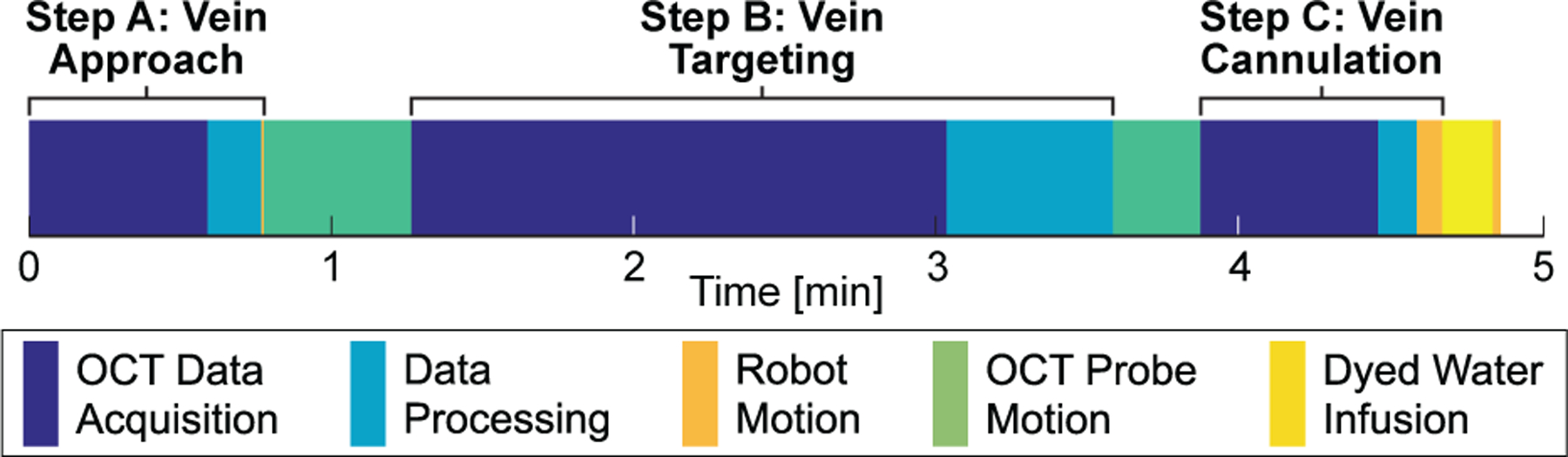
Average time requirements across all trials. The majority of time was spent acquiring OCT C-scans and translating the OCT probe.
Average vein depth was 356.2±168.9 (min: 88.7; max: 807.6) μm and the average difference from the final tool depth was 39.1±33.4 (min: 1.54; max: 105.6) μm across all trials (Fig. 13). During the Vein Cannulation step, the micropipette was incremented forward by 5 μm, the system paused for 200 ms, and then the camera image was acquired and processed to detect a color change (Fig. 7). From videos obtained during the experiments, it required approximately 2 s in all trials for the micropipette tip to fill with enough red fluid to be detectable by the camera, representing a maximum progression of 50 μm into the vein phantom following successful cannulation.
Fig. 7.
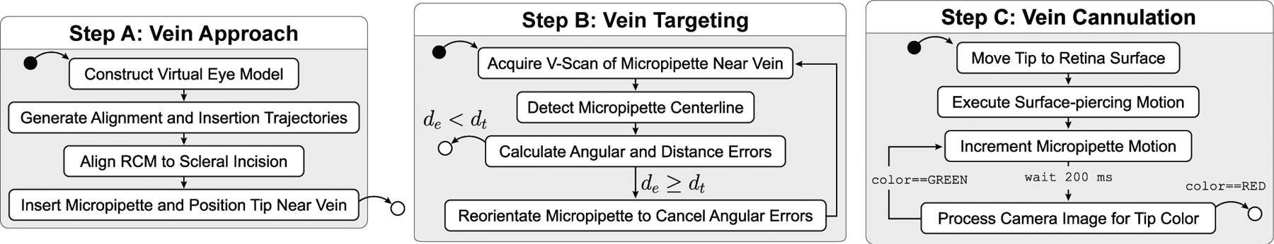
Schematic showing the three main steps of the procedure. Solid black dots represent start points; white dots represent end points. Variable definitions are provided in the text.
VI. Discussion
The main contribution of this work was the automation of a cannulation procedure that accurately targets a desired point to within 20 μm. The goal was to enable a robotic system to perform automated cannulation on retinal vein phantoms with consistent and deterministic results. It is noted that the IRISS was designed for a wide range of intraocular surgical procedures, and while there are similarities between the developed system and those employed elsewhere (e.g., in cell laboratories), the OCT-based method developed in this work specifically enhances the capabilities of the IRISS by overcoming the accuracy and precision limitations inherent to its range of versatility.
None of the trials resulted in unsuccessful cannulation, and it was necessary to intentionally force the system to miss the vein for the purpose of generating the failure cases shown in Fig. 10. The comparison of OCT-detected vein center vs. final micropipette tip depth during infusion (Fig. 13) also provided confidence that the system was able to consistently access the vein phantom despite variations in diameter and depth. Similarly, the claim that the robotic system was able to accurately target a point to within 20 μm was supported by this success, as the vein can only be infused when the micropipette tip had cannulated the vein phantom.
The system was shown to be capable of targeting retinal vein phantoms down to 120 μm and cannulating the vein phantom with confirmation of success. Methods were developed to identify a desired cannulation point to within 25 μm (Section IV-A), guide a micropipette to within 1 mm of the retinal phantom surface (Section IV-B), and align a micropipette to within 20 μm of the desired cannulation point (Section IV-C).
The 2 s required for the micropipette tip to change color allowed the micropipette to progress upwards of 50 μm into the vein phantom after cannulation had already been achieved. The additional “overshoot” was considered beneficial as it guaranteed the micropipette was inside the vein phantom and subsequent infusion would be successful. For the smallest diameter vein phantom (120 μm), the system would have at least 4 s to detect a color change and stop the progression of the micropipette—at least twice the 2 s that was required.
The smallest evaluated vein diameter was 120 μm with a micropipette diameter of 80 μm. In comparison, both the Preceyes [11] and the Belgium [14] groups demonstrated the effectiveness of Ø30 μm glass micropipettes in vein diameters down to 80 μm. The ratio of free space to tip diameter for other groups was 1.7:1 whereas in this work it was only 0.5:1, representing a more challenging targeting problem. In addition, these groups used human-controlled feedback guided by a stereo microscope. In comparison, the system presented here offers an automated process with visualization of the micropipette tip as it cannulates the vascular lumen and performs infusion (Appendix D).
The major limitation of the system was speed. While the developed method was slow (2:19±0:27) the main bottleneck was the OCT data acquisition rate and not the robotic manipulation. Therefore, with improvements to the sensing speed—for example, through the live volumetric visualization system from Duke University (approximately 400 times faster than the current system) [28]—the system could achieve the necessary loop rates for real-time application (at least 10 Hz), reducing the maximum vein targeting time from 140 s to within 1 s.
Other significant limitations involve the developed phantom and include its stationary nature, its deficiencies in optical realism beneath OCT, and it not being included in a small, ocular-like housing. Of these, the lack of vein motion is perhaps the most unrealistic aspect that must be addressed in future work. Two types of vein mobility are recognized: (1) ocular motion due to patient eye movement, breathing, and heartbeat, and (2) lateral and vertical vein deformation under the force of the micropipette during attempted cannulation. Other groups have demonstrated methods to account for ocular motion through, for example, the eye- or vein-tracking of lateral movements. In contrast, we developed a method to account for vertical vein deformation via detection of a visual change in the camera images. What remains is to account for the lateral mobility of the vein within the delicate retinal tissue, which requires the intended extension into more realistic biological models and would benefit from faster OCT acquisition. Specifically, the Vein Targeting step can theoretically account for all types of vein mobility without significant modification to the algorithm, provided the latency of OCT-image acquisition and processing can be reduced to enable continuous real-time feedback.
To confirm cannulation, a reliable method to detect connection of the fluid channels between the micropipette and lumen was required. Even though the OCT data provided depth information and higher resolution, this information was considered less reliable because, for example, the micropipette could be occluded during the puncture of the lumen and remain undetected by the OCT. Alternatively, it was recognized that pressure change (e.g., as done in [16]) was a viable alternative. In this paper, the pressure difference was detectable by the camera through color change, but other contrasting agents for the camera or the OCT may be used.
Even though the B-scans acquired from automatic tracking of the micropipette (Appendix D) were not used to guide the robot to perform cannulation or infusion, this ability is expected to be useful in future applications. For example, it is conceivable that automated segmentation of the OCT visualization could be employed to detect vein compression, movement of the surrounding anatomy, and double puncturing of the vessel. By using this information as feedback to guide its reactions, the current system could be enhanced to automatically account for a wider range of target motion.
To prepare the system for surgical trials, the total time must be reduced and vein motion must be accounted for. Of the three steps, Vein Targeting has the most room for improvement, as discussed. In addition, to both compensate for vein motion and reduce total time, the computer-vision algorithms can be extended from segmentation and localization to tracking visual features specific to the in vivo eye. This involves adopting existing segmentation algorithms to localize vessel locations within the OCT frame (e.g., [29]) and identifying a detectable visual change indicative of successful cannulation. Finally, to develop a safe and robust clinical workflow with the robotic automation’s precision and accuracy, it may be beneficial to provide the operator more control than the two discrete decision points presented in this paper. The operator should be given control of scaling the speed of the instrument movement, including pausing at zero speed and increasing to faster-than-normal speed to increase efficiency.
VII. Conclusions and Future Work
This work presented an intraocular robotic system capable of performing automated cannulation on silicone retinal vein phantoms. The developed system reduces the cannulation of a vein phantom to a pair of waypoints where the workflow is only advanced upon a discrete logical decision by the operator. Automated steps included (1) guidance of the micropipette to a near-vein position, (2) accurate alignment of the micropipette to the target cannulation point, and (3) vein access by using OCT and camera feedback. The developed system was evaluated through 30 trials and shown to be capable of cannulating and infusing the vein phantoms with no cases of failure.
It is expected that the developed technology may some day facilitate the treatment of retinal vein occlusion by replacing the surgeon’s limitations in sensing and micropipette control with finer-resolution sensing and more precise motion. While there is room for improvement in the design of the vein phantom, future work will focus on applying the automated aspects of this work on biological models. To this end, the following mitigation steps are envisioned to address the foreseen challenges.
First, an automated procedure for tracking the vein in the presence of retinal movement must be developed to account for eye movement during the vein targeting and cannulation step. Unless an OCT system with a faster C-scan acquisition time can be found, the system will need to abandon its reliance on the time-consuming C-scans in favor of an algorithm that offers the same degree of accuracy using only the much faster B-scans to localize the micropipette and align itself to the vessel. Second, the deformation and mobility of the retinal vessel due to the force of the micropipette must be accounted for in all directions, suggesting a system which can sense and account for this motion or a technique that physically constrains the vessel to facilitate cannulation. Finally, the OCT feedback during cannulation (Fig. 16) can offer a novel means of ascertaining micropipette tip location relative to the vascular lumen, and this possibility remains to be explored.
Biographies

Matthew J. Gerber received the B.S. and M.S. degrees in Mechanical Engineering from The Ohio State University, Columbus, Ohio in 2013 and 2014, and the Ph.D. degree in Mechanical Engineering from the University of California, Los Angeles in 2019. In 2020, he joined the Stein Eye Institute in the Department of Ophthalmology at the University of California, Los Angeles where he currently works as a Postdoctoral Scholar. His research interests include surgical robotics and computer vision.

Jean-Pierre Hubschman trained in Ophthalmology at the Hôpital de la Timone in Marseille, France from 1991 to 1996 and received his M.D. degree from Aix-Marseille University in 1996. He did a fellowship in vitreoretinal surgery from 1996 to 1998 and then headed the Retina department of the Ophthalmologic Center of Saint Jean de Luz (France), the Polyclinique Aguilera Biarritz (France), and the Policlínica Gipuzkoa, San Sebastıian (Spain). In 2007, Jean-Pierre Hubschman joined the Retina division of the Stein Eye Institute at UCLA as an Assistant Professor of Ophthalmology.

Tsu-Chin Tsao received the B.S. degree in engineering from the National Taiwan University, Taipei, Taiwan, in 1981, and the M.S. and Ph.D. degrees in mechanical engineering from the University of California, Berkeley, in 1984 and 1988, respectively. In 1988, he joined the Department of Mechanical and Industrial Engineering at the University of Illinois at Urbana-Champaign, where he was an Assistant Professor and then an Associate Professor until July 1999. Subsequently, he joined the faculty of Mechanical and Aerospace Engineering Department, UCLA where he is currently a Professor.
Appendix A. Micropipette Calibration
The micropipette was mounted to a custom adjustment mechanism that included three hex adjusters with 200 μm pitch (F3ES8, ThorLabs). To guarantee that forward motion of the piezoelectric actuator would result in sufficiently small (<5 μm) parasitic lateral error in forward motion of the micropipette, it was necessary to ensure that the angular mounting errors of the micropipette were constrained to be less than 0.15° (from geometric considerations).
To ensure the angular error was within this bound, an iterative process was developed based on OCT-based characterization of the micropipette centerline. The micropipette was moved to 15 values of θ1 from −10° to 60° and 17 values of θ2 from −40° to 40°. At each pose, a C-scan was acquired, the micropipette centerline found [19], and the angular errors calculated. For adjusting θ1, the physical height of the micropipette from the circular track was increased by adding shim stock beneath the adjustment mechanism. For adjusting θ2, the hex adjusters were turned according to the known screw pitch. Once complete, the process was repeated: the micropipette was commanded to move to the aforementioned poses, C-scans were acquired, and the angular errors were calculated. Once the angular error in both θ1 and θ2 were less than 0.15°, the process was considered complete. This alignment process required approximately two hours to perform but only needed to be performed once.
The accurate forward motion of the micropipette was verified using an experimental setup consisting of an inspection touch probe (resolution 1 μm) mounted with its spherical tip in physical contact with the side of the micropipette. The touch probe measurement was recorded, the micropipette was commanded forward 2 mm, and a second reading was obtained from the touch probe. The difference in measurements was the parasitic lateral error associated with forward motion of the micropipette and was calculated as 2.73±1.33 (min.: 0.067; max.: 4.96) μm (n = 50).
Appendix B. Error Sphere Definition and Calculation of λ
From purely geometric considerations, a line connecting pSI to pc would represent the ideal insertion trajectory into the eye to the vein. However, in the presence of robotic uncertainties, it would be imprudent to simply command the robotic joints to follow this line to pc. Instead, a via point, was defined along the ideal-insertion line a distance λ from pc (Fig. 8). If λ was defined to be greater than the maximum expected error of the motion, then the micropipette would be guaranteed to complete its approach to the vein without colliding with the phantom surface.
To determine λ, an “error sphere” was defined with its center coincident with pi and its surface tangent to the phantom surface. The radius of this sphere, re, was calculated as the sum of the maximum measured errors of registration and robotic motion. Therefore, λ can be calculated as
| (2) |
Fig. 14.
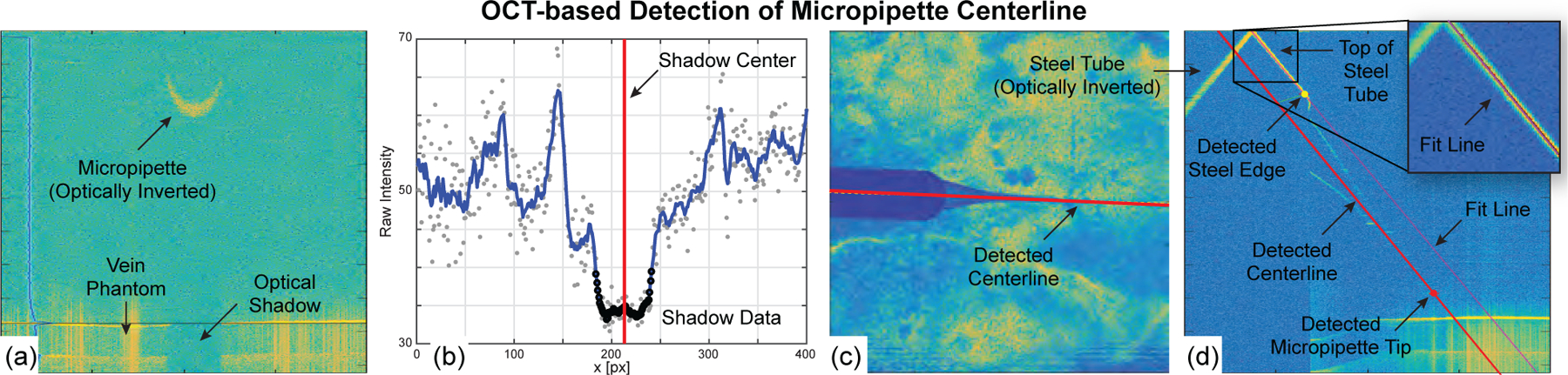
(a & b) B-scan data evaluated to detect the optical shadow cast by the micropipette, (c) detected micropipette centerline in the top view, and (d) detected steel edge, micropipette tip, and micropipette centerline in the side view.
The magnitude of error depends on initial calibration and other factors but can be measured according to the process described in previous work [19]. For the trials reported here, the registration error was measured as 190.0±77.1 μm with a maximum error of 340.6 μm. The maximum error (340.6 μm) was very large compared to the smallest targeted vein diameter (120 μm), justifying the attention given to this problem. For this study, re = 340.6 μm and therefore λ ≥ 393.3 μm.
Appendix C. Detection of Micropipette Centerline
The Vein Targeting step (Section IV-C) required knowledge of the micropipette centerline location, obtained by image-processing a C-scan as follows. The steel tube of the micropipette casts an optical shadow onto the retinal vein phantom in the acquired C-scans because OCT laser cannot penetrate steel (Fig. 14(a)). This shadow is easy to detect and invariant to micropipette orientation. In each B-scan, the retinal vein phantom surface was detected by averaging the horizontal intensity values, detecting the two largest peaks, and defining the peak with the smaller depth as the phantom surface. An ROI was defined based on known geometry, vertically blurred, and averaged along (Fig. 14(b)). The global minimum was detected and gradients of the blurred data were searched for the nearest, largest values on either side of the global minimum. These gradients corresponded to the edges of the shadow and their average corresponded to the shadow center (red line in Fig. 14(b)). In each B-scan, two values were obtained: the B-scan slice number, , and the shadow center, . After examining all B-scans in the C-scan, the points (, ) were fit with a line—this was the micropipette centerline projected into the top view (Fig. 14(c)).
From the C-scan data, a custom B-scan was compiled perpendicular to the plane and collinear with (Fig. 14(d)). By design, the steel tube was visible in the data and presented easily detectable features to use in ascertaining the micropipette centerline and tip locations. During the calibration of the micropipette, a side-view B-scan of the micropipette was acquired and the fixed distances between the steel edge to the micropipette tip and the top line of the steel tube to the micropipette centerline were manually measured. During the automated detection, the top of the steel tube was detected, a line was fit, and the edge of the steel tube was found. From these detected landmarks, the location of the micropipette centerline and tip could be known. The previously determined (, ) values were augmented with to form , using as the common values between the two views (top view and the side view). Image processing of a single C-scan to localize the micropipette centerline required approximately 10 s to complete and 1–2 mm of the micropipette to be visible.
Appendix D. Augmented OCT Feedback
Outside the scope of the automated procedures, augmented OCT B-scans where shown to the operator at a rate of 5 Hz during the cannulation procedure (Fig. 15). This feature provided additional visual feedback to the operator: the micropipette tip was overlaid by a visual marker when hidden inside the phantom. Furthermore, the B-scans automatically tracked the micropipette tip such that, in the event of movement (θ1, θ2, or d3), the OCT scanning plane rotated and/or translated to maintain a clear view of the micropipette. It was also possible to visualize the progression of dyed water inside the vein during infusion (Fig. 15(b)), thereby providing additional feedback to the operator that cannulation was successful and that infusion was progressing.
Fig. 15.
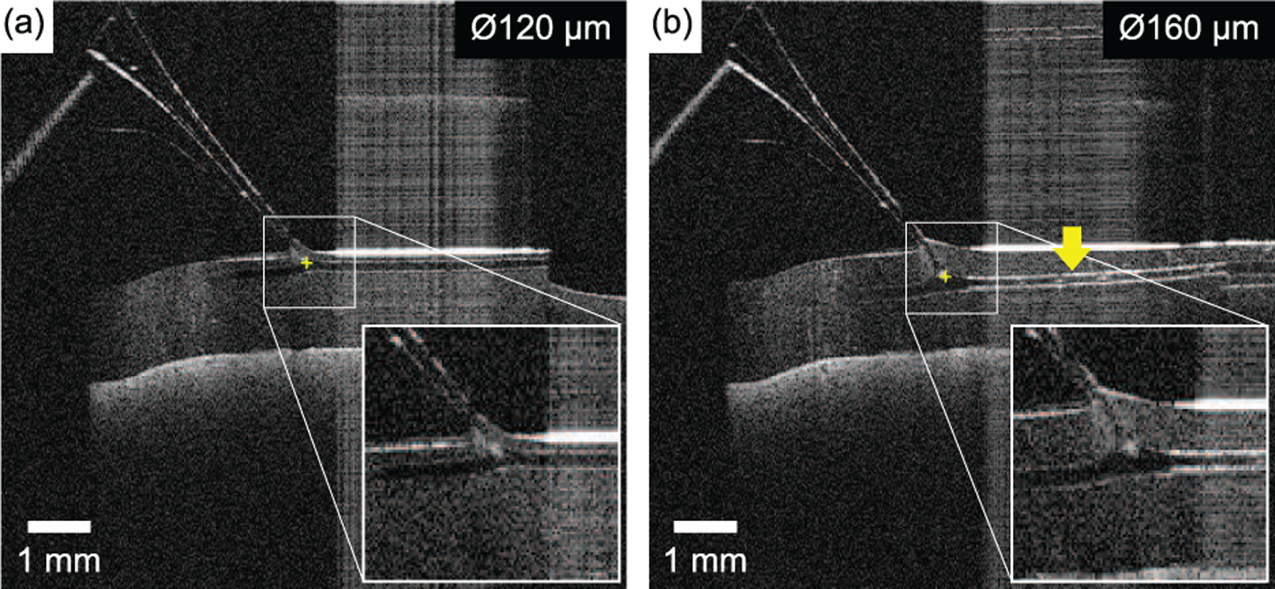
Two examples of the OCT feedback provided to the operator at a rate of 5 Hz during automated retinal vein cannulation of (a) a Ø120 μm vein and (b) a Ø160 μm vein. The tip of the micropipette (yellow “plus” symbol) was automatically overlaid atop the data and followed the tip as it cannulated the vein. In (b), the example shown was acquired within 1 s of infusion and shows the dyed water (yellow arrow) being infused through the vein phantom.
Appendix E. Acknowledgments
This work was supported in part by funds from the UCLA Stein Eye Institute; The Hess Foundation, New York, NY, USA; The Earl and Doris Peterson Fund, Los Angeles, CA, USA; an unrestricted institutional grant from Research to Prevent Blindness (RPB), NewYork, NY, USA; unrestricted gifts that support Tsao’s research program from various donors; the National Institutes of Health Grant No. R01-EY029689-01; and the Public Health Services Grant No. T32-EY7026-43. The authors would like to thank Ismael Chehaibou for his¨ surgical insight and expertise.
Footnotes
Due to the size and shape of the micropipette relative to the size of the lumen, the cannula (barrel) portion of the micropipette was not fully contained within the lumen and therefore was not strictly “cannulation” in the general clinical sense. Despite this, the single-wall puncture of the vein is referred throughout this paper as “cannulation” for linguistic convenience and to be consistent with the commonly used term “retinal vein cannulation.”
Contributor Information
Matthew J. Gerber, Mechanical and Aerospace Engineering Department, University of California, Los Angeles, CA, 90095 USA;
Jean-Pierre Hubschman, Stein Eye Institute, UCLA..
Tsu-Chin Tsao, Mechanical and Aerospace Engineering Department, University of California, Los Angeles, CA, 90095 USA;.
References
- [1].Rogers S et al. , “The prevalence of retinal vein occlusion: pooled data from population studies from the united states, europe, asia, and australia,” Ophthalmology, vol. 117, no. 2, pp. 313–319, 2010. [DOI] [PMC free article] [PubMed] [Google Scholar]
- [2].Laouri M et al. , “The burden of disease of retinal vein occlusion: review of the literature,” Eye, vol. 25, no. 8, p. 981, 2011. [DOI] [PMC free article] [PubMed] [Google Scholar]
- [3].Weiss JN, “Retinal surgery for treatment of central retinal vein occlusion,” Ophthalmic Surgery, Lasers and Imaging Retina, vol. 31, no. 2, pp. 162–165, 2000. [PubMed] [Google Scholar]
- [4].Ouyang Y et al. , “Retinal vessel diameter measurements by spectral domain optical coherence tomography,” Graefe’s Archive for Clinical and Experimental Ophthalmology, vol. 253, no. 4, pp. 499–509, 2015. [DOI] [PubMed] [Google Scholar]
- [5].Wong TY et al. , “Retinal vascular caliber, cardiovascular risk factors, and inflammation: the multi-ethnic study of atherosclerosis (mesa),” Investigative ophthalmology & visual science, vol. 47, no. 6, pp. 2341–2350, 2006. [DOI] [PMC free article] [PubMed] [Google Scholar]
- [6].Riviere CN et al. , “Characteristics of hand motion of eye surgeons,” in Proceedings of the 19th Annual International Conference of the IEEE Engineering in Medicine and Biology Society.’Magnificent Milestones and Emerging Opportunities in Medical Engineering’(Cat. No. 97CH36136), vol. 4. IEEE, 1997, pp. 1690–1693. [Google Scholar]
- [7].Harwell RC and Ferguson RL, “Physiologic tremor and microsurgery,” Microsurgery, vol. 4, no. 3, pp. 187–192, 1983. [DOI] [PubMed] [Google Scholar]
- [8].Hibbard PB et al. , “Magnitude, precision, and realism of depth perception in stereoscopic vision,” Cognitive Research: Principles and Implications, vol. 2, no. 1, p. 25, 2017. [DOI] [PMC free article] [PubMed] [Google Scholar]
- [9].de Smet MD et al. , “Human/robotic interaction: vision limits performance in simulated vitreoretinal surgery,” Acta ophthalmologica, vol. 97, no. 7, pp. 672–678, 2019. [DOI] [PubMed] [Google Scholar]
- [10].Gonenc B, Chae J, Gehlbach P, Taylor RH, and Iordachita I, “Towards robot-assisted retinal vein cannulation: A motorized force-sensing microneedle integrated with a handheld micromanipulator,” Sensors, vol. 17, no. 10, p. 2195, 2017. [DOI] [PMC free article] [PubMed] [Google Scholar]
- [11].de Smet MD et al. , “Robotic assisted cannulation of occluded retinal veins,” PloS one, vol. 11, no. 9, p. e0162037, 2016. [DOI] [PMC free article] [PubMed] [Google Scholar]
- [12].——, “Release of experimental retinal vein occlusions by direct intraluminal injection of ocriplasmin,” British Journal of Ophthalmology, vol. 100, no. 12, pp. 1742–1746, 2016. [DOI] [PMC free article] [PubMed] [Google Scholar]
- [13].Willekens K et al. , “Robot-assisted retinal vein cannulation in an in vivo porcine retinal vein occlusion model,” Acta ophthalmologica, vol. 95, no. 3, pp. 270–275, 2017. [DOI] [PubMed] [Google Scholar]
- [14].Gijbels A et al. , “In-human robot-assisted retinal vein cannulation, a world first,” Annals of biomedical engineering, vol. 46, no. 10, pp. 1676–1685, 2018. [DOI] [PubMed] [Google Scholar]
- [15].Chen AI et al. , “Deep learning robotic guidance for autonomous vascular access,” Nature Machine Intelligence, vol. 2, no. 2, pp. 104–115, 2020. [Google Scholar]
- [16].Chang Y-C et al. , “An automated mouse tail vascular access system by vision and pressure feedback,” IEEE/ASME Transactions on Mechatronics, vol. 20, no. 4, pp. 1616–1623, 2014. [DOI] [PMC free article] [PubMed] [Google Scholar]
- [17].Rahimy E et al. , “Robot-assisted intraocular surgery: development of the iriss and feasibility studies in an animal model,” Eye, vol. 27, no. 8, p. 972, 2013. [DOI] [PMC free article] [PubMed] [Google Scholar]
- [18].Wilson JT et al. , “Intraocular robotic interventional surgical system (iriss): Mechanical design, evaluation, and master–slave manipulation,” The International Journal of Medical Robotics and Computer Assisted Surgery, vol. 14, no. 1, p. e1842, 2018. [DOI] [PubMed] [Google Scholar]
- [19].Chen C-W et al. , “Intraocular robotic interventional surgical system (iriss): Semi-automated oct-guided cataract removal,” The International Journal of Medical Robotics and Computer Assisted Surgery, vol. 14, no. 6, p. e1949, 2018. [DOI] [PubMed] [Google Scholar]
- [20].——, “Semiautomated optical coherence tomography-guided robotic surgery for porcine lens removal,” Journal of Cataract and Refractive Surgery, vol. 45, no. 11, pp. 1665–1669, 2019. [DOI] [PMC free article] [PubMed] [Google Scholar]
- [21].Gerber MJ, “Optical coherence tomography–guided robotic system for automated retinal microsurgery,” Ph.D. dissertation, UCLA, 2019. [DOI] [PMC free article] [PubMed] [Google Scholar]
- [22].Wilson JT et al. , “Evaluating remote centers of motion for minimally invasive surgical robots by computer vision,” in 2010 IEEE/ASME International Conference on Advanced Intelligent Mechatronics. IEEE, 2010, pp. 1413–1418. [Google Scholar]
- [23].A. C. Inc., JETREA, ocriplasmin solution for intravitreal injection, ser. Interdisciplinary Applied Mathematics. ALCON Canada Inc., 2017. [Google Scholar]
- [24].Gonenc B et al. , “Evaluation of a force-sensing handheld robot for assisted retinal vein cannulation,” in 2018 40th Annual International Conference of the IEEE Engineering in Medicine and Biology Society (EMBC). IEEE, 2018, pp. 1–5. [DOI] [PMC free article] [PubMed] [Google Scholar]
- [25].MacLachlan RA et al. , “Micron: an actively stabilized handheld tool for microsurgery,” IEEE Transactions on Robotics, vol. 28, no. 1, pp. 195–212, 2011. [DOI] [PMC free article] [PubMed] [Google Scholar]
- [26].Nakano T et al. , “Multiscale fabrication of a transparent circulation type blood vessel simulator,” Biomicrofluidics, vol. 4, no. 4, p. 046505, 2010. [DOI] [PMC free article] [PubMed] [Google Scholar]
- [27].Tanaka S et al. , “Quantitative assessment of manual and robotic microcannulation for eye surgery using new eye model,” The International Journal of Medical Robotics and Computer Assisted Surgery, vol. 11, no. 2, pp. 210–217, 2015. [DOI] [PubMed] [Google Scholar]
- [28].Carrasco-Zevallos O et al. , “Live volumetric (4d) visualization and guidance of in vivo human ophthalmic surgery with intraoperative optical coherence tomography,” Scientific reports, vol. 6, p. 31689, 2016. [DOI] [PMC free article] [PubMed] [Google Scholar]
- [29].Pilch M, Wenner Y, Strohmayr E, Preising M, Friedburg C, zu Bexten EM, Lorenz B, and Stieger K, “Automated segmentation of retinal blood vessels in spectral domain optical coherence tomography scans,” Biomedical optics express, vol. 3, no. 7, pp. 1478–1491, 2012. [DOI] [PMC free article] [PubMed] [Google Scholar]