Abstract
In this study, the effect of organic substances on the fouling behavior of a thin film composite (TFC) membrane with in situ Ca2+ addition (TFC-Ca membrane) was evaluated. Bovine serum albumin (BSA), humic acid (HA) and sodium alginate (SA) were used as surrogate foulants for protein, natural organic substances and polysaccharides, respectively, thus enabling the analysis of foulant–membrane interaction in the membrane fouling process. Fouling experiments were carried out and the fouling mechanism was investigated by extended Derjaguin–Landau–Verwey–Overbeek (XDLVO) theory. SEM-EDX, ICP-OES and TOC analysis were applied to characterize the fouled TFC-Ca membrane. Results suggested that the interfacial free energies obtained from advanced contact angle measurements were correlated strongly with the rates of membrane fouling. In situ Ca2+ addition in the TFC membrane resulted in the decrease of the interfacial adhesion free energy (i.e., foulant–membrane interaction) and thus the mitigation of membrane fouling. The permeate flux of TFC-Ca FO membrane after organic fouling could be fully restored by simple physical cleaning. The antifouling mechanism of Ca2+ pre-binding carboxyl groups in the TFC-Ca FO membrane was demonstrated, which provides new insights into the development of antifouling TFC membranes in the future.
In this study, the effect of organic substances on the fouling behavior of a thin film composite (TFC) membrane with in situ Ca2+ addition (TFC-Ca membrane) was evaluated.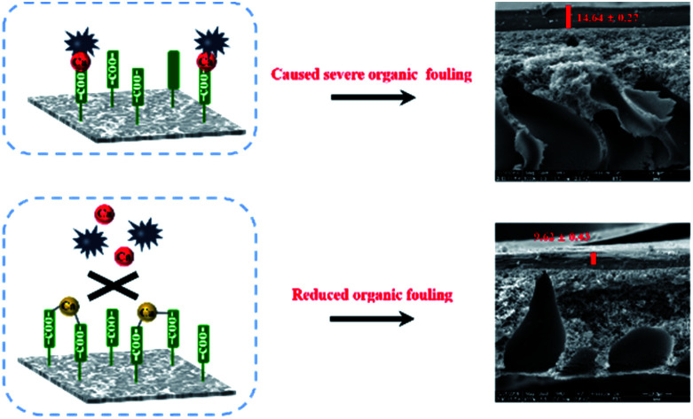
1. Introduction
Forward osmosis (FO) utilizes osmotic pressure as the driving force for water permeation through a semi-permeable membrane, and has been evaluated as a potential technology for water treatment and reclamation and attracted extensive attention in recent years.1–4 FO does not require hydraulic pressure for its operation, which may result in lower membrane fouling propensity than pressure-driven membrane processes.5–7 Thin-film composite (TFC) membranes have been widely used in FO due to their superior water permeability and selectivity.8,9 However, surface roughness, hydrophobicity and abundant functional groups of the TFC FO membranes inarguably make them highly susceptible to fouling.10–16 In particular, the extensive presence of carboxyl groups in the TFC FO membrane surfaces are more prone to organic fouling, because divalent ions such as Ca2+ ions in the feed solution can bind to carboxyl groups on the membrane surface and those of the organic foulants, resulting in the severe organic fouling.17 The adsorption and accumulation of various organic substances on the membrane surface increase the hydraulic resistance across the membrane and reduce the treatment efficiency.
For these reasons, significant efforts have been made over the past years to improve the fouling resistance of TFC FO membranes by tailoring the membrane surface, such as grafting hydrophilic polymers18–20 and adding nanomaterials21–23 to the active layer during the synthesis. Tiraferri et al.24 reported that the TFC membrane functionalized with the positively charged silica nanoparticles possessed a better fouling-resistant property than the original material regardless of the type of organic foulants. Li et al.25 reported a novel mitigation approach for FO membrane fouling via in situ extracting the Ca2+ ions bound with the organic foulants using the gradient diffusion thin-films. Recently, we have proposed an in situ Ca2+ addition strategy in the TFC membrane (TFC-Ca membrane) for improving the membrane antifouling capability, in which the presence of Ca2+ during the interfacial polymerization (IP) reaction promotes the formation of carboxyl–Ca2+–carboxyl bridges within the polyamide layer.26 Previous research results had indicated that membrane fouling was caused by initial foulant–membrane interactions followed by subsequent foulant–foulant interactions.27 While the general characteristics and fouling behavior of TFC FO membrane are known,11,24,28,29 the interaction mechanisms between TFC-Ca membrane and various organic substances are still unclear. Different organic substances lead to variations in the foulant–membrane interaction which can further affect the membrane fouling behavior. Therefore, it is necessary to further investigate the interactions between the TFC-Ca membrane and different organic substances, thus better understanding the organic fouling behavior of the TFC-Ca membrane when employed in practical applications.
The objective of this work is to investigate the effect of organic substances on TFC-Ca membrane fouling in FO mode. Considering that proteins, natural organic substances and polysaccharides are the major organic components in both the raw wastewater and the secondary effluent of wastewater treatment plant, bovine serum albumin (BSA), humic acid (HA) and SA were chosen as the model foulants for proteins, natural organic substances and polysaccharides, respectively. The interactions between foulant–membrane and foulant–foulant were quantified by calculating the interfacial adhesion and cohesion free energies using the extended Derjaguin–Landau–Verwey–Overbeek (XDLVO) theory. The interfacial free energies were correlated with the membrane fouling behavior to elucidate the fouling mechanisms of the TFC-Ca membrane. The results of this work can provide important information in the development of TFC membranes with reduced membrane fouling potential.
2. Materials and methods
2.1. Materials and chemicals
Udel® polysulfone (PSf, Mn = 143 kDa, η = 1.01 dL g−1) as the polymer material was obtained from Solvay. The PSf, N-methyl-2-pyrrolidone (NMP, Sigma-Aldrich, >99.5%) and pore former diethylene glycol (DEG, Sigma-Aldrich, >99.0%) were used to fabricated the substrate layer of the TFC membranes. M-Phenylenediamine (MPD, Sigma-Aldrich, >99%) and trimesoyl chloride (TMC, Sigma-Aldrich, >98%) were employed to synthesize the polyamide active layer via IP process. Sodium chloride (NaCl) and calcium chlorides (CaCl2) were purchased from Tianjin Kemiou Chemical Reagent Co., Ltd., China. All working solutions were prepared by using Milli-Q water with a resistivity of 18.2 MΩ cm. In addition, we also considered the membrane fouling performance of TFC-Ca membrane using surface water as medium as shown in ESI.†
For membrane fouling evaluation, BSA, HA and SA (Sigma-Aldrich) were selected as the model organic foulants. The organic foulants were received in powder form. Stock solutions for BSA and SA (2 g L−1) were prepared by dissolving the foulant in Milli-Q water. Mixing of the stock solution was performed for over 24 h to ensure complete dissolution of the foulant. The HA stock solution (1 g L−1) was prepared by dissolving 1 g HA into 100 mL 0.1 mol L−1 NaOH solution and then diluting it up to 1000 mL by addition of ultra-pure water. HA stock solution was stirred for 24 h in dark and then filtered through 0.45 μm microfiltration membrane to remove particulate and undissolved substances.30 The stock solution was stored in a sterilized glass bottle at 4 °C. All stock solutions were stored in the dark at 4 °C and used within one month.
2.2. Forward osmosis membrane
The TFC FO membrane used in this study was synthesized in the laboratory via a typical IP process. Briefly, the PSf substrate layer was prepared by phase-inversion process, the homogeneous solution was spread on a glass plate with a casting knife and then immediately immersed into a water bath at room temperature (25 °C) for 10 min. The resultant PSf substrates were washed thoroughly and stored in ultra-pure water before use. For TFC-Ca membranes, 1 wt% Ca2+ were added to the MPD solution. The substrate layer was soaked either in the pure MPD solution or the MPD/Ca2+ aqueous solution. After the MPD soaking step, the excess MPD solution was removed using an air knife. A 0.15 wt% TMC n-hexane solution was then brought into contact with the MPD saturated membrane to form the polyamide layer. The prepared TFC membranes with and without Ca2+ addition in the process of IP are recorded as TFC-Ca membrane and TFC-control membrane, respectively. The detail preparation process and other characteristics of the membrane are given in our previous work.26
2.3. Test solutions
The feed solution for fouling experiments contained 50 mM NaCl, 1.0 mM CaCl2 and 200 mg L−1 foulant. The pH value was adjusted to 7 before carrying out the fouling experiments. NaCl solution was used as draw solution, and the initial permeate flux was set at 22 ± 0.5 L m−2 h−1 (LMH) by adjusting NaCl concentration (2–4 M) for all experiments.
2.4. Bench-scale fouling experiments
The FO fouling experiments were performed using a bench-scale membrane system with the channel dimensions of 80 mm × 20 mm × 3 mm. All fouling experiments included the following steps in FO mode. Firstly, a new membrane coupon was placed in the unit before each experiment. Then, 2 L feed solution without foulant and 2 L draw solution were added to the feed and draw solution tanks, respectively. The cross-flow velocity for both the feed and draw solution sides was fixed at 8.5 cm s−1. After the initial flux was stabilized, 200 mg L−1 of foulant was added to the feed solution and the fouling experiment was lasted for 10 h. The weight change of draw solution during the whole fouling experiment was continuously monitored by a computer. The baseline experiments followed the same protocol except that no foulant was added to the feed solution, which was used to correct the flux decline curves during fouling experiment. The water flux obtained after foulant addition was divided by its corresponding baseline flux to obtain a normalization flux, which was used to represent the extent of membrane fouling. Each fouling test was repeated at least twice, and the corresponding error bar represents the range of the results. The temperature was maintained at 25 °C for all experiments.
2.5. XDLVO theory
The total interfacial free energy (ΔGTOT) of adhesion (ΔGTOTmlf) and cohesion (ΔGTOTflf) between membrane (m) and foulant (f) immersed in liquid medium (l) were expressed by eqn (1).31,32
| ΔGTOT = ΔGLW + ΔGAB + ΔGEL | 1 |
where ΔGLW, ΔGAB and ΔGEL represent the Lifshitz–van der Waals (LW), acid–base (AB) and electrostatic double layer (EL) free energies, respectively.
The ΔGEL has a negligible influence on surface free energy,30,33 so the ΔGTOT can only use LW and AB interaction components to analyze dissolved organic matter which influenced on membrane fouling. Therefore, in this work, the calculation formula of the surface free energy is simplified as the following:
| ΔGTOT = ΔGLW + ΔGAB | 2 |
Surface tension components for membrane and foulant are determined from the extended Young equation. Extended Young equation expresses the relationship between contact angle of liquid on a solid surface and the surface tension parameters of both the solid (s) and the liquid (l), which is given as follows:
 |
3 |
where θ is the contact angle, γLW, γ+ and γ− are the LW, the electron acceptor and the electron donor components, respectively. γTOT is the total surface tension component, which is the sum of LW and AB components.34,35
2.6. Analytical methods
The structure morphologies of the fouled membranes were analyzed by a scanning electron microscope (SEM, Model XL 30, Philips, Netherlands), which was equipped with an energy-dispersive X-ray spectroscope (EDX). The fouled membranes were dried in vacuum at room temperature (25 °C) for 24 h. For cross section analysis, the membranes were fractured into small pieces after immersing in liquid nitrogen for 5 min. Then the membrane samples were sputter-coated with a thin layer of gold. EDX analysis was used to quantify the element composition on the fouled membrane surfaces.36,37 To determine the content of organic substances and Ca2+ adsorbed on the membrane fouling layer, membrane coupons with an area of 2.0 cm × 2.0 cm were soaked in 20 mL ultrapure water at 4 °C, and then ultrasonicated for 5 min at 25 °C in a laboratory sonication bath. The dissolved water samples were collected and the amount of TOC was quantified by TOC analyzer (TOC-5000A, Shimadzu, Japan). The Ca2+ in the extracted solution was analyzed by inductively coupled plasma atomic emission spectroscopy (ICP-OES, Varian 720-ES, USA).38 The average values from two membrane samples were reported. To XDLVO analysis, contact angles of the foulants and membranes were determined by a contact angle goniometer (SL200B, Solon Tech Co., Ltd., China). The probe liquids for contact angle measurement were ultrapure water, glycerol and diiodomethane.39
3. Results and discussion
3.1. Interfacial free energy
The interfacial free energy of foulant–membrane (i.e., adhesion energy) and foulant–foulant (i.e., cohesion energy) interactions can be estimated by using the XDLVO theory. The calculated surface components of TFC-control membrane, TFC-Ca membrane and different organic substances are summarized in Table 1. As can be seen, the water contact angle (θW) of TFC-Ca membrane are much lower as comparing with that of the TFC-control membrane, implying the hydrophilicity of the membrane is remarkably improved. Table 1 also demonstrates that all of the electron donor component of surface tension (r−) and electron acceptor component of surface tension (r+) of the TFC-Ca membrane are substantially higher than those of TFC-control membrane. LW components of the surface tension (rLW) for TFC-control membrane, TFC-Ca membrane and organic substances are shown to be very similar, while their AB components (rAB) are significantly different.34,39
Average contact angles, surface tension components and parameters of TFC-control membrane, TFC-Ca membranes and organic matters (mJ m−2).
| θ W (°) | r LW | r + | r − | r AB | r TOT | |
|---|---|---|---|---|---|---|
| TFC-control | 63.75 | 41.34 | 0.17 | 16.29 | 3.35 | 44.69 |
| TFC-Ca | 29.82 | 35.76 | 1.98 | 42.58 | 18.37 | 54.13 |
| BSA | 48.64 | 26.32 | 3.30 | 29.27 | 19.67 | 45.99 |
| HA | 39.82 | 39.92 | 3.69 | 24.82 | 9.57 | 49.49 |
| SA | 55.37 | 37.91 | 1.18 | 20.49 | 4.91 | 42.82 |
The foulant–membrane interfacial free energy of adhesion (ΔGTOTmlf) and the foulant–foulant interfacial free energy of cohesion (ΔGTOTflf) at minimum equilibrium distance of 0.158 nm are shown in Table 2. It is worth noting that positive value of interfacial free energy means the possibility of the foulant being repelled by the membrane while negative value means attraction.40 The AB interaction was observed as the main factor in both foulant–membrane and foulant–foulant interactions, may be due to that the AB interaction determined the short-range interaction (usually <5 nm).34 As can be found in Table 2, the two membranes exhibited opposite interaction energy values with the organic foulants. For the TFC-control membrane, the interfacial adhesion energies were −4.84 (BSA), −16.18 (HA) and −18.13 (SA) mJ m−2, respectively. All the interfacial free energies obtained were negative values, implying that the TFC-control membranes were prone to organic fouling. For the TFC-Ca membrane, the interfacial free energies were all positive with the values of 10.95 (BSA), 4.41 (HA) and 3.98 (SA) mJ m−2, respectively, which indicated that there was a repulsive force between the TFC-Ca membrane and the foulants. This may be the reason that why the TFC-Ca membrane exhibited a reduced flux decline in the organic fouling experiments (Section 3.2). Furthermore, the magnitude of adhesion energies was shown to be generally higher than the corresponding cohesion energies, which suggested that the initial accumulation of organic substances on membrane surface was dominant in the development of membrane fouling. With the in situ Ca2+ addition, the TFC-Ca membrane exhibited significantly weakened adhesion behaviour of foulant–membrane, possibly resulted from the increased surface hydrophilicity and reduced binding sites in TFC polyamide membranes (e.g. carboxylic groups) for organic foulants, which can therefore improve the anti-fouling ability of the TFC FO membrane, especially for organic substances which are readily accumulated on membrane surface via Ca2+ bridging.
Interfacial free energy of adhesion of foulant–membrane and interfacial free energy of cohesion of foulant–foulant (mJ m−2).
| Membranes | Organic matters | ΔGLWmlf | ΔGABmlf | ΔGTOTmlf | ΔGLWflf | ΔGABflf | ΔGTOTflf |
|---|---|---|---|---|---|---|---|
| TFC-control | BSA | −1.63 | −3.21 | −4.84 | −0.99 | −2.51 | −3.51 |
| HA | −5.81 | −10.37 | −16.18 | −5.24 | −3.64 | −8.88 | |
| SA | −5.24 | −12.89 | −18.13 | −4.90 | −9.93 | −14.83 | |
| TFC-Ca | BSA | −1.21 | 12.16 | 10.95 | −1.16 | 10.28 | 9.11 |
| HA | −4.32 | 8.73 | 4.41 | −4.14 | 6.62 | 2.47 | |
| SA | −3.90 | 7.88 | 3.98 | −4.22 | 5.54 | 1.31 |
3.2. Analysis of FO membrane fouling behavior
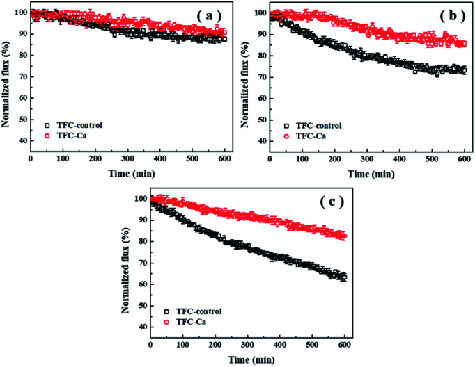
Fouling experiments were performed with the feed solution containing 50 mM NaCl and 1.0 mM Ca2+. The concentration of organic substances in the feed solution was fixed at 200 mg L−1. The flux decline curves for TFC-control and TFC-Ca membranes against different organic foulants (BSA, HA and SA) are shown in Fig. 1. As can be seen, the permeation fluxes of both the TFC-control and the TFC-Ca membranes were not drastically affected by the presence of BSA during the 600 min of experimental period (Fig. 1a). It indicates that BSA is difficult to attach to the TFC FO membranes (especially the TFC-Ca membrane), which led to a minor flux decline. In the case of HA fouling (Fig. 1b), the water flux of TFC-control and TFC-Ca membranes decreased by 26.7% and 14.3% after 600 min of operation, respectively. As for SA fouling (Fig. 1c), the TFC-control exhibited a more severe membrane fouling phenomenon with the final flux decline reaching to 36.7%, while the TFC-Ca membrane showed a substantially improved tolerance to SA fouling, as witnessed by the only 17.3% of flux decline at the end of the fouling experiment.
Fig. 1. Flux decline curves of TFC-control membrane and TFC-Ca membrane under different organic matters for (a) BSA was used as organic foulant, (b) HA used as organic foulant and (c) SA used as organic foulant. The concentration of organic foulant was 200 mg L−1 in the feed solution containing 50 mM NaCl and 1.0 mM Ca2+.
Generally, HA and SA, especially the SA can cause more severe membrane fouling for the TFC FO membrane as compared with BSA. The carboxylic acidity of BSA was stabilized at 1 meq. g−1, whereas the stabilized acidities of HA and SA were at 3.3 meq. g−1 and 3.5 meq. g−1, respectively.11,41,42 Therefore, the presence of Ca2+ in feed solution would not affect BSA fouling significantly, due to the low content of carboxylic groups in BSA, which greatly reduces the possibility of forming complexes and a cross-linked fouling layer on the membrane surface. To the contrary, SA is a linear copolymer of mannuronic and guluronic acids that contain abundant carboxylic functional groups. Ca2+ can bind preferentially to both the carboxylic groups on SA molecule and that on membrane surface in a highly cooperative manner, thus form a highly cross-linked fouling layer on the membrane surface via Ca2+ bridging effect.11,41,43 As compared with TFC-control membrane, the TFC-Ca membrane displays a strong anti-fouling capacity to the SA/HA present in the feed solution. This is due to that much less carboxyl group sites are available in the TFC-Ca membrane, as the in situ Ca2+ addition during IP process preoccupied the carboxyl groups on the polyamide layer via intra-bridging effect, and effectively decreased the inter-adhesion between membrane and SA/HA, thus resulting in mitigated membrane fouling. Consistently, as shown in Table 2, the interfacial adhesion energy and cohesion energy of TFC-control membrane for SA are −18.13 and −14.83 mJ m−2, respectively; however, the corresponding interfacial energies of TFC-Ca membrane for SA are 3.98 and 1.31 mJ m−2, respectively. Both the values of interfacial adhesion energy and cohesion energy turn from negative to positive, and the change trend of membrane fouling for the TFC-Ca membrane relative to TFC-control membrane is closely related to that of the calculated interfacial free energies. Conclusively, weakening the interfacial interaction between membrane and foulants can result in less accumulation of the foulants onto membrane surface, which leads to reduced membrane flux decline.
3.3. Characterization of the fouled membrane
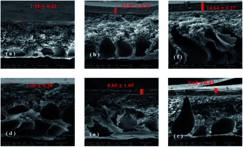
Fig. 2 shows a closer examination of the membranes fouled by different organic substances using SEM. Based on the cross-section observation of the fouled membranes, it can be clearly seen that different amounts of organic foulants had been deposited on the TFC-control and TFC-Ca membranes (parts (a–c) and (d–f) of Fig. 2). Fig. 2a and d showed that few BSA were accumulated on the surface of both membranes, this was in coincidence with that the permeation fluxes of the TFC-control and TFC-Ca membranes was barely influenced by the presence of BSA in feed solution as illustrated in Fig. 1. However, as shown in Fig. 2b–c and Fig. 2e–f, both HA and SA led to the formation of a much thicker fouling layer on the TFC-control membrane than that on the TFC-Ca membrane, and as a result the water flux was significantly decreased. This phenomenon is consistent with the XDLVO analysis, i.e. the interfacial free energies of TFC-control membrane for HA and SA are calculated to be higher than that of the TFC-Ca membrane. For the TFC-Ca membrane, the thicknesses of the fouling layers were 8.85 ± 1.05 and 9.62 ± 0.43 μm for HA and SA, respectively. While for the TFC-control membrane, a significant increase of the thickness to 12.97 ± 0.31 (for HA) and 14.64 ± 0.27 μm (for SA) was observed. The results indicated that a dense fouling layer was formed on the TFC-control membrane due to the strong interactions between the membrane surface and organic foulants HA/SA.
Fig. 2. Cross-section observation of fouling TFC-control membranes (a–c) and TFC-Ca membranes (d–f) by SEM, (a and d): BSA as model organic substance, (b and e): HA as model organic substance, (c and f): SA as model organic substance.
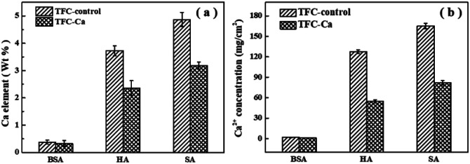
The fouled membranes were further subjected to elemental analysis by using EDX, as shown in Fig. 3a. The EDX results confirmed the deposition of Ca2+ in the organic fouling layer over the membrane surface, and higher elemental percentage of Ca was recorded for the fouling layer of TFC-control membrane than that of the TFC-Ca membrane.
Fig. 3. The amount of Ca2+ accumulated on the fouled TFC-control membranes and TFC-Ca membranes, (a) analyzed by EDX, (b) analyzed by ICP-OES.
ICP-OES analysis was further performed after the fouling membranes being soaked in ultrapure water, which can be used to reflect the overall concentration of Ca2+ accumulated in the fouling layer. Fig. 3b demonstrated that only a small amount of Ca2+ was present in the fouling layer of TFC-Ca membrane. However, a significantly higher amount of Ca2+ was identified to accumulate in the fouling layer of TFC-control membrane, especially for the cases of HA and SA fouling. Multivalent cations have a high tendency to form complexes with negatively charged components (i.e., membranes or moieties), resulting in a thick and dense fouling layer.44–46 TFC-control membrane has abundant surface characteristic functional groups especially carboxyl groups, it can enhance the adsorption capacity of organic foulants and thus induce more severe membrane fouling.
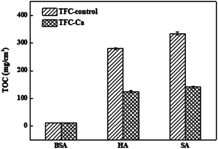
Fig. 4 provides a summary of the content of organic substances on the fouled membranes. For the TFC-Ca membrane, the organic content accumulated on the membrane surface after 600 min of operation were 10.41 mg cm−2 for BSA, 123.50 mg cm−2 for HA and 140.50 mg cm−2 for SA, respectively, which were considerably lower than the 11.24 mg cm−2 (BSA), 279.75 mg cm−2 (HA) and 414.75 mg cm−2 (SA) for the TFC-control membrane, respectively. In general, BSA deposition on the membrane surface was much smaller than the HA and SA, and exhibited a negligible difference between TFC-control and TFC-Ca membranes. Whereas for HA/SA fouling, the organic deposition on the TFC-control membrane were much severer than that on the TFC-Ca membrane. The significantly reduced deposition of organic substances suggests an intrinsic antifouling property of the TFC-Ca membrane. Both the thickness of fouling layer and the accumulation of organic foulants, as well as the Ca observed from EDX and ICP-OES analysis, confirmed that the properties of the membrane surface can drastically influence the membrane fouling behaviour,47 which were in good accordance with the variation trend of the flux curves (Fig. 1).
Fig. 4. The accumulated organic foulants on the fouled TFC-control membrane and TFC-Ca membranes were analyzed by TOC after the fouling experiment.
3.4. Fouling reversibility
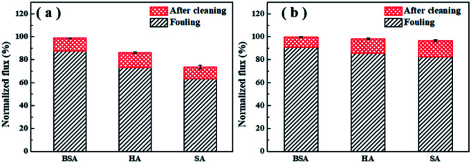
Membrane cleaning was performed by simple surface flushing with ultrapure water for 1 h. The decrease of water flux after fouling and the recovery of flux after cleaning are presented in Fig. 5 as normalized value. It was noticed that the TFC-Ca membrane showed higher cleaning efficiency and achieved higher water flux recovery than the TFC-control membrane (Fig. 5b). Under the experimental conditions used in the work, the water flux of fouled TFC-Ca membrane could be almost fully restored, which was in distinct comparison with the fouling irreversibility caused by HA/SA for the TFC-control membrane. It is recognized that the effectiveness of membrane cleaning will depend on the severity of foulant–membrane and foulant–foulant interactions. The positive interfacial free energies of TFC-Ca membrane with different organic foulants indicate the weakened interactions of foulant–membrane and foulant–foulant, which endows the membrane with much better cleaning efficiency.
Fig. 5. Normalized water fluxes of the TFC-control membranes (a) and the TFC-Ca membranes (b) after fouling and after physical cleaning.
4. Conclusion
The fouling behaviour of TFC-Ca membrane and TFC-control membrane against different organic foulants were systematically analyzed in this work. The following conclusions could be drawn:
(1) A strong correlation between TFC-Ca membrane fouling and interfacial free energy was observed, indicating that the interactions between membrane surface and organic foulants play an important role in determining the rate and extent of organic fouling.
(2) With regard to a thick fouling layer on the TFC-control membranes via the chelation, the TFC-Ca membranes can effectively reduce the membrane–Ca2+–foulant interaction.
(3) It was fully proved that the sequestration of foulant–membrane bridging sites could effectively improve the antifouling properties due to the different density of carboxyl groups in organic matters and the Ca2+ pre-occupying carboxyl groups strategy in TFC-Ca membrane.
Conflicts of interest
There are no conflicts of interest to declare.
Supplementary Material
Acknowledgments
This work was supported by the National Natural Science Foundation of China (No. 51908181 & No. 51678187), the Natural Science Foundation of Hebei Province (No. E2019202011 and No. E2019202012), and the Science and Technology Research Program for Colleges and Universities in Hebei Province (No. QN2019022).
Electronic supplementary information (ESI) available. See DOI: 10.1039/c9ra06272f
References
- Cath T. Childress A. Elimelech M. Forward osmosis: principles, applications, and recent developments. J. Membr. Sci. 2006;281:70–87. doi: 10.1016/j.memsci.2006.05.048. [DOI] [Google Scholar]
- Zhao S. Zou L. Tang C. Y. Mulcahy D. Recent developments in forward osmosis: opportunities and challenges. J. Membr. Sci. 2012;396:1–21. doi: 10.1016/j.memsci.2011.12.023. [DOI] [Google Scholar]
- Lutchmiah K. Verliefde A. R. D. Roest K. Rietveld L. C. Cornelissen E. R. Forward osmosis for application in wastewater treatment: a review. Water Res. 2014;58:179–197. doi: 10.1016/j.watres.2014.03.045. [DOI] [PubMed] [Google Scholar]
- Gao Y. Fang Z. Liang P. Huang X. Direct concentration of municipal sewage by forward osmosis and membrane fouling behaviour. Bioresour. Technol. 2018;247:730–735. doi: 10.1016/j.biortech.2017.09.145. [DOI] [PubMed] [Google Scholar]
- McGinnis R. L. Elimelech M. Energy requirements of ammonia–carbon dioxide forward osmosis desalination. Desalination. 2007;207:370–382. doi: 10.1016/j.desal.2006.08.012. [DOI] [Google Scholar]
- Tow E. W. Lienhard V J. H. Quantifying osmotic membrane fouling to enable comparisons across diverse processes. J. Membr. Sci. 2016;511:92–107. doi: 10.1016/j.memsci.2016.03.040. [DOI] [Google Scholar]
- Xie M. Lee J. Nghiem L. D. Elimelech M. Role of pressure in organic fouling in forward osmosis and reverse osmosis. J. Membr. Sci. 2015;493:748–754. doi: 10.1016/j.memsci.2015.07.033. [DOI] [Google Scholar]
- Chekli L. Phuntsho S. Kim J. E. Kim J. Choi J. Y. Choi J. Kim S. Kim J. H. Hong S. Sohn J. Shon H. K. A comprehensive review of hybrid forward osmosis systems: performance, applications and future prospects. J. Membr. Sci. 2016;497:430–449. doi: 10.1016/j.memsci.2015.09.041. [DOI] [Google Scholar]
- Wang Z. Tang J. Zhu C. Dong Y. Wang Q. Wu Z. Chemical cleaning protocols for thin film composite (TFC) polyamide forward osmosis membranes used for municipal wastewater treatment. J. Membr. Sci. 2015;475:184–192. doi: 10.1016/j.memsci.2014.10.032. [DOI] [Google Scholar]
- She Q. Wang R. Fane A. G. Tang C. Y. Membrane fouling in osmotically driven membrane processes: a review. J. Membr. Sci. 2016;499:201–233. doi: 10.1016/j.memsci.2015.10.040. [DOI] [Google Scholar]
- Mi B. Elimelech M. Chemical and physical aspects of organic fouling of forward osmosis membranes. J. Membr. Sci. 2008;320:292–302. doi: 10.1016/j.memsci.2008.04.036. [DOI] [Google Scholar]
- Ly Q. V. Hu Y. Li J. Cho J. Hur J. Characteristics and influencing factors of organic fouling in forward osmosis operation for wastewater applications: a comprehensive review. Environ. Int. 2019;129:164–184. doi: 10.1016/j.envint.2019.05.033. [DOI] [PubMed] [Google Scholar]
- Mazlana N. M. Marchetti P. Maples H. A. Gu B. Karan S. Bismarck A. Livingston A. G. Organic fouling behaviour of structurally and chemically different forward osmosis membranes – a study of cellulose triacetate and thin film composite membranes. J. Membr. Sci. 2016;520:247–261. doi: 10.1016/j.memsci.2016.07.065. [DOI] [Google Scholar]
- Zhang B. Song X. Nghiem L. D. Li G. Luo W. Osmotic membrane bioreactors for wastewater reuse: performance comparison between cellulose triacetate and polyamide thin film composite membranes. J. Membr. Sci. 2017;539:383–391. doi: 10.1016/j.memsci.2017.06.026. [DOI] [Google Scholar]
- Akther N. Sodiq A. Giwa A. Daer S. Arafat H. A. Hasan S. W. Recent advancements in forward osmosis desalination: a review. Chem. Eng. J. 2015;281:502–522. doi: 10.1016/j.cej.2015.05.080. [DOI] [Google Scholar]
- Katsoufidou K. Yiantsios S. G. Karabelas A. J. Experimental study of ultrafiltration membrane fouling by sodium alginate and flux recovery by backwashing. J. Membr. Sci. 2007;300:137–146. doi: 10.1016/j.memsci.2007.05.017. [DOI] [Google Scholar]
- Mo Y. Tiraferri A. Yip N. Y. Adout A. Huang X. Elimelech M. Improved Antifouling Properties of Polyamide Nanofiltration Membranes by Reducing the Density of Surface Carboxyl Groups. Environ. Sci. Technol. 2012;46:13253–13261. doi: 10.1021/es303673p. [DOI] [PubMed] [Google Scholar]
- Bao X. Wu Q. Shi W. Polyamidoamine dendrimer grafted forward osmosis membrane with superior ammonia selectivity and robust antifouling capacity for domestic wastewater concentration. Water Res. 2019;153:1–10. doi: 10.1016/j.watres.2018.12.067. [DOI] [PubMed] [Google Scholar]
- Zhang X. Tian J. Gao S. Zhang Z. Cui F. Tang C. Y. In situ surface modification of thin film composite forward osmosis membranes with sulfonated poly(arylene ether sulfone) for anti-fouling in emulsified oil/water separation. J. Membr. Sci. 2017;527:26–34. doi: 10.1016/j.memsci.2017.01.002. [DOI] [Google Scholar]
- Liu C. Lee J. Small C. Ma J. Elimelech M. Comparison of organic fouling resistance of thin-film composite membranes modified by hydrophilic silica nanoparticles and zwitterionic polymer brushes. J. Membr. Sci. 2017;544:135–142. doi: 10.1016/j.memsci.2017.09.017. [DOI] [Google Scholar]
- Nguyen A. Zou L. Priest C. Evaluating the antifouling effects of silver nanoparticles regenerated by TiO2 on forward osmosis membrane. J. Membr. Sci. 2014;454:264–271. doi: 10.1016/j.memsci.2013.12.024. [DOI] [Google Scholar]
- Xue W. Sint K. K. K. Ratanatamskul C. Praserthdam P. Yamamoto K. Binding TiO2 nanoparticles to forward osmosis membranes via MEMO–PMMA–Br monomer chains for enhanced filtration and antifouling performance. RSC Adv. 2018;8:19024–19033. doi: 10.1039/C8RA03613F. [DOI] [PMC free article] [PubMed] [Google Scholar]
- Sun W. Shi J. Chen C. Li N. Xu Z. Li J. Lv H. Qian X. Zhao L. A review on organic–inorganic hybrid nanocomposite membranes: a versatile tool to overcome the barriers of forward osmosis. RSC Adv. 2018;8:14–156. doi: 10.1039/c7ra12835e. [DOI] [PMC free article] [PubMed] [Google Scholar]
- Tiraferri A. Kang Y. Giannelis E. P. Elimelech M. Superhydrophilic Thin-Film Composite Forward Osmosis Membranes for Organic Fouling Control: Fouling Behavior and Antifouling Mechanisms. Environ. Sci. Technol. 2012;46:11135–11144. doi: 10.1021/es3028617. [DOI] [PubMed] [Google Scholar]
- Li L. Wang X. Xie M. Wang Z. Li X. Ren Y. In situ extracting organic-bound calcium: a novel approach to mitigating organic fouling in forward osmosis treating wastewater via gradient diffusion thin-films. Water Res. 2019;156:102–109. doi: 10.1016/j.watres.2019.03.018. [DOI] [PubMed] [Google Scholar]
- Hao X. Gao S. Tian J. Sun Y. Cui F. Tang C. Y. Calcium-Carboxyl Intrabridging during Interfacial Polymerization: A Novel Strategy to Improve Antifouling Performance of Thin Film Composite Membranes. Environ. Sci. Technol. 2019;53:4371–4379. doi: 10.1021/acs.est.8b05690. [DOI] [PubMed] [Google Scholar]
- Liu B. Liu X. Shi S. Huang R. Su R. Qi W. He Z. Design and mechanisms of antifouling materials for surface plasmon resonance sensors. Acta Biomater. 2016;40:100–118. doi: 10.1016/j.actbio.2016.02.035. [DOI] [PubMed] [Google Scholar]
- Motsa M. M. Mamba B. B. Verliefde A. R. D. Forward osmosis membrane performance during simulated wastewater reclamation: fouling mechanisms and fouling layer properties. J. Water Process Eng. 2018;23:109–118. doi: 10.1016/j.jwpe.2018.03.007. [DOI] [Google Scholar]
- Zhao P. Gao B. Yue Q. Liu P. Shon H. K. Fatty acid fouling of forward osmosis membrane: effects of pH, calcium, membrane orientation, initial permeate flux and foulant composition. J. Environ. Sci. 2016;46:55–62. doi: 10.1016/j.jes.2016.02.008. [DOI] [PubMed] [Google Scholar]
- Meng X. Tang W. Wang L. Wang X. Huang D. Chen H. Zhang N. Mechanism analysis of membrane fouling behavior by humic acid using atomic force microscopy: effect of solution pH and hydrophilicity of PVDF ultrafiltration membrane interface. J. Membr. Sci. 2015;487:180–188. doi: 10.1016/j.memsci.2015.03.034. [DOI] [Google Scholar]
- Van Oss C. J., Interfacial Forces in Aqueous Media, Marcel Dekker, Inc., New York, NY, 1994 [Google Scholar]
- Van Oss C. J. Acid–base interfacial interactions in aqueous media. Colloids Surf., A. 1993;78:1–49. doi: 10.1016/0927-7757(93)80308-2. [DOI] [Google Scholar]
- Subramani A. Hoek E. Direct observation of initial microbial deposition onto reverse osmosis and nanofiltration membranes. J. Membr. Sci. 2008;319:111–125. doi: 10.1016/j.memsci.2008.03.025. [DOI] [Google Scholar]
- Lin T. Lu Z. Chen W. Interaction mechanisms and predictions on membrane fouling in an ultrafiltration system, using the XDLVO approach. J. Membr. Sci. 2014;461:49–58. doi: 10.1016/j.memsci.2014.03.022. [DOI] [Google Scholar]
- Lin T. Lu Z. Chen W. Interaction mechanisms of humic acid combined with calcium ions on membrane fouling at different conditions in an ultrafiltration system. Desalination. 2015;357:26–35. doi: 10.1016/j.desal.2014.11.007. [DOI] [Google Scholar]
- Sun Y. Tian J. Zhao Z. Shi W. Liu D. Cui F. Membrane fouling of forward osmosis (FO) membrane for municipal wastewater treatment: a comparison between direct FO and OMBR. Water Res. 2016;104:330–339. doi: 10.1016/j.watres.2016.08.039. [DOI] [PubMed] [Google Scholar]
- Sun Y. Tian J. Song L. Gao S. Shi W. Cui F. Dynamic changes of the fouling layer in forward osmosis based membrane processes for municipal wastewater treatment. J. Membr. Sci. 2018;549:523–532. doi: 10.1016/j.memsci.2017.12.055. [DOI] [Google Scholar]
- Nguyen Q. Jeong S. Lee S. Characteristics of membrane foulants at different degrees of SWRO brine concentration by membrane distillation. Desalination. 2017;409:7–20. doi: 10.1016/j.desal.2017.01.007. [DOI] [Google Scholar]
- Zhang W. Dong B. Effects of physical and chemical aspects on membrane fouling and cleaning using interfacial free energy analysis in forward osmosis. Environ. Sci. Pollut. Res. 2018;25:21555–21567. doi: 10.1007/s11356-018-2239-0. [DOI] [PubMed] [Google Scholar]
- Yin W. Li X. Suwarno S. R. Cornelissen E. R. Chong T. H. Fouling behavior of isolated dissolved organic fractions from seawater in reverse osmosis (RO) desalination process. Water Res. 2019;159:385–396. doi: 10.1016/j.watres.2019.05.038. [DOI] [PubMed] [Google Scholar]
- Zhao F. Xu K. Ren H. Ding L. Geng J. Zhang Y. Combined effects of organic matter and calcium on biofouling of nanofiltration membranes. J. Membr. Sci. 2015;486:177–188. doi: 10.1016/j.memsci.2015.03.032. [DOI] [Google Scholar]
- Liu Y. Mi B. Effects of organic macromolecular conditioning on gypsum scaling of forward osmosis membranes. J. Membr. Sci. 2014;450:153–161. doi: 10.1016/j.memsci.2013.09.001. [DOI] [Google Scholar]
- Mo Y. Tiraferri A. Yip N. Y. Adout A. Huang X. Elimelech M. Improved antifouling properties of polyamide nanofiltration membranes by reducing the density of surface carboxyl groups. Environ. Sci. Technol. 2012;46:13253–13261. doi: 10.1021/es303673p. [DOI] [PubMed] [Google Scholar]
- Gryta M. The assessment of microorganism growth in the membrane distillation system. Desalination. 2002;142:79–88. doi: 10.1016/S0011-9164(01)00427-1. [DOI] [Google Scholar]
- Gryta M. Fouling in direct contact membrane distillation process. J. Membr. Sci. 2008;325:383–394. doi: 10.1016/j.memsci.2008.08.001. [DOI] [Google Scholar]
- Nguyen Q. M. Jeong S. Lee S. Characteristics of membrane foulants at different degrees of SWRO brine concentration by membrane distillation. Desalination. 2017;409:7–20. doi: 10.1016/j.desal.2017.01.007. [DOI] [Google Scholar]
- Cruz-Silva R. Takizawa Y. Nakaruk A. Katouda M. Yamanaka A. Ortiz-Medina J. et al., New Insights in the Natural Organic Matter Fouling Mechanism of Polyamide and Nanocomposite Multiwalled Carbon Nanotubes-Polyamide Membranes. Environ. Sci. Technol. 2019;53:6255–6263. doi: 10.1021/acs.est.8b07203. [DOI] [PubMed] [Google Scholar]
Associated Data
This section collects any data citations, data availability statements, or supplementary materials included in this article.


