Abstract
We show that N,N-dimethylformamide-stabilized Pd nanoclusters (NCs) have high catalytic activity in the reaction of substituted 2-iodoanilines with alkynes to give 2,3-disubstituted indoles. This indole synthesis does not require phosphine ligands and proceeds with low Pd catalyst loadings. The Pd NCs were separated from the mixture after the reaction, and recycled at least three times. Transmission electron microscopy images showed that the Pd particle size before the reaction was 1.5–2.5 nm. The particle size after the reaction was 2–3 nm. X-ray photoelectron spectroscopy showed that the binding energy of the Pd NCs before the reaction was 335.0 eV.
Pd NCs serve recyclable and highly active catalyst to indole synthesis.
Introduction
Indoles are important building blocks in many areas of organic synthesis.1 Indole moieties are common in bioactive substances,2 optically responsive materials,3 electronic materials,4 and fluorescent polymer sensors.5 Many methods for the synthesis of indole derivatives have been developed.6–16 Fischer and co-workers reported that the reactions of aryl hydrazines with ketones gave 2,3-disubstituted indoles.7 Buchwald prepared 2,3-disubstituted indoles from hydrazines and aryl halides and ketones using a Pd catalyst.8 Bischler reported a reaction of aniline with α-haloketones.9 Fukuyama reported radical cyclization of 2-alkenylthioanilides using Sn radicals.10 An Ir-catalyzed oxidative cyclization of amino alcohols has been reported.11 Transition metals coordinated with NHC-ligands can catalyze C–H activation of substituted anilines.12 Recently, easily available 2-haloanilines were used to prepare substituted indoles. The reaction of 2-iodoanilines with vinyl sulfones yielded 3-substituted indoles under Pd catalysis.13 In 1991, Larock reported an efficient and powerful method for obtaining 2,3-disubstituted indoles, with a Pd complex as the catalyst.14 Li and co-workers reported the synthesis of mono-substituted indoles, catalyzed by Pd nanoparticles in metal–organic framework cages.15
Transition metals or ligands were used in these reactions.8,10–15 From an industrial point of view, reducing the catalyst loading is highly desirable. Transition-metal nanoclusters (NCs) have attracted attention for use in industrial, chemical, and medical research.16
We previously reported the preparation of N,N-dimethylformamide (DMF)-stabilized transition-metal nanoparticles via reduction with DMF.17 The obtained metal NCs showed high catalytic activity in Suzuki–Miyaura cross-coupling, Mizoroki–Heck coupling,16 Migita–Kosugi–Stille coupling,18 and Ullmann coupling reactions.19 The DMF-stabilized metal nanoparticles gave high turnover numbers and could be recovered after the reactions.16–19 Furthermore, the DMF-stabilized Pd NCs were relatively long-lived at high temperatures compared with typical heterogeneous catalysts. Our work has focused on reducing catalyst loadings or reactions by using transition-metal NCs as catalysts.
In this paper, we report the synthesis of 2,3-disubstituted indoles from 2-iodoanilines and internal alkynes, catalyzed by DMF-stabilized Pd NCs. This reaction proceeded under ligand-free conditions at low catalyst loadings. The Pd NCs were recycled at least three times.
Results and discussion
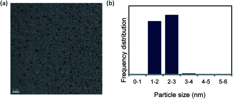
Pd NCs were prepared via reduction with DMF.18 The Pd NCs were examined using transmission electron microscopy (TEM). The TEM image and particle size distribution indicated that the Pd NC particle size was 1.5–2.5 nm (Fig. 1).
Fig. 1. (a) TEM image of DMF-stabilized Pd nanoclusters (scale bar = 5 nm) and (b) nanoparticle size distribution.
Fourier-transfer infrared (FT-IR) spectra of the DMF molecules and DMF-protected Pd NCs were obtained. The Pd NCs gave an absorption peak at around 1680 cm−1. This peak corresponds to the ν(C O) vibration of DMF molecules and was shifted relative to that for pure DMF. This indicates that the DMF molecules interacted with the Pd NCs (Fig. S1†).20,21
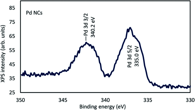
The electron states of the DMF-protected Pd NCs were determined using X-ray photoelectron spectroscopy (XPS). The binding energy (BE) 335.0 eV of Pd 3d5/2 for the Pd NCs, namely 335.0, indicated the presence of zero-valent Pd in the Pd NCs. The BE of Pd 3d5/2 for the Pd NCs was −3.2 eV lower than that of Pd 3d5/2 in PdCl2 (338.2 eV) (Fig. 2).22
Fig. 2. XPS spectra of Pd NCs.
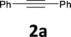
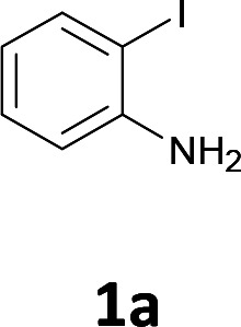
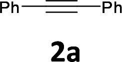
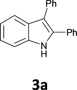
The results are shown in Table 1. The reaction of 2-iodoaniline (1a, 0.5 mmol) with diphenylacetylene (2a, 0.5 mmol) in the presence of Pd NCs (3.0 × 10⁻¹ mol%; prepared as previously reported18), K2CO3 (1.5 mmol), and NaCl (1.5 mmol) in DMF at 135 °C for 48 h under Ar was used as a model reaction; 2,3-diphenylindole (3a) was obtained. The use of the low catalyst loading (3.0 × 10⁻¹ mol%) achieved the high catalytic activity, which demonstrate the superiority to the turnover number (TON) for the formation of 3a was 3.2 × 10² (mol)/Pd NCs (mol), which show the advantage of this Pd NCs in comparison with other known catalytic system.8,11,13–15
Pd NC-catalyzed synthesis of 2,3-diphenylindole (3a) from 2-iodoaniline (1a) and diphenylacetylene (2a)a.

| |||||
|---|---|---|---|---|---|
| Entry | Solvent | Additive | Base | X | Yieldb (%) |
| 1 | DMF | NaCl | K2CO3 | 0.3 | 96 (88) |
| 2 | DMF/H2O (1 : 1) | NaCl | K2CO3 | 0.3 | Trace |
| 3 | NMP/H2O (1 : 1) | NaCl | K2CO3 | 0.3 | 28 |
| 4 | MeOH/H2O (1 : 1) | NaCl | K2CO3 | 0.3 | Trace |
| 5 | DMF | LiCl | K2CO3 | 0.3 | Trace |
| 6 | DMF | n-Bu4NCl | K2CO3 | 0.3 | Trace |
| 7 | DMF | None | K2CO3 | 0.3 | 69 |
| 8 | DMF | NaCl | KOAc | 0.3 | 51 |
| 9 | DMF | NaCl | Cs2CO3 | 0.3 | 24 |
| 10 | DMF | NaCl | Na2CO3 | 0.3 | 87 |
| 11 | DMF | NaCl | K2CO3 | 0.03 | Trace |
| 12 | DMF | NaCl | K2CO3 | None | n.d. |
| 13c | DMF | NaCl | K2CO3 | 1.0 | 47 |
| 14d | DMF | NaCl | K2CO3 | 0.3 | 88 |
| 15e | DMF | NaCl | K2CO3 | 0.3 | Trace |
Conditions: 1a (0.5 mmol), 2a (0.5 mmol), Pd NCs (3.0 × 10⁻¹ mol%), solvent (2 mL), additive (1.5 mmol), base (1.5 mmol), 135 °C, 48 h.
GC yields based on limiting reagent used. The number in parentheses shows the isolated yield.
PdCl2 (1.0 mol%) was used instead of Pd NCs.
K2CO3 (0.25 mmol).
Hg (5 equiv.) was used.
We optimized the conditions for Pd-NC-catalyzed Larock indole synthesis; the results are shown in Table 1. We examined the effects of the solvent. DMF was the most effective solvent and 3a was obtained in 88% isolated yield (entry 1). Next, we examined mixed solvents, namely DMF/H2O (1 : 1) (entry 2), N-methylpyrrolidone (NMP)/H2O (1 : 1) (entry 3), and MeOH/H2O (1 : 1) (entry 4). When DMF/H2O (1 : 1) was used, a trace amount of 3a was obtained (entry 2). When NMP/H2O (1 : 1) was used, 3a was obtained in 28% yield (entry 3). When MeOH/H2O was used, a trace amount of 3a was obtained (entry 4).
Next, we examined the effect of using LiCl and n-Bu4NCl instead of NaCl as additives. LiCl and n-Bu4NCl are traditionally used as additives in the Larock indole synthesis.14 In the present method, NaCl was the best additive (entries 5 and 6). Without NaCl, product 3a was obtained in 69% yield (entry 7). The addition of salts such as NaCl enhanced the catalytic activity by the formation of a chloride-ligated zerovalent palladium species as was reported (as catalytically active species) in the palladium-complex catalyzed Larock indole synthesis.14b
Next, various bases were tested. When KOAc was used, 3a was obtained in 51% yield (entry 8). Cs2CO3 gave 3a in 24% yield (entry 9). When Na2CO3 was used, 3a was obtained in 87% yield (entry 10).
When the amount of Pd NCs was reduced to 3.0 × 10⁻² mol%, a trace amount of 3a was obtained (entry 11).
Next, the effects of the Pd NCs were examined. The product 3a was not observed in the absence of Pd NCs (entry 12).
When PdCl2 (1.0 mol%; the precursor used to prepare the DMF-stabilized Pd NCs) was used, the reaction was ineffective and the product yield was low (entry 13). The catalytic activity was therefore derived from the Pd NCs, not from PdCl2.
When K2CO3 (0.25 mmol) was used, 3a was obtained in 88% yield (entry 14). The conditions in Table 1, entry 14 were used in recycling experiments. The Pd NC particle size after the reaction was determined.
The stability of the Pd NCs was further investigated by conducted poisoning tests with Hg (5 equiv.) under the conditions in Table 1, entry 1. The conversions of 1a and 2a were 38% and 26%, respectively, and product 3a was obtained in trace amounts. These results indicate that the catalytic activity of the Pd NCs was decreased by forming an amalgam with Hg.
A TEM image was used to determine the effects of DMF molecules on the Pd NCs after the reaction performed under the conditions in Table 1, entry 14.
The TEM image showed the presence of Pd in the sample; this was confirmed using inductively coupled plasma atomic emission spectroscopy (ICP-AES).
The sample for ICP-AES was obtained as follows. The DMF in the mixture after the reaction under the conditions in Table 1, entry 1 was removed by evaporation, and the sample was redissolved in CH2Cl2. Next, K2CO3 and NaCl were removed from the sample solution by filtration with a membrane filter, using CH2Cl2. Finally, CH2Cl2 was removed by evaporation and the sample was redissolved in MeOH. This sample was analyzed using ICP-AES to determine the concentrations of Pd, Na, and K.
The concentrations of Pd and Na were 3.4 and 2.7 ppm, respectively. The concentration of K was below the detection limit. The ICP-AES data charts and standard curve are shown in Fig. S2–S4.† These results indicated that Pd was the main component in the sample. The sample prepared by the same method was analyzed by TEM. The results show aggregation of some of the Pd NCs (Fig. S5†).
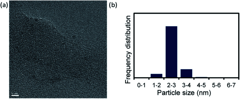
We used TEM images (Fig. 3a and S6†) to investigate the Pd NC particle size after the reaction performed under the conditions in Table 1, entry 14. The Pd NC particle size distribution was 2–3 nm, i.e., the particles were slightly larger after the reaction. However, inhibition of Ostwald ripening21,23 during the catalytic reaction led to the nanoparticles retaining their original size, <3 nm.
Fig. 3. (a) TEM image of Pd NCs after reaction under conditions in Table 1, entry 14 (scale bar = 5 nm) and (b) nanoparticle size distribution.
Dynamic light scattering (DLS) measurements showed that the Pd NCs had an average particle diameter of 2.3 nm, (Fig. S8†).
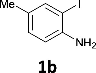
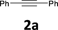
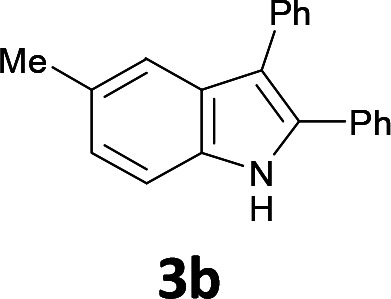
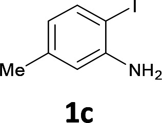
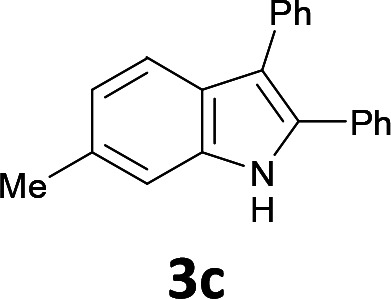
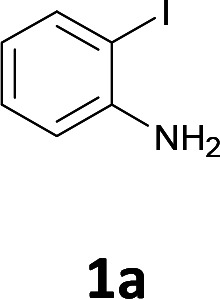
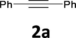
The substrate scope was examined by performing reactions between haloanilines 1 and internal alkynes 2 under the conditions in Table 1, entry 1. The results are shown in Table 2. The reaction of 2-iodoaniline (1a) with 2,3-diphenylacetylene (2a) gave 2,3-diphenylindole (3a) in excellent yield. A comparison of entries 1 and 2 shows how the electronic effects of the substituents in haloaniline 1 affect the reaction. The reactions of haloanilines bearing electron-donating groups, e.g., 4-Me (1b) and 5-Me (1c), with diphenylacetylene (2a), gave the corresponding indoles 3b and 3c in moderate and excellent yields, respectively (entries 1 and 2). However, when the substituents were electron-withdrawing groups such as 4-CF3 and 5-Cl, the reaction became sluggish.
Pd NC-catalyzed 2,3-disubstituted indole synthesis of various halo anilines 1 and internal alkynes 2a.

| ||||
|---|---|---|---|---|
| Entry | Aryl halide | Alkyne | Product | Yieldb (%) |
| 1 |
|
|
|
77 |
| 2 |
|
|
|
71 |
| 3 |
|
|
|
80 |
| 4 |
|
|
|
66 |
| 5 |
|
|
|
88 (4 : 1) |
| ||||
| 6 |
|
|
|
95 |
| 7 |
|
|
|
49 |
| 8 |
|
|
|
30 (2 : 1) |
| ||||
Conditions: same as in Table 1, entry 1.
Isolated yields.
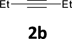
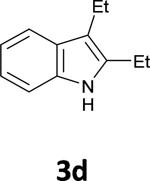
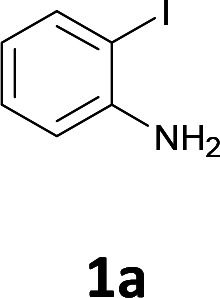
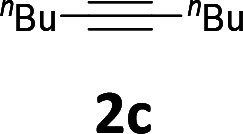
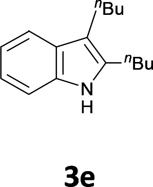
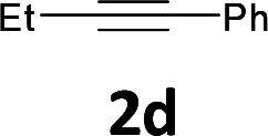
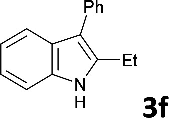
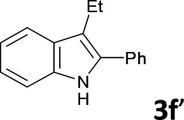
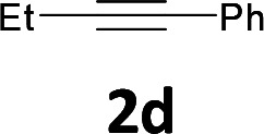
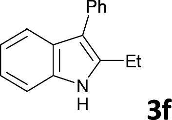
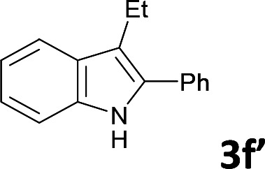
Various aliphatic and aromatic alkynes were good substrates for the reactions of alkynes 2 with 2-iodoaniline (1a). 3-Hexyne (2b) and 5-decyne (2c) reacted with 2-iodoaniline (1a) to give the corresponding 2,3-disubstituted indoles 3d and 3e in good yields (entries 3 and 4). The reaction of the asymmetric alkyne 1-phenyl-1-butyne (2d) gave the corresponding products 3f and 3f′ in 88% yield as a mixture of regioisomers (3f : 3f′ = 4 : 1; entry 5). When terminal alkynes such as ethynylbenzene were used in the reaction, the corresponding products were not obtained; the related Sonogashira coupling reaction also did not proceed with the Pd NCs. An alkyne bearing a trimethylsilyl group, namely 1-phenyl-2-(trimethylsilyl)acetylene, was used to examine the effects of steric hindrance; the desired product was not obtained. This lack of reactivity is assumed to be the result of steric hindrance.
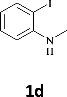
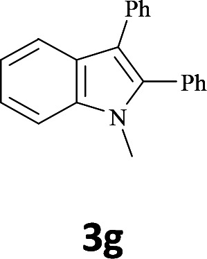
The secondary amine N-methyl-2-iodoaniline (1d) reacted with diphenylacetylene (2a) to give the corresponding indole 3g in 95% yield (entry 6).
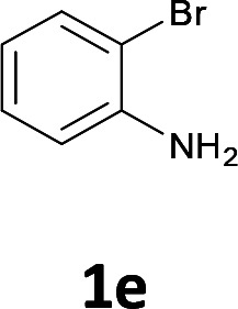
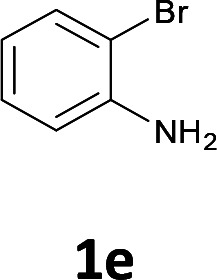
We also used easily accessible 2-bromoaniline (1e) instead of 2-iodoaniline, and obtained 3a in good yield (entry 7). When the asymmetric alkyne 1-phenyl-1-butyne (2d) was used, the corresponding products 3f and 3f′ were obtained in 30% yield; the regioisomer ratio 3f : 3f′ was 2 : 1 (entry 8).
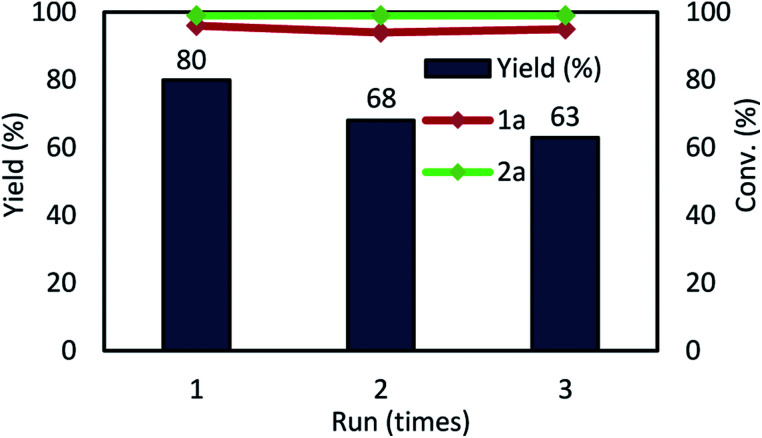
Next, we examined the recyclability of the catalyst. The reaction was performed using substrates of 1a and 2a. In the first cycle, the desired product 3a was obtained in 88% yield, under the conditions in Table 1, entry 14 (step 1 to step 2 in Fig. 4). Next, the Pd NCs were separated from 3a using a mixed solvent (hexane : ethyl acetate = 77 : 23, 5 mL × seven times; upper phase); the Pd NCs remained in the DMF solvent (bottom phase) (step 3). The hexane : ethyl acetate ratio was important for achieving complete separation of the Pd NCs from 3a. In the next step, the DMF solution containing the Pd NCs was filtered through a cotton plug to remove K2CO3 and NaCl from the DMF solution. The DMF was removed under vacuum and the residue was redissolved in DMF (2 mL); these Pd NCs in DMF were used for the next catalytic reaction (step 4). In the second cycle, product 3a was obtained in 80% yield (Fig. 5). Re-addition of NaCl and K2CO3 is necessary for achieving high catalytic activity in the recycling experiments. At this time, large amount of insoluble solid material was formed during the course of multiple recycling experiments, which resulted in substantially decreasing the catalytic activity. Therefore, the resulting solid was removed by filtration in prior to the next catalytic recycling process.
Fig. 4. Photographs of catalyst-recycling procedure in indole synthesis under reaction conditions in Table 1, entry 14. Step 1: reaction mixture containing 1a, 2a, Pd NCs, K2CO3, and NaCl before the reaction. Step 2: mixture containing 3a after reaction (after first cycle). Step 3: hexane : ethyl acetate (77 : 23) mixed solvent was added (upper phase: mixed solvent containing 3a, bottom phase: DMF containing Pd NCs). Step 4: reaction mixture for next run, containing 1a, 2a, Pd NCs, K2CO3, and NaCl.
Fig. 5. Multiple catalyst recycling. Conditions: as given in Table 1, entry 14.
We performed ICP analysis and the concentration of Pd in the hexane/ethyl acetate phase was 6.2 ppm (Table S2, Fig. S10†). The catalyst metal leaching resulted in decreasing of the yield of 3a during the multiple recycling steps.
In contrast, the PdCl2 catalyst could not be recycled. Only 11% yield of the product 3a was obtained in the first cycle when PdCl2 was used instead of Pd NCs under the reaction conditions in Table 1, entry 14.
Conclusions
We have developed a useful catalytic system for the Larock indole synthesis, using DMF-protected Pd clusters, which can be easily prepared by simply heating the Pd NCs in DMF. This catalytic system does not require external ligands and the reaction was achieved at low catalyst loadings.
An advantage of this catalytic system is that the catalyst can be recycled at least three times without considerable loss of catalytic activity. The catalyst can be easily recovered by simple extraction with hexane–ethyl acetate/DMF (the Pd NCs move into the DMF phase). The recycled Pd NCs maintain high catalytic activity and the recovered catalyst does not need pre-activation for the next catalytic cycle.
This process provides a green method for the Larock indole synthesis. The amount of Pd NC catalyst used can be kept low by multiple recycling. The present ligandless DMF–Pd NC-catalyzed process could be extended to a wide range of organic transformations. This will be investigated in future work by our group.
Experimental section
1. General
GLC analysis was performed with a flame ionization detector using a 0.22 × 25 m capillary column (BP-5). 1H and 13C NMR spectra were recorded at 400 and 100 MHz, respectively, in CDCl3 with Me4Si as the internal standard. The products were characterized by 1H NMR and 13C NMR spectroscopies. All reagents were commercially available and used without further purification. The DMF-protected Pd NCs were prepared according to the reported method.18 TEM images were obtained with a JEOL JEM-ARM200F instrument at an accelerating voltage of 200 kV. X-ray photoelectron spectroscopy (XPS) spectrum was used JPS-9010MC with the Al Kα radiation. The measured spectra were calibrated by a C 1s electron peak (284.0 eV). ICP-AES was analyzed by a Shimadzu ICPS-8100.
Compounds 3a,243b,253c,263d,273e,283f,293f′,29 and 3g (ref. 30) are known compounds and have been reported previously.
2. Typical procedure for Pd NC-catalyzed indole synthesis of 1a with 2a (Table 1, entry 1)
A mixture of 2-iodoaniline (1a, 109 mg, 0.5 mmol), diphenylacetylene (2a, 89 mg, 0.5 mmol), K2CO3 (207 mg, 1.5 mmol), NaCl (88 mg, 1.5 mmol), Pd NCs in DMF (1.5 mL, 1 mM) as the catalyst, in DMF (0.5 mL) as the solvent was stirred at 135 °C for 48 h in an Ar atmosphere. To ensure reproducibility of the reaction, K2CO3 and NaCl were ground with an agate pestle and mortar before addition to the mixture. The product conversions and yields were estimated by GC from peak areas, based on an internal standard (n-nonane); product 3a was obtained in quantitative yield. The reaction mixture was extracted with water and ethyl acetate to separate the products from the Pd NCs and salts. Product 3a was isolated by column chromatography [silica gel (230–400 mesh), n-hexane and ethyl acetate as eluent] in 88% yield (119 mg).
3a (ref. 24 and 31)
White solid, mp = 115–116 °C (Lit.30 114–116 °C), 1H NMR (CDCl3, 400 MHz) δ 7.13–7.45 (m, 13H), 7.68 (d, J = 4 Hz, 1H), 8.19 (br, 1H); 13C NMR (CDCl3, 100 MHz) δ 110.9 (CH), 115.0 (C), 119.7 (CH), 120.4 (CH), 122.7 (CH), 126.2 (CH), 127.7 (CH), 128.2 (CH), 128.5 (2CH), 128.7 (CH), 128.8 (2CH), 130.2 (2CH), 132.7 (C), 134.1 (C), 135 (2C), 135.9 (C).
3b (ref. 25 and 32)
Beige solid, mp = 143–147 °C (Lit.31 151–152 °C), 1H NMR (CDCl3, 400 MHz) δ 2.31 (s, 3H), 6.92–7.34 (m, 13H), 7.85 (br, 1H); 13C NMR (CDCl3, 100 MHz) δ 21.52 (CH3), 110.56 (C), 114.55 (C), 119.17 (CH), 124.23 (CH), 126.10 (CH), 127.51 (CH), 128.06 (CH), 128.47 (CH), 128.58 (2CH), 128.93 (2CH), 129.66 (CH), 130.00 (C), 130.15 (2CH), 132.72 (C), 134.15 (2C), 135.20 (C).
3c (ref. 26 and 33)
Beige solid, mp = 102–106 °C (Lit.32 70–80 °C), 1H NMR (CDCl3, 400 MHz) δ 2.45 (s, 3H), 6.95–7.56 (m, 13H), 8.01 (br, 1H); 13C NMR (CDCl3, 100 MHz) δ 21.52 (CH3), 110.55 (CH), 114.56 (C), 119.16 (CH), 124.23 (CH), 126.10 (CH), 127.50 (CH), 128.06 (2CH), 128.46 (2CH), 128.58 (2CH), 128.80 (C), 128.94 (C), 129.66 (2CH), 130.16 (C), 132.76 (C), 134.16 (C), 135.21 (C).
3d (ref. 27)
Yellow oil, 1H NMR (CDCl3, 400 MHz) δ 1.19–1.23 (m, 6H), 2.64–2.72 (m, 4H), 7.04–7.20 (m, 3H), 7.51–7.53 (m, 2H); 13C NMR (CDCl3, 100 MHz) δ 14.5 (CH3), 15.8 (CH3), 17.3 (CH2), 19.3 (CH2), 110.3 (CH), 113.0 (C), 118.2 (CH), 118.9 (CH), 120.8 (CH), 128.4 (C), 135.2 (C), 136.1 (C).
3e (ref. 28)
Pale-yellow oil, 1H NMR (CDCl3, 400 MHz) δ 0.91–0.96 (m, 6H), 1.36–1.40 (m, 4H), 1.41–1.64 (m, 4H), 2.66–2.72 (m, 4H), 7.04–7.11 (m, 2H), 7.22–7.26 (m, 1H), 7.51 (d, J = 8.0 Hz, 1H), 7.65 (br, 1H); 13C NMR (CDCl3, 100 MHz) δ 13.9 (CH3), 14.1 (CH3), 22.5 (CH2), 22.8 (CH2), 23.9 (CH2), 25.8 (CH2), 32.1 (CH2), 33.3 (CH2), 110.2 (CH), 112.2 (C), 118.3 (CH), 118.8 (CH), 120.7 (CH), 128.8 (C), 135.2 (C), 135.3 (C).
3f, 3f′ (ref. 29)
Yellow oil; 3f: 1H NMR (CDCl3, 400 MHz) δ 1.19–1.34 (m, 3H), 2.88 (q, J = 8 Hz, 2H), 7.10–7.64 (m, 9H), 7.84 (br, 1H); 13C NMR (CDCl3, 100 MHz) δ 14.3 (CH3), 19.5 (CH2), 110.4 (CH), 118.8 (CH), 119.85 (CH), 121.5 (CH), 125.8 (CH), 128.5 (CH), 135.1 (C), 135.4 (C), 135.9 (2C), 137.2 (C); 3f′: 1H NMR (CDCl3, 400 MHz) δ 1.19–1.34 (m, 3H), 2.77 (q, J = 8 Hz, 2H), 7.10–7.64 (m, 9H), 7.84 (br, 1H); 13C NMR (CDCl3, 100 MHz) δ 15.6 (CH3), 17.7 (CH2), 110.8 (CH), 113.7 (C), 115.3 (C), 119.1 (CH), 119.4 (CH), 119.95 (C), 122.1 (CH), 127.4 (CH), 127.8 (CH), 128.7 (CH), 128.9 (CH), 129.5 (CH), 133.2 (C), 133.6 (C).
3g (ref. 30)
Blown solid, mp = 138–139 °C (Lit.28 137–139 °C), 1H NMR (CDCl3, 400 MHz) δ 3.63 (s, 3H), 7.13–7.78 (m, 13H), 7.80 (br, 1H); 13C NMR (CDCl3, 100 MHz) δ 30.87 (CH3), 109.55 (CH), 115.08 (C), 119.58 (CH), 120.16 (CH), 122.15 (CH), 125.47 (CH), 126.95 (C), 127.98 (CH), 128.14 (2CH), 128.35 (2CH), 129.83 (2CH), 131.11 (2CH), 131.87 (C), 135.19 (C), 137.30 (C), 137.67 (C).
3. Preparation of TEM sample
After the reaction under the conditions shown in Table 1, entry 14, DMF was removed from the reaction mixture by evaporation. Next, the Pd NCs were redissolved in CH2Cl2. The solution was filtered with a membrane filter (20 nm) to remove K2CO3 and NaCl. CH2Cl2 was removed by evaporation and the Pd NCs were redissolved in MeOH.
4. Preparation of IR sample
(a) Pd NCs (before the reaction): Pd NCs (0.3 mol%) were aged in DMF (2 mL) with 1a (0.5 mmol), 2a (0.5 mmol), K2CO3 (1.5 mmol), and NaCl (1.5 mmol) for 0.5 h. Next, the solution was filtered to remove K2CO3 and NaCl and DMF was removed by evaporation under vacuum.
(b) Pd NCs (after the reaction): after the reaction under the conditions given in Table 1, entry 1, the reaction mixture was extracted with a mixed solvent [hexane : ethyl acetate (77 : 23)], (5 mL × seven times) to remove product 3a, and DMF was removed by evaporation under vacuum.
5. Recycling experiment
2-Iodoaniline (1a, 109 mg, 0.5 mmol), diphenylacetylene (2a, 89 mg, 0.5 mmol), K2CO3 (35 mg, 0.25 mmol), and NaCl (88 mg, 1.5 mmol) were placed in a pressure container and Pd NCs in DMF (1 mM, 1.5 mL) as the catalyst and DMF (0.5 mL) were added. The reaction mixture was stirred at 135 °C for 48 h under Ar. The reaction was performed under the conditions in Table 1, entry 14 and then the Pd NCs were separated from 3a using a mixed solvent (hexane : ethyl acetate = 77 : 23, 5 mL × seven times; upper phase containing 3a); the Pd NCs remained in the DMF solvent (bottom phase). The conversion of the substrate and yield of the product were calculated from their GC peak areas, based on an internal standard (n-nonane). In the next step, the DMF solution containing the Pd NCs was filtered through a cotton plug to remove K2CO3 and NaCl from the DMF solution. The DMF was removed under vacuum and the residue was redissolved in DMF (2 mL); these Pd NCs in DMF were used for the next catalytic reaction under the reaction conditions given in Table 1, entry 14, by adding 2-iodoaniline (1a, 109 mg, 0.5 mmol), diphenylacetylene (2a, 89 mg, 0.5 mmol), K2CO3 (35 mg, 0.25 mmol), and NaCl (88 mg, 1.5 mmol).
Conflicts of interest
There are no conflicts to declare.
Supplementary Material
Acknowledgments
This work was performed under the Research Program of “Dynamic Alliance for Open Innovation Bridging Human, Environment and Materials” in “Network Joint Research Center for Materials and Devices”. We thank the members of the Comprehensive Analysis Center, SANKEN (ISIR), Osaka University for TEM, XPS, and ICP-AES analysis.
Electronic supplementary information (ESI) available: Characterization and spectra. See DOI: 10.1039/c8ra01410h
Notes and references
- For reviews, see: ; Taber D. F. Tirunahari P. K. Tetrahedron. 2011;67:7195–7210. doi: 10.1016/j.tet.2011.06.040. [DOI] [PMC free article] [PubMed] [Google Scholar]
- Zhang M. Chen Q. Yang G. Eur. J. Med. Chem. 2015;89:421–441. doi: 10.1016/j.ejmech.2014.10.065. [DOI] [PMC free article] [PubMed] [Google Scholar]
- Chang G. Yang L. Liu S. Luo X. Lin R. Zhang L. RSC Adv. 2014;4:30630–30637. doi: 10.1039/C4RA03602F. [DOI] [Google Scholar]
- Nie G. Han X. Hou J. Zhang S. Electroanal. Chem. 2007;604:125–132. doi: 10.1016/j.jelechem.2007.03.010. [DOI] [Google Scholar]
- Wang Q. Xiong L. Zhu F. Yang L. Chang G. Polym. Int. 2016;65:841–844. doi: 10.1002/pi.5145. [DOI] [Google Scholar]
- For reviews, see: ; Inman M. Moody C. J. Chem. Sci. 2013;4:29–41. doi: 10.1039/C2SC21185H. [DOI] [Google Scholar]
- Fischer E. Jourdan F. Eur. J. Inorg. Chem. 1883;16:2241–2245. [Google Scholar]
- Wagaw S. Yang B. H. Buchwald S. L. J. Am. Chem. Soc. 1998;120:6621–6622. doi: 10.1021/ja981045r. [DOI] [Google Scholar]
- Bischler A. Eur. J. Inorg. Chem. 1892;25:2860–2879. [Google Scholar]
- Tokuyama H. Yamashita T. Reding M. T. Kaburagi Y. Fukuyama T. J. Am. Chem. Soc. 1999;121:3791–3792. doi: 10.1021/ja983681v. [DOI] [Google Scholar]
- Fujita K. Yamamoto K. Yamaguchi R. Org. Lett. 2002;4:2691–2694. doi: 10.1021/ol026200s. [DOI] [PubMed] [Google Scholar]
- For reviews, see: ; Guo T. Huang F. Yu L. Yu Z. Tetrahedron Lett. 2015;56:296–302. doi: 10.1016/j.tetlet.2014.11.114. [DOI] [Google Scholar]
- Solé D. Pérez-Janer F. Zulaica E. Guastavino J. F. Fernández I. ACS Catal. 2016;6:1691–1700. doi: 10.1021/acscatal.6b00027. [DOI] [Google Scholar]
- (a) Larock R. C. Yum E. K. J. Am. Chem. Soc. 1991;113:6689–6690. doi: 10.1021/ja00017a059. [DOI] [Google Scholar]; (b) Larock R. C. Yum E. K. Refvik M. D. J. Org. Chem. 1998;63:7652–7662. doi: 10.1021/jo9803277. [DOI] [Google Scholar]
- Li H. Zhu Z. Zhang F. Xie S. Li H. Li P. Zhou X. ACS Catal. 2011;1:1604–1612. doi: 10.1021/cs200351p. [DOI] [Google Scholar]
- Hyotanishi M. Isomura Y. Yamamoto H. Kawasaki H. Obora Y. Chem. Commun. 2011;47:5750–5752. doi: 10.1039/C1CC11487E. [DOI] [PubMed] [Google Scholar]
- (a) Kawasaki H. Yamamoto H. Fujimori H. Arakawa R. Inada M. Iwasaki Y. Chem. Commun. 2010;46:3759–3761. doi: 10.1039/B925117K. [DOI] [PubMed] [Google Scholar]; (b) Kawasaki H. Yamamoto H. Fujimori H. Arakawa R. Iwasaki Y. Inada M. Langmuir. 2010;26:5926–5933. doi: 10.1021/la9038842. [DOI] [PubMed] [Google Scholar]; (c) Chiba M. Thanh M. N. Hasegawa Y. Obora Y. Kawasaki H. Yonezawa T. J. Mater. Chem. C. 2015;3:514–520. doi: 10.1039/C4TC02129K. [DOI] [Google Scholar]
- Yano H. Nakajima Y. Obora Y. J. Organomet. Chem. 2013;745–746:258–261. doi: 10.1016/j.jorganchem.2013.08.004. [DOI] [Google Scholar]
- Isomura Y. Narushima T. Kawasaki H. Yonezawa T. Obora Y. Chem. Commun. 2012;48:3784–3786. doi: 10.1039/C2CC30975K. [DOI] [PubMed] [Google Scholar]
- Oikawa K. Itoh S. Yano H. Kawasaki H. Obora Y. Chem. Commun. 2017;53:1080–1083. doi: 10.1039/C6CC09279A. [DOI] [PubMed] [Google Scholar]
- Oka H. Kitai K. Suzuki T. Obora Y. RSC Adv. 2017;7:22869–22874. doi: 10.1039/C6RA27910D. [DOI] [Google Scholar]
- Sun Y. Guo Y. Meng X. Xiaohua W. Guo Y. Wang Y. Liu X. Zhang Z. Lu Q. Catal. Lett. 2005;100:213–217. doi: 10.1007/s10562-004-3458-1. [DOI] [Google Scholar]
- Narayanan R. El-Sayed M. A. J. Am. Chem. Soc. 2003;125:8340–8347. doi: 10.1021/ja035044x. [DOI] [PubMed] [Google Scholar]
- Ackermann L. Sandmann R. Villar A. Kaspar L. T. Tetrahedron. 2008;64:769–777. doi: 10.1016/j.tet.2007.10.117. [DOI] [Google Scholar]
- Cui X. Li J. Fu Y. Liu L. Guo Q. Tetrahedron Lett. 2008;49:3458–3462. doi: 10.1016/j.tetlet.2008.03.112. [DOI] [Google Scholar]
- Baccolini G. Marotta E. Tetrahedron. 1985;41:4615–4620. doi: 10.1016/S0040-4020(01)82356-5. [DOI] [Google Scholar]
- Banerjee S. Barnea E. Odom A. L. Organometallics. 2008;27:1005–1014. doi: 10.1021/om700852v. [DOI] [Google Scholar]
- Jiao L. Bach T. J. Am. Chem. Soc. 2011;133:12990–12993. doi: 10.1021/ja2055066. [DOI] [PubMed] [Google Scholar]
- Tan Y. Hartwig J. F. J. Am. Chem. Soc. 2010;132:3676–3677. doi: 10.1021/ja100676r. [DOI] [PubMed] [Google Scholar]
- Miyasaka M. Fukushima A. Satoh T. Hirano K. Miura M. Chem.–Eur. J. 2009;15:3674–3677. doi: 10.1002/chem.200900098. [DOI] [PubMed] [Google Scholar]
- Zhou F. Han X. Lu X. Tetrahedron Lett. 2011;52:4681–4685. doi: 10.1016/j.tetlet.2011.07.009. [DOI] [Google Scholar]
- Batail N. Dufaud V. Djakovitch L. Tetrahedron Lett. 2011;52:1916–1918. doi: 10.1016/j.tetlet.2011.02.044. [DOI] [Google Scholar]
- Ockenden D. W. Schofield K. J. Chem. Soc. 1957:3175–3180. doi: 10.1039/JR9570003175. [DOI] [Google Scholar]
Associated Data
This section collects any data citations, data availability statements, or supplementary materials included in this article.


