Abstract
Autoantibodies have high specificity and stability and are easy to detect. Anti-p53 autoantibodies can be used as biomarkers for the early detection of oral cancer. However, most studies detected anti-p53 in sera samples. In this study, a microfluidic chip combined with magnetic immunoassay, which can automatically detect the concentration of anti-p53 in saliva, was developed. The use of a micromixer can shorten the immunoassay time: the mixing time of the antigen and antibody can be reduced from the original 60 min off-chip to 20 min, making the total immunoassay time around 60 min. A method of moving magnetic beads and the antibody instead of manipulating fluid was utilized to simplify fluid control and decrease contamination caused by non-specific protein adsorption to the surface of reaction wells. The detection limit of anti-p53 was 4 ng mL−1. In addition, a relative concentration of anti-p53 in the saliva of patients was detected in the chip.
A microfluidic chip with multiple reaction wells is capable of automatically detecting anti-p53 autoantibody in saliva for oral cancer screening.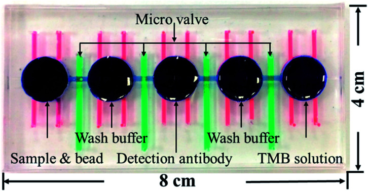
1. Introduction
Statistics from the World Health Organization have shown that the number of deaths due to cancer in 2011 exceeded the number of deaths due to heart disease or stroke1,2 and that cancer will be the main cause of death worldwide in the next few decades.3,4 In Taiwan, malignant tumors have been the leading cause of death in recent years and the number of deaths due to oral cancer is ranked fifth among the different types of cancers.5 Even though current medical technology has tremendously improved, 40–50% of oral cancer patients still die within 5 years of being diagnosed.6,7 The main cause of this is that most patients are diagnosed at the late stage of cancer; this means that the cancer could have already metastasized or the tumor could have expanded, which implies some degree of risk for subsequent surgery and providing treatment while the therapeutic effect is limited. The diagnosis of oral cancers is dependent on questions asked by physicians during diagnosis such as whether patients have any family history of the disease and whether patients have a habit of chewing betel nuts, smoking, or alcohol use or through physicians' observations of whether patients have white plaque, oral fibrosis, hyperplasia, masses, ulcers, etc., and whether tissue biopsy has been performed. However, these methods may result in delayed diagnosis if patients at their early stages of cancer show no signs or if their signs are difficult to observe.8,9 Therefore, in recent years, many scholars have searched for biomarkers for the early diagnosis of cancers. Among these biomarkers, autoantibodies have stability and high specificity and have mature auxiliary reagents available. Therefore, many autoantibodies have already been used as biomarkers for the detection of various cancers such as colorectal cancer,10 breast cancer,11–13 ovarian cancer,14 lung cancer,15,16 and liver cancer.17,18 In addition, serum or salivary autoantibodies can be used as biomarkers for the early detection of oral cancer.19,20 Our research team screened and selected four potential autoantibodies from saliva samples in 2014 (ref. 21) for using them as biomarkers for the early detection of oral cancer. Other studies have shown that the concentration of anti-p53 in saliva is a potential biomarker for screening oral cavity squamous cell carcinoma.8,22,23 Among them, anti-p53 has the highest sensitivity. Therefore, this study used anti-p53 in the saliva as the target for detection; among body fluid samples, salivary samples can be non-invasively collected.
An immunoassay is an important biological analysis tool. The principle is to use the specificity between antibodies and antigens to detect the concentration of specific substances in samples. Commonly used immunoassays include fluorescence immunoassay,24 chemiluminescence immunoassay,25 and enzyme-linked immunosorbent assay.26 Even though these immunoassays are well developed, the analysis still takes several hours and analysis results may be affected by human factors; therefore, experienced personnel are required for performing them. In recent years, micro total analysis systems have been employed in multiple analytical domains. This technology uses microelectromechanical technology to combine microdevices such as micropumps, micromixers, and microvalves into a chip. These microdevices are used to manipulate microfluids to perform biological and biochemical analysis.27,28 This chip has advantages such as rapid reactions, portability, improved sensitivity, and the low quantity of reagents used. In addition, automation can be achieved through the combination of software and hardware.29
Microbeads are commonly used in immunoassays. The use of a combination of microbead- or carbon nanotube-based immunoassay and electrochemiluminescence for detecting cancer biomarkers has been demonstrated.30,31 Chen et al. proposed single microbead-anchored immunoassay, which allowed the detection of multiple antigens.32 Pre-labeled fluorescent magnetic beads are widely used in multiplex immunoassays.33 In addition, the combination of bead-based immunoassay with a microfluidic system has advantages of rapid detection and high integration.34 Choi et al. (2002) published a study on magnetic immunoassay in microfluidic chips.35 They proved that this magnetic bead-based biochemical detection system can use low amounts of reagents for analyzing proteins. This chip fixes magnetic beads for reagents and samples to pass through, and magnetic beads are used to capture corresponding antigens and antibodies. If magnetic beads can be mixed within the fluid, the effect of mixing would be even better. In addition, there are studies using pneumatic microdevices to allow magnetic beads and reagents to be transmitted, mixed, and washed.24,25 However, in this design, most mixing reactions occur in one reaction well, and this may result in contamination in the reaction well due to the adsorption of the analyte on the surface of the reaction well during incubation. Some research teams used immiscible oil–water liquids to separate each reaction well and used magnets to control the movement of magnetic beads and mixing with samples; this method does not require the manipulation of liquids for analysis.26,36,37 The advantage of this method is that it does not require valves to separate reaction wells and prevent contamination. However, the effects of mixing of reagents and magnetic beads are not as good.
In the present study, microvalves, micromixers in combination with solenoid valves, X-Y stages, and magnets were used to develop an automated detection platform. In this platform, magnetic bead-based immunoassays are used to analyze and quantitate the concentrations of anti-p53 autoantibodies in saliva. The chip uses microvalves to separate every reaction well, which can avoid the cross-contamination of reagents between adjacent wells. The use of multiple reaction wells and moving magnetic beads decreases the non-specific adsorption of proteins and antibodies and reduces wash steps, thereby increasing the detection accuracy. In addition, the combination of micromixers to achieve high efficiency mixing can decrease the total detection time. We hope that this chip can help oral cancer patients be diagnosed early and to provide early treatment, thereby improving their survival rates and lowering the use of medical resources.
2. Materials and methods
2.1. Chip design and fabrication
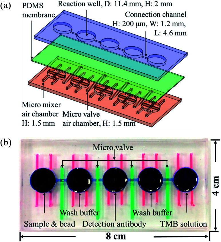
Fig. 1(a) shows the magnified view of the microfluidics chip, whose structure mainly consists of three layers. These layers are the reaction wells and channel layers in the upper. Five reaction wells of equal size were designed for the chip, which was filled with samples, wash buffer, detection antibodies, and color-developing agents (enzyme substrate). The diameter of each reaction well was 11.4 mm and the height 2 mm. Each well was filled with approximately 200 μL of the reagent, and the length and width of the channels connecting the reaction wells were 4.6 mm and 0.2 mm, respectively. The bottom layer contained four pneumatic microvalves' and five pneumatic micromixers' air chambers, and their locations corresponded to the center of the microchannels and reaction wells in the upper layer. There was a polydimethylsiloxane (PDMS) membrane of 100 μm thickness between the upper and lower layers. When pressure was exerted in air chambers below the membrane, pneumatic microvalves and micromixer were driven by membrane uplifting.
Fig. 1. (a) Exploded view of the microfluidic chip. The chips are made up of three PDMS layers: the top layer contains the reaction wells and microchannels, the middle layer is a 100 μm membrane, and the bottom layer contains the pneumatic mixers' and microvalves' air chambers. (b) Shows the photograph of the chip. Red ink denotes the mixer, green ink the valves, and blue ink the reaction wells and channels. The size of the chip is 8 × 4 cm.
The fabrication process of the chip included using the drawing software (Solidworks, Dassault Systèmes SOLIDWORKS Corp., USA) to design the master mold of the chip. This was followed by using a computer numerical controlled CNC (EGX-400, Roland Inc., Japan) for processing two pieces of polymethylmethacrylate (PMMA) boards to produce the master molds of the upper and lower layers. Then, PDMS was formulated (A : B ratio of 10 : 1, Sil-More, Taiwan), homogeneously mixed, and poured into the master mold. Vacuum was used to remove bubbles in PDMS, and the molds were then transferred to an oven for baking at 80 °C for 2 h. After solidification, the molds were removed. For the production of the membrane for the middle layer, 5 g of PDMS was poured onto a polished PMMA board (10 × 10 cm) and a spin coater (MS-A100, MIKASA, Japan) was used in two stages with parameters of 500 rpm for 10 s and 1000 rpm for 10 s to create a membrane with a specific thickness of approximately 100 μm. This was then placed in an oven for baking at 80 °C for 1 h for solidification. After the structure of each layer formed, a 0.5 mm diameter biopsy punch (ProSciTech, Australia) was used to punch holes on the chip to create inlets for air to enter. A plasma cleaner (PDC-001, Harrick Plasma, USA) was used to adhere the various layers. The size of the chip was 8 × 4 cm, as shown in Fig. 1(b).
2.2. Design and working principle of the pneumatic micromixer and microvalves
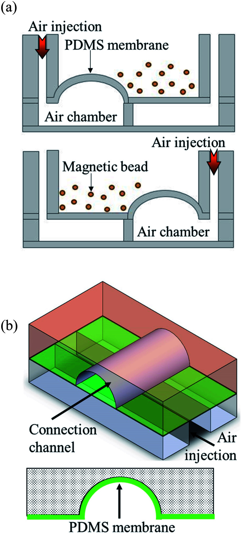
Pneumatic micromixers were used to increase the incubation efficiency of the immunoassay, and the schematic diagram is shown in Fig. 2(a). The working principle of the micromixer is to divide the air chambers below the reaction well into four zones, and the air chamber above each zone contained a membrane made of elastic PDMS. When compressed air at certain pressures was injected into the air chamber, the membrane was lifted up. When the four zones of membranes were actuated with sequential time differences, a vortex-like disturbance was created in the fluid inside the reaction well above the air chamber and a mixing effect was achieved. Magnetic bead-based immunoassays were used in this study and the beads were moved and passed through five reaction chambers. Therefore, microchannels connected the reaction wells to each other to transport magnetic beads. Furthermore, to avoid contamination caused by the reagents or samples in adjacent reaction well while operating the micromixer, pneumatic valves were designed in channels to prevent the interconnection of fluids between reaction wells. The method proposed by the Quake team38 was used as reference for designing these valves. The channels were designed in an arc shape so that when the membrane rose, it completely adhered to the channels, and the fluids were separated without any leakage. Fig. 2(b) shows the schematic diagram of this design.
Fig. 2. Schematic diagram of the operating principle of the micromixers and valves. (a) Compressed air is injected into the four independent air chambers below the micromixers. The membrane on the top of the air chamber was pushed by the air and rise up. When compressed air was sequentially driven into the four chambers, a vortex-like disturbance was created in the liquid above the membrane. (b) When the compressed air was injected into the air channel of the microvalves, the membrane above the air channels rose and obstructed the channels. Only arc-shaped channels allowed the valves to be fully closed.
2.3. Operation procedure of the autoantibody immunoassay chip
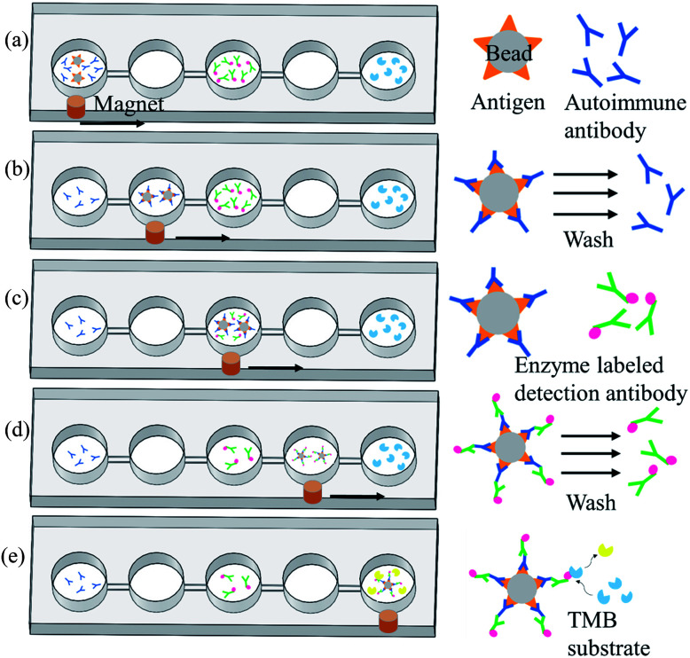
Magnetic bead-based immunoassay was used for the detection of autoantibodies, and the concept of moving magnetic beads instead of transporting fluids was used to complete the entire analysis. Fig. 3 shows the operation procedure of the chip. First, samples and reagents required for the immunoassay were individually loaded in five reaction wells in the chip: 200 μL of mouse anti-p53 antibody standard solution or patient's samples and 5 μL of magnetic beads coated with p53 antigen (5 × 10⁷ beads per mL) in the first reaction well, 200 μL of phosphate buffered saline (PBS) wash buffer in the second and fourth reaction wells, 200 μL of 20 ng mL−1 anti-mouse IgG-conjugated horse radish peroxidase (HRP) or biotinylated anti-human IgA with streptavidin-HRP in the third reaction well, and 200 μL of color-developing agent in the fifth reaction well. The mouse anti-p53 antibody and anti-mouse IgG were used to set up the proposed assay platform. For anti-p53 autoantibody detection in human saliva, anti-human IgA was used. Following that, the pneumatic micromixer below the first reaction well was started to facilitate the fluid and magnetic beads mix for 20 min. The p53 antigen on the magnetic beads was used to capture anti-p53 in the samples or specimen. After completing this step, an external magnet was used to collect the magnetic beads for 1 min. Then, these beads were moved to the next reaction well at a speed of 133 μm s−1. After the magnetic beads were moved to the second reaction well, the external magnet was removed and the micromixer below the well was activated for 1 min to promote mixing of the magnetic bead and PBS wash buffer. This was to remove excess nonspecifically bound substances. After washing was completed, the magnetic beads were collected again below the reaction well for 1 min. After collecting the magnetic beads, the beads were moved to the next reaction well. In the third reaction well, the magnetic beads that captured anti-p53 and detection antibodies containing HRP were mixed for 20 min. After mixing was completed, the steps of the collection and movement of magnetic beads were repeated. The operation procedure of the magnetic beads in the fourth reaction well was the same as that in the second reaction well: to remove the excess detection antibody. In the fifth reaction well, HRP-containing magnetic beads were mixed with an enzyme substrate (TMB) for 15 min. The color intensity is related to the concentration of autoantibodies captured. Lastly, the magnetic beads were attracted at the side of the reaction wells, and a Pipetman was used to aspirate 100 μL of the samples into a microtube and 50 μL of the stop solution was added. Finally, 100 μL of the sample was pipetted into a 96-well plate, and a microplate reader (SpectraMax M5, Molecular Devices, Sunnyvale, USA) was used to read the optical density at 450 nm. The reaction product has an absorbance peak at 450 nm; when light at 450 nm passes through the sample, some of it is absorbed by sample and the transmitted part can be measured by an optical sensor. The amount of transmitted signal is related to the target protein.
Fig. 3. Operation procedures for the detection of autoantibody of the chip. (a) Magnetic beads with p53 antigen capture the autoantibodies from samples. (b) A magnet was used to move the magnetic beads to the next reaction well for washing so that unbound substances can be washed off. (c) All magnetic beads containing autoantibodies to be tested were allowed to bind to detection antibodies with enzymes at the ends. (d) A magnet was used to move the magnetic beads into the next reaction well to wash excess detection antibodies. (e) Magnetic beads with detection antibodies were allowed to react with the enzyme substrate. The supernatant was aspirated to microplates, and a stop solution was added. A microplate reader was used to read values.
2.4. Reagent, sample, and experimental setup
The magnetic beads (2.8 μm, Dynabeads M-270 Carboxylic Acid, Thermo Fisher Scientific) used for the immunoassay were obtained from Invitrogen. Before the immunoassay, the p53 antigen (Recombinant Human His6-p53, Boston Biochem) was coated on the surface of the magnetic beads following the manufacturer's protocol. To quench the non-reacted activated carboxylic acid groups, the coated beads were incubated in a wash buffer for 15 min, which contains 50 mM Tris, 0.1% bovine serum albumin (BSA), and 0.1% Tween-20 in a solution at pH 7.4. We experimentally confirmed that the microbeads were fully coated by the antigen at maximum binding capacity (ESI Fig. S1†). The standard solutions for the sample were prepared by dissolving mouse anti-p53 antibodies (SC-126, Santa Cruz Biotechnology) in PBS buffer solution and were serially diluted into concentrations of 4 μg mL−1, 400 ng mL−1, 40 ng mL−1, and 4 ng mL−1. PBS, BSA, and 2 N H2SO4 stop solution were purchased from Sigma-Aldrich. Anti-mouse IgG-conjugated HRP (1 mg mL−1, NEF822001EA, PerkinElmer) was purchased from PerkinElmer. The color-developing agent tetramethylbenzidine was purchased from Clinical Science Products, Inc. Because the purified human anti-p53 autoantibody is difficult to obtain, the mouse anti-p53 antibody and anti-mouse IgG-conjugated HRP were used to set up the platform. On the other hand, because IgA is the main class of antibodies present in human saliva (more than 300 times the level of IgG),39,40 the secondary antibody of goat biotin-conjugated anti-human IgA (205008, AbD Serotec, USA) and streptavidin-HRP (BioLegend, USA) were used for detecting the human anti-p53 autoantibody. The saliva samples of three patients containing high, medium, and low anti-p53 autoantibody concentrations, respectively, were used. All volunteers underwent oral mucosal screening test. The individuals with oral cancer were biopsy proven and underwent routine checkups according to the standard protocol. This research followed the tenets of the Declaration of Helsinki, and all patients signed an informed consent form approved by the Institutional Review Board of Chi-Mei Medical Center (IRB number: 10012-L02) before participating in the study and permitting the use of saliva samples. During the experiment, these samples were diluted 25 times in PBS. The collected saliva samples were first centrifuged at 3000 × g for 15 min at 4 °C, and protease inhibitor cocktail (2 μL mL−1, Sigma-Aldrich) was added to the supernatant. Then, the samples were stored at −80 °C in a freezer. For detailed sample processing procedures, please see ref. 21. The experimental setup is shown in ESI Fig. S2.† LabVIEW (National Instruments, USA) was used to control the solenoid valve and the X-Y stage (X-LSM100A, Zaber, USA). A DAQ (USB-6001, National Instruments, USA) device was used to transmit signals to the solenoid valve. The air compressor (JW-2525N, Jun-wei, Taiwan), solenoid valve (S070M-SBG-32, SMC, Japan), and chip were connected and the micromixer and microvalve were driven by opening and closing the solenoid valve. An X-Y stage that can be controlled by a program was located below the chip. A strong magnet was placed above the stage to adsorb magnetic beads in the chip, and the magnet was obtained from dismantling hard disks. The chip was placed on a platform with an adjustable z-axis, and the distance between the adjustable chip and the strong magnet was 0.5 mm. The closer the distance between the two, the better, ensuring that there is sufficient magnetic force to attract the magnetic beads. The movement speed, position, and dwell time of the strong magnet were used for the collection and movement of the magnetic beads.
3. Results and discussion
3.1. Micromixer and microvalve parameter optimization
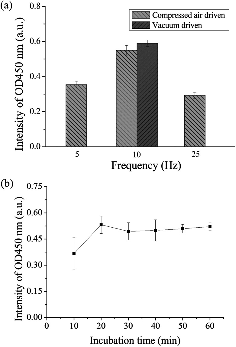
If there was a high efficient mixer in the chip, the chances of contact between the antigen and antibody can be increased, which can shorten the detection time. Therefore, the operation frequency of the micromixer was first optimized. Binding between the autoantibodies and detection antibodies by placing in the micromixer was performed to evaluate the optimal operation frequency for the pneumatic micromixer. The remaining immunoassay steps were performed in a 1.5 mL microtube. Anti-p53 autoantibodies with a concentration of 4 μg mL−1 were used for the test. The concentration and volume of the remaining reagents were as described in Section 2.3. The three mixing frequencies used were 5, 10, and 25 Hz, and mixing was performed for 30 min. Finally, color development results were compared to evaluate the optimal mixing frequency. Each experiment was performed in triplicate. From Fig. 4(a), we can observe that the final OD value of a frequency of 10 Hz was the highest, which shows that there was more binding of detection antibody on the magnetic beads during mixing. Therefore, the operating frequencies of all micromixers on the chip were set at 10 Hz. A slower operating frequency (below 10 Hz) results in poor mixing results, while a faster operating frequency (25 Hz) results in the deformation speed of the PDMS membrane being unable to match the discharge frequency of air pressure and result in no further increase in the mixing efficiency.41 In addition, the study compared the efficiency of positive pressure-driven mixers and negative pressure-driven mixers under an operation frequency of 10 Hz. From these results, we can observe that there were no great differences in the mixing efficiency between positive or negative pressure-driven mixers. In the experimental setup, we selected positive pressure to drive the micromixer for convenience, which is consistent with the driving method for the microvalves. In addition, the incubation time between the antigen and the antibody was optimized in the micromixer. We used the immunoassay step where the antigen on the magnetic bead captured the antibody for evaluation. Magnetic beads coated with p53 and the standard sample of anti-p53 with a concentration of 20 ng mL−1 were added into the micromixer in the chip and mixed for 10, 20, 30, 40, 50, and 60 min. All subsequent steps were performed in a 1.5 mL microtube, and the concentrations and volumes of the remaining reagents used were the same as those described in Section 2.3. Finally, color development results were used to evaluate the mixing time required for mixing the antigen and the antibody in the chip. The evaluation of each mixing time was performed using chips and was repeated in triplicate. The results are shown in Fig. 4(b). The value approached saturation after 20 min. This shows that after 20 min, the antigens on the magnetic beads fully bound to the antibodies, and even if the incubation time was further increased, there was no increase in signal intensity. Therefore, the sample incubation time in the present study was set to 20 min. In addition, when the mixer in the chip is in operation, the microvalves in the adjacent wells should remain closed to prevent reagent contamination between the reaction wells. We used red dyes added into the microchannels and gradually increased the air pressure in the pneumatic microvalves to perform leakage testing. The experiment results showed that when the air pressure reached 35 kPa, the valves were shut tightly to prevent adjacent fluids from flowing (ESI Fig. S3†). However, we also observed that when the valves were actuated greater than 50 kPa for more than 10 min, air bubbles were produced in the microchannel, which would obstruct the moving magnetic beads. The membranes may have a certain permeability; therefore, under conditions where the air pressure duration is long and pressure is too high, the gas passed through the membrane and produced bubbles. Therefore, microchannels should not be designed too high to avoid having to use an overly high air pressure to open and close the valves. In addition, the channel width was designed to be 200 μm to provide a sufficient channel cross-section for bead movement.
Fig. 4. (a) Optimization results of the operating frequency of the micromixer. Different frequencies were used to mix the detection antibody and the anti-p53 coated magnetic beads. From the coloration signal we can see that the signal was the highest at a frequency of 10 Hz. In addition, there were no differences in mixing efficiency when positive pressure or negative air pressure was used. (b) Optimization of incubation time between antigen and antibody. The chip was used to carry out different mixing times between anti-p53 and p53 coated magnetic beads. The OD value approaches saturation after 20 minutes.
In addition, we have tested magnetic beads having larger size (approximately 50 μm in diameter, GE Healthcare). It was observed that the mixing behavior was not as vigorous as the 2.8 μm beads used presently at the same driving frequency. Even the driving pressure and frequency were increased; some of the large beads precipitated to the bottom of the micromixer. This may cause the low mixing efficiency during sample incubation. Nevertheless, a large bead would be clogged in the microchannel between two reaction wells when moving the bead. We suggest that suitable sizes of a microbead should range from 1 μm to 5 μm in this platform.
3.2. Antifouling coating of PDMS
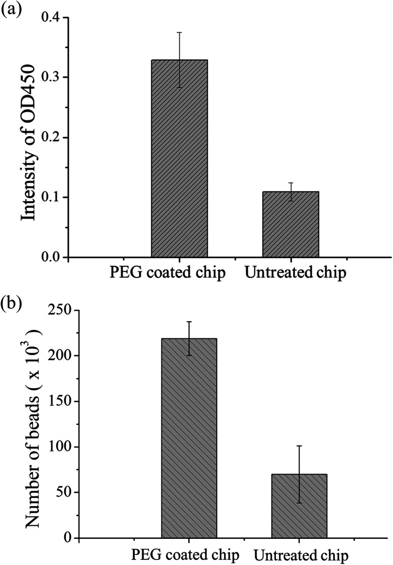
The material of the chip was PDMS. Although this material has high transparency and biocompatibility, the easy adhesion of proteins is a major problem in protein study application. During the present study, we found that some magnetic beads adhered to the chip surface due to some proteins on the bead surface. A decrease in the number of beads results in lower OD values, and this results in the inability to detect samples with low concentrations. Therefore, PEG-silane coating was used on PDMS as a protein antifouling agent. The detailed method is described in ref. 42. The experimental design was to compare PDMS chips with PEG modification to chips without modification for magnetic bead-based immunoassay. In these chips, 5 μL of equivalent number of p53-coated magnetic beads, 0.4 μg mL−1 of anti-p53 antibodies, and 20 ng mL−1 of detection antibodies were added. After the immunoassay ended, OD values were determined and the magnetic beads in the last reaction well were counted using flow cytometry. Each experiment used three chips and was repeated thrice. Fig. 5(a) shows the comparison of the OD values. The experiment results showed that the signal from the PEG-modified chips was higher than that of the non-modified chips. This may be due to the modified chip being more difficult for proteins and magnetic beads to adhere to. In addition, the number of magnetic beads was counted in the last well using flow cytometry, and the results are shown in Fig. 5(b). From the results, the number of beads lost was improved by a PEG-modified PDMS chip (from approximately 70 000 to 220 000), which provided evidence of signal increment. In addition, we found that approximately 15% of the magnetic beads adhered to each other in the modified chips, while 8% of the magnetic beads adhered to each other in the unmodified chips (ESI Fig. S4†). This may be due to some PEG from the modified PDMS dissolving in the solution, resulting in more mutual adhesion of magnetic beads. The experiment shows that PEG modification can decrease protein adsorption. Therefore, all chips used in the present study underwent PEG modification. Besides the adsorption of magnetic beads on the PDMS surface, external magnets are a cause of bead loss. If the position of the magnet does not correspond well with the position of the chip, this results in insufficient magnetic force and in large number of bead loss. The magnet was placed approximately 0.5 mm below the chip to ensure that there was sufficient magnetic force to attract and collect the magnetic beads. Every time incubation was completed, the magnet was placed below the mixer for 60 s so that it could collect the dispersed magnetic beads. During movement of magnetic beads, a slow speed of 133 μm s−1 was used to ensure that the magnetic beads are attracted to the external magnetic field (ESI Movie†).
Fig. 5. (a) Immunoassay results of unmodified PDMS chip and PEG-modified PDMS chip. The signal intensity of the PEG-modified chip was higher because PDMS itself can adsorb proteins and thus p53 coated magnetic beads and the analyte to be tested will both be adsorbed by PDMS. (b) Flow cytometry was used to compare the unmodified chip and the PEG-modified chip by counting the number of beads after the immunoassay was completed.
3.3. Detection limit of anti-p53 autoantibodies and detection in saliva samples from patients
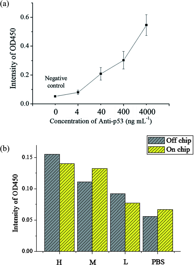
The evaluation of the detection limit was performed using standard solutions of anti-p53 autoantibodies that were 10 × diluted serially from 4 μg mL−1 to 4 ng mL−1. The experiment procedures are described in Section 2.3. For the negative control, 200 μL of 1% BSA was used to as a substitute for an equal volume of anti-p53 samples. The mean and standard deviation of values was obtained from the use of three chips that were used thrice. The results are shown in Fig. 6(a). As anti-p53 concentrations decreased, corresponding OD values after developed also decreased. The limit of detection (LOD) was calculated using the 3σS method,43 where σ is the standard deviation of the negative control and S is the slope defined as Δconcentration/Δintensity. S was calculated using concentrations from 0 to 0.004 μg mL−1 [0.004 μg mL−1/(0.079 − 0.052) OD = 0.145 μg mL−1 OD−1]. The LOD was calculated as follows: 3 × 0.0084 × 0.145 μg mL−1 = 3.654 ng mL−1. The data also showed that the signal at 4 ng mL−1 was detected in the experiment. Compared to plate-based ELISA with the same reagents, the linear dynamic range of plate-based ELISA was less than that of the proposed microfluidic chip (ESI Fig. S5†). This may due to the larger surface area of microbeads, which can immobilize larger amounts of the p53 antigen for autoantibody capture. In addition, the detection limit of plate-based ELISA was lower than that of the proposed system by more than one order. This may due to bead loss during the assay in the chip. In addition, the target autoantibody detected in a spiked sample matrix can evaluate interferences caused in a real situation. However, the purified human anti-p53 autoantibody is difficult to obtain. We used the mouse anti-p53 antibody and anti-mouse IgG to set up the detection platform as well as human saliva and anti-human IgA to determine the feasibility of the real sample detection in the platform. The saliva samples of three patients with known anti-p53 relative concentrations (high, medium, and low) were tested to see if the chip can distinguish the relative concentrations of anti-p53 autoantibodies. The level of anti-p53 autoantibodies in the saliva sample were determined using the Bio-Plex 200 system and Bio-Plex Manager software version 4.2 (Bio-Rad Laboratories), which showed the relative fluorescent intensity of the target analyte on the microbead. Simultaneously, results from the microtube method using the same reaction conditions were used as a comparison, and the negative control was an equivalent volume of 1% BSA. The results [as shown in Fig. 6(b)] from the microfluidic chip were consistent with the results obtained using microtubes. However, the signal detected from the patient with a medium level of autoantibodies was higher. As samples obtained from patients only allow for one test, if more tests were performed to obtain an average value, the signal should approach the results using microtubes. However, in general, the results confirm that the proposed device can be used for detecting autoantibodies in a saliva sample, whereas most current studies could only detect anti-p53 antibodies in serum samples. The signal can be improved using the following methods: the first method is to increase the incubation time between magnetic beads and the enzyme substrate; however, this will result in some test time being sacrificed. The second is to modify the movement path of the X-Y stage so that when the magnetic beads are being collected, the scanning route can be used or collection can be repeated to decrease the loss of magnetic beads. The third is to change the developing substrate into a fluorescent substrate that can further increase detection sensitivity. In addition, we have evaluated21 the cross-reactivity of assay in saliva samples. The antibodies were detected in saliva samples using antigen-conjugated beads in a single antigen-coated bead (singleplex) and five antigen-coated beads (multiplex). The experimental results revealed that the assay demonstrated limited cross-reactivity between the five autoantibodies in the saliva sample. Furthermore, antibodies commonly co-existing with anti-p53 IgA, such as IgM and IgG, may influence the results of the assay. Because IgA is the dominant antibody class rather than IgG or IgM in saliva samples (more than 300 times the level of IgG)39,40 and the secondary antibody, anti-human IgA we used has high specificity to human IgA, we expected that IgG and IgM in saliva would only have a slight influence in detecting IgA.
Fig. 6. (a) Anti-p53 autoantibody immunoassay results. As anti-p53 concentration increases, the signal also increases. The detection limit of the chip is about 4 ng mL−1. The entire test requires about 60 minutes. (b) Immunoassay results of saliva samples from oral cancer patients. The results confirm that the detection performance of the device is broadly comparable to that of the microtube test. This proves that this chip can be used for detection in patient samples.
4. Conclusion
We developed an automated microfluidics system using LabVIEW to integrate the movement of the XY stage, the actuation of micromixers, and the opening and closing of microvalves for the automated immunoassay of anti-53 in saliva. The time for the immunoassay decreased from 3 h in conventional immunoassays to only approximately 60 min using the proposed platform. The detection limit of this microfluidic chip is approximately 4 ng mL−1, and relative concentrations can be detected from saliva. We hope that further optimization can be conducted such as the optimization of the concentration of the detection antibody used so that the contamination of excess detection antibody in the reaction well can be minimized. For the manipulation route of external magnets, many types of movement routes can be attempted, and repeated movement between reaction wells can be performed to decrease the amount of residual magnetic beads. In addition, the chip surface can be modified with other materials that prevent protein adhesion so that the detection signal intensity can be strengthened and the detection limit can be decreased.
Conflicts of interest
There are no conflicts to declare.
Supplementary Material
Acknowledgments
The authors would like to thank the Ministry of Science and Technology of Taiwan and the Chang Gung Memorial Hospital for their funding support (105-2221-E-182-036-MY3, CMRPD2G0261, BMRPC01).
Electronic supplementary information (ESI) available. See DOI: 10.1039/c7ra13734f
References
- Ferlay J. Soerjomataram I. Dikshit R. Eser S. Mathers C. Rebelo M. Parkin D. M. Forman D. Bray F. Int. J. Cancer. 2015;136:E359–E386. doi: 10.1002/ijc.29210. [DOI] [PubMed] [Google Scholar]
- Siegel R. Naishadham D. Jemal A. Ca-Cancer J. Clin. 2013;63:11–30. doi: 10.3322/caac.21166. [DOI] [PubMed] [Google Scholar]
- Ferlay J. Shin H. R. Bray F. Forman D. Mathers C. Parkin D. M. Int. J. Cancer. 2010;127:2893–2917. doi: 10.1002/ijc.25516. [DOI] [PubMed] [Google Scholar]
- Bray F. Jemal A. Grey N. Ferlay J. Forman D. Lancet Oncol. 2012;13:790–801. doi: 10.1016/S1470-2045(12)70211-5. [DOI] [PubMed] [Google Scholar]
- Chang K.-P. Wu C.-C. Fang K.-H. Tsai C.-Y. Chang Y.-L. Liu S.-C. Kao H.-K. Oral Oncol. 2013;49:802–807. doi: 10.1016/j.oraloncology.2013.05.006. [DOI] [PubMed] [Google Scholar]
- Liu S. Y. Lu C. L. Chiou C. T. Yen C. Y. Liaw G. A. Chen Y. C. Liu Y. C. Chiang W. F. Oral Oncol. 2010;46:276–282. doi: 10.1016/j.oraloncology.2010.01.008. [DOI] [PubMed] [Google Scholar]
- Chen Y. J. Chang J. T. C. Liao C. T. Wang H. M. Yen T. C. Chiu C. C. Lu Y. C. Li H. F. Cheng A. J. Cancer Sci. 2008;99:1507–1514. doi: 10.1111/j.1349-7006.2008.00863.x. [DOI] [PMC free article] [PubMed] [Google Scholar]
- Warnakulasuriya S. Reibel J. Bouquot J. Dabelsteen E. J. Oral Pathol. Med. 2008;37:127–133. doi: 10.1111/j.1600-0714.2007.00584.x. [DOI] [PubMed] [Google Scholar]
- Neville B. W. Day T. A. Ca-Cancer J. Clin. 2002;52:195–215. doi: 10.3322/canjclin.52.4.195. [DOI] [PubMed] [Google Scholar]
- Chen J. S. Kuo Y. B. Chou Y. P. Chan C. C. Fan C. W. Chen K. T. Huang Y. S. Chan E. C. Clin. Chim. Acta. 2011;412:1417–1422. doi: 10.1016/j.cca.2011.04.020. [DOI] [PubMed] [Google Scholar]
- Desmetz C. Bascoul-Mollevi C. Rochaix P. Lamy P. J. Kramar A. Rouanet P. Maudelonde T. Mangé A. Solassol J. Clin. Cancer Res. 2009;15:4733–4741. doi: 10.1158/1078-0432.CCR-08-3307. [DOI] [PubMed] [Google Scholar]
- Anderson K. S. Sibani S. Wallstrom G. Mendoza E. A. Raphael J. Hainsworth E. Montor W. R. Wong J. Park J. G. Lokko N. Logvinenko T. Ramachandran N. Godwin A. K. Marks J. Engstrom P. LaBaer J. J. Proteome Res. 2011;10:85–96. doi: 10.1021/pr100686b. [DOI] [PMC free article] [PubMed] [Google Scholar]
- Sun Y. Zhang R. Wang M. Zhang Y. Qi J. Li J. Cancer Epidemiol., Biomarkers Prev. 2012;21:2043–2047. doi: 10.1158/1055-9965.EPI-12-0498. [DOI] [PubMed] [Google Scholar]
- Karabudak A. A. Hafner J. Shetty V. Chen S. Secord A. A. Morse M. A. Philip R. J. Cancer Res. Clin. Oncol. 2013;139:1757–1770. doi: 10.1007/s00432-013-1501-6. [DOI] [PMC free article] [PubMed] [Google Scholar]
- Dai N. Cao X. J. Li M. X. Qing Y. Liao L. Lu X. F. Zhang S. H. Li Z. Yang Y. X. Wang D. PLoS One. 2013;8:e58001. doi: 10.1371/journal.pone.0058001. [DOI] [PMC free article] [PubMed] [Google Scholar]
- Rom W. N. Goldberg J. D. Addrizzo-Harris D. Watson H. N. Khilkin M. Greenberg A. K. Naidich D. P. Crawford B. Eylers E. Liu D. Tan E. M. BMC Cancer. 2010;10:234. doi: 10.1186/1471-2407-10-234. [DOI] [PMC free article] [PubMed] [Google Scholar]
- Shao Q. Ren P. Li Y. Peng B. Dai L. Lei N. Yao W. Zhao G. Li L. Zhang J. Int. J. Oncol. 2012;41:1061–1067. doi: 10.3892/ijo.2012.1515. [DOI] [PMC free article] [PubMed] [Google Scholar]
- Liu H. Zhang J. Wang S. Pang Z. Wang Z. Zhou W. Wu M. Cancer Epidemiol. 2012;36:82–88. doi: 10.1016/j.canep.2011.04.001. [DOI] [PubMed] [Google Scholar]
- Kaur J. Srivastava A. Ralhan R. Int. J. Cancer. 1997;74:609–613. doi: 10.1002/(SICI)1097-0215(19971219)74:6<609::AID-IJC9>3.0.CO;2-Y. [DOI] [PubMed] [Google Scholar]
- Ralhan R. Nath N. Agarwal S. Mathur M. Wasylyk B. Shukla N. K. Clin. Cancer Res. 1998;4:2147–2152. [PubMed] [Google Scholar]
- Wu C. C. Chang Y. T. Chang K. P. Liu Y. L. Liu H. P. Lee I. L. Yu J. S. Chiang W. F. Cancer Epidemiol., Biomarkers Prev. 2014;23:1569–1578. doi: 10.1158/1055-9965.EPI-13-1269. [DOI] [PubMed] [Google Scholar]
- Tavassoli M. Brunel N. Maher R. Johnson N. W. Soussi T. Int. J. Cancer. 1998;78:390–391. doi: 10.1002/(SICI)1097-0215(19981029)78:3<390::AID-IJC23>3.0.CO;2-9. [DOI] [PubMed] [Google Scholar]
- Warnakulasuriya S. Soussi T. Maher R. Johnson N. Tavassoli M. J. Pathol. 2000;192:52–57. doi: 10.1002/1096-9896(2000)9999:9999<::AID-PATH669>3.0.CO;2-C. [DOI] [PubMed] [Google Scholar]
- Lee Y. F. Lien K. Y. Lei H. Y. Lee G. B. Biosens. Bioelectron. 2009;25:745–752. doi: 10.1016/j.bios.2009.08.020. [DOI] [PMC free article] [PubMed] [Google Scholar]
- Chang K. W. Li J. Yang C. H. Shiesh S. C. Lee G. B. Biosens. Bioelectron. 2015;68:397–403. doi: 10.1016/j.bios.2015.01.027. [DOI] [PubMed] [Google Scholar]
- Adel Ahmed H. Azzazy H. M. E. Biosens. Bioelectron. 2013;49:478–484. doi: 10.1016/j.bios.2013.05.058. [DOI] [PubMed] [Google Scholar]
- Auroux P. A. Iossifidis D. Reyes D. R. Manz A. Anal. Chem. 2002;74:2637–2652. doi: 10.1021/ac020239t. [DOI] [PubMed] [Google Scholar]
- Vilkner T. Janasek D. Manz A. Anal. Chem. 2004;76:3373–3386. doi: 10.1021/ac040063q. [DOI] [PubMed] [Google Scholar]
- Li J. Chang K. W. Wang C. H. Yang C. H. Shiesh S. C. Lee G. B. Biosens. Bioelectron. 2016;79:887–893. doi: 10.1016/j.bios.2016.01.029. [DOI] [PubMed] [Google Scholar]
- Valenti G. Rampazzo E. Biavardi E. Villani E. Fracasso G. Marcaccio M. Bertani F. Ramarli D. Dalcanale E. Paolucci F. Prodi L. Faraday Discuss. 2015;185:299–309. doi: 10.1039/C5FD00096C. [DOI] [PubMed] [Google Scholar]
- Sardesai N. P. Barron J. C. Rusling J. F. Anal. Chem. 2011;83:6698–6703. doi: 10.1021/ac201292q. [DOI] [PMC free article] [PubMed] [Google Scholar]
- Chen D. Zhang X. Zhu L. Liu C. Li Z. Chem.–Asian J. 2017;12:2874. doi: 10.1002/asia.201701396. [DOI] [PubMed] [Google Scholar]
- Ravindran R. Khan I. H. Krishnan V. V. Ziman M. Kendall L. V. Frasier J. M. Bates R. Griffey S. M. Fahey J. R. Luciw P. A. J. Immunol. Methods. 2010;363:51–59. doi: 10.1016/j.jim.2010.10.003. [DOI] [PubMed] [Google Scholar]
- Cui X. Liu Y. Hu D. Qian W. Tin C. Sun D. Chen W. Lam R. H. W. Lab Chip. 2018;18:522–531. doi: 10.1039/C7LC01183K. [DOI] [PubMed] [Google Scholar]
- Choi J. W. Oh K. W. Thomas J. H. Heineman W. R. Halsall H. B. Nevin J. H. Helmicki A. J. Henderson H. T. Ahn C. H. Lab Chip. 2002;2:27–30. doi: 10.1039/B107540N. [DOI] [PubMed] [Google Scholar]
- Kim J. A. Kim M. Kang S. M. Lim K. T. Kim T. S. Kang J. Y. Biosens. Bioelectron. 2015;67:724–732. doi: 10.1016/j.bios.2014.10.042. [DOI] [PubMed] [Google Scholar]
- Berry S. M. MacCoux L. J. Beebe D. J. Anal. Chem. 2012;84:5518–5523. doi: 10.1021/ac300085m. [DOI] [PubMed] [Google Scholar]
- Unger M. A. Chou H. P. Thorsen T. Scherer A. Quake S. R. Science. 2000;288:113–116. doi: 10.1126/science.288.5463.113. [DOI] [PubMed] [Google Scholar]
- Patidar K. A. Parwani R. N. Wanjari S. P. J. Oral Sci. 2011;53:97–102. doi: 10.2334/josnusd.53.97. [DOI] [PubMed] [Google Scholar]
- Trochimiak T. Hübner-Woźniak E. Biol. Sport. 2012;29:255–261. doi: 10.5604/20831862.1019662. [DOI] [PMC free article] [PubMed] [Google Scholar]
- Yang S.-Y. Lin J.-L. Lee G.-B. J. Micromech. Microeng. 2009;19:035020. doi: 10.1088/0960-1317/19/3/035020. [DOI] [Google Scholar]
- Kovach K. M. Capadona J. R. Gupta A. S. Potkay J. A. J. Biomed. Mater. Res., Part A. 2014;102:4195–4205. doi: 10.1002/jbm.a.35090. [DOI] [PubMed] [Google Scholar]
- Thomsen V. Schatzlein D. Mercuro D. Spectroscopy. 2003;18:112–115. [Google Scholar]
Associated Data
This section collects any data citations, data availability statements, or supplementary materials included in this article.


