Abstract
Two phosphorus-containing organosilicon compounds (PCOCs) with similar structure but different phosphorus-containing groups (phenyl phosphate group, PCOC1; phenylphosphoryl group, PCOC2) were synthesized. They were used to modify ammonium polyphosphate (APP), and the products obtained were coded as MAPP1 and MAPP2. Then MAPP1 and MAPP2 were respectively incorporated into low-density rigid polyurethane foam (LD-RPUF). The pyrolysis behavior of these two kinds of MAPP was investigated. Results showed that PCOC2, with the phenylphosphoryl group, induced the decomposition of APP, leading to early and rapid decomposition of MAPP2 with the release of NH3 in a short time and the formation of crosslinked structure quickly. Simultaneously, the phosphorus of MAPP2 was all retained in the condensed phase. In contrast, PCOC1, with the phenyl phosphate group, also induced the decomposition of APP. However, not all the phosphorus-containing groups of MAPP1 were retained in the condensed phase; some of the phosphorus was released into the gas phase in the form of PO2· and PO· free radicals. Evaluation of the flame-retardant effect by means of the cone calorimeter test demonstrated that MAPP2 had better flame-retardant properties in the LD-RPUF system, including the reduction of peak heat release rate, total heat release, and total smoke release. Moreover, the char yield of LD-RPUF/MAPP2 was more than that of LD-RPUF/MAPP1. Macro and micro photographs showed that MAPP2 can promote the LD-RPUF matrix to form an intumescent char layer with more complete and stable foam during the combustion process compared with MAPP1. Finally, a possible flame-retardant mechanism of MAPP1 and MAPP2 in LD-RPUF is proposed.
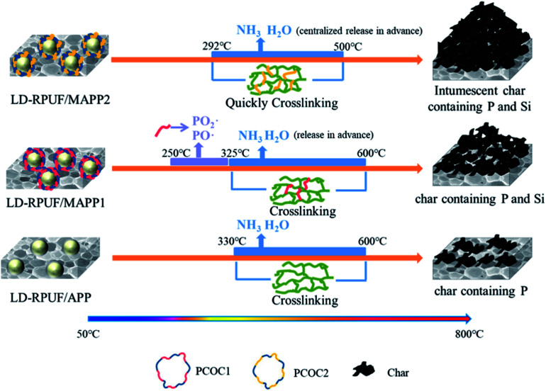
The centralized release of nonflammable gas and quick formation of crosslinked structure increase the flame retardant properties of polyurethane foams.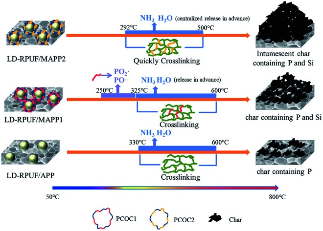
1. Introduction
Rigid polyurethane foam (RPUF), a polymer material, has been widely applied in many fields, such as industrial insulation, the automotive industry, construction, packaging material and household refrigerators, due to its excellent properties, which include low thermal conductivity, light weight, low density, great dimensional stability and good shock absorption.1–4 However, RPUFs are easily ignitable and highly flammable.5 Moreover, RPUFs generate a lot of heat after their ignition and release some toxic gases such as HCN and CO during combustion, which restricts the application of RPUFs and also poses a threat to human safety and health.6,7 Therefore, it is significant to investigate flame-retardant RPUFs.
An intumescent flame-retardant (IFR) can effectively prevent the polymer matrix from further combustion, due to the formation of an intumescent char layer.8 When an IFR is applied in RPUF, the intumescent char layer exerts a barrier effect which can effectively restrain the transfer of heat and the release of some toxic gases generated during the combustion of RPUF.
Ammonium polyphosphate (APP) has been widely used as an IFR in many polymer materials, including RPUF.9,10 It has been reported in the literature that the addition of APP can enhance the flame-retardant properties of high-density RPUF (about 40–50 kg m−3).11,12 However, in our previous work, we found some problems of APP in low-density rigid polyurethane foam (LD-RPUF) (20–30 kg m−3).13 First, the dispersibility and compatibility of APP in LD-RPUF are poor. Second, APP alone has little flame-retardant effect on LD-RPUF. According to the current literature, several methods can be used to overcome these shortcomings. For improving the dispersion, surface modification methods using a silane coupling agent or different compatibilizer and the microencapsulation method have been reported.14–17 APP combined with expandable graphite (EG) or some phosphorus flame retardants such as dimethyl methylphosphonate (DMMP) is used to improve the flame-retardant properties of RPUF.18–20 Different from the current literature, a phosphorus-containing organosilicon compound (PCOC) was designed in our lab and used to modify APP.13 PCOC is not only a surface modification agent for APP, but also a flame retardant, which can play a synergistic flame-retardant role together with APP.
In this work, two phosphorus-containing organosilicon compounds (PCOCs) with similar structure but different phosphorus-containing groups were synthesized. Then, APP was modified with these two kinds of PCOC respectively and modified APP (MAPPs) were obtained. Moreover, the pyrolysis behavior of the two kinds of MAPP was compared. The different work mode and the flame-retardant mechanism of these MAPPs in LD-RPUF were also studied.
2. Experimental
2.1. Materials
Phenyl dichlorophosphate (PDCP) and phenylphosphoryl dichloride (BPOD) were purchased from Shanghai Macklin Biochemical Co., Ltd. Low molecular weight polyether polyol (DP400) was provided by Kukdo Chemical Co., Ltd. γ-Aminopropyltriethoxysilane (KH-550) was provided by Sinopharm Chemical Reagent Co., Ltd. 1,4-Dioxane was supplied by Tianjin Fuchen Chemical Reagents Factory. Tetrahydrofuran (THF) was purchased from Sinopharm Chemical Reagent Co., Ltd. Triethylamine was purchased from Tianjin Kwangfu Fine Chemical Industry Research Institute. APP (n > 1000) was purchased from Hangzhou JLS flame retardants Chemical Co., Ltd. Premixed polyether polyol (ELASTOSPRAY 81305) was purchased from the German BASF Company. The primary properties of ELASTOSPRAY 81305 were as follows: viscosity (25 °C), 640 mPa s; specific gravity (25 °C), 1.18 kg m−3; hydroxyl content, 320 ± 10 mg KOH per g. Polyphenylpolymethylene isocyanate (PAPI, 44V20) was purchased from Covestro Polymers (China) Co., Ltd. The primary performance indices were as follows: NCO weight percent, 30%; monomer methylene diphenyl diisocyanate (MDI) content, 52%. All the chemicals were used as received.
2.2. Synthesis of PCOC
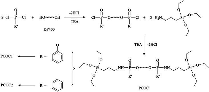
The reaction formula is shown in Fig. 1. PCOC1 was synthesized according to the method reported in our previous literature.21 The synthesis route of PCOC2 was as follows. Phenylphosphoryl dichloride (11.21 g, 0.0575 mol) and 35 ml THF were introduced into a 250 ml three-neck flask with a stirrer, a thermometer, and a dropping funnel. Then 30 ml of a THF solution of DP400 (10 g, 0.025 mol) and triethylamine (5.06 g, 0.05 mol) was added dropwise over a period of 1 h, cooling with an ice bath. After the completion of addition, the reaction temperature was kept at 40 °C for 5 h. After that, a mixture of KH-550 (11.49 g, 0.052 mol), triethylamine (5.06 g, 0.05 mol) and 45 ml THF was added into the reaction system within 1 h at the temperature of 0–5 °C. Then the mixture was kept stirring at 40 °C for 6 h. After filtration and vacuum distillation, a yellow liquid which was PCOC2 was obtained.
Fig. 1. Synthesis of the phosphorus-containing organosilicon compounds.
2.3. Preparation of MAPPs
MAPPs were synthesized according to the methods reported in our previous literature.21 MAPP1 was modified by PCOC1 and MAPP2 was modified by PCOC2. It is important to note that the interactions between APP and PCOC in the MAPPs included both physical absorption and chemical bonding.
2.4. Preparation of flame-retardant LD-RPUFs
The flame-retardant LD-RPUFs were prepared by free-foaming in our laboratory. The compositions of the reaction mixtures are listed in Table 1. The R value (R = –NCO/–OH) of the flame-retardant LD-RPUFs was 1.1. First, polyether polyol and MAPP (or APP) were added into a container with stirring to form a uniform mixture, and then PAPI was immediately poured into the mixture with high-speed (3500–4500 rpm) stirring for 5–10 s. After foaming, the samples required 24 h aging. Then, the foams were cut into standard size pieces for further testing. The density of the foams is shown in Table 1.
The reaction mixtures for the flame-retardant LD-RPUFs.
| Sample | Polyether polyol (g) | PAPI (g) | H2O (g) | APP (g) | MAPP1 (g) | MAPP2 (g) | Density (kg m−3) |
|---|---|---|---|---|---|---|---|
| LD-RPUF/APP | 100 | 100 | 2.5 | 40 | 0 | 0 | 29.5 |
| LD-RPUF/MAPP1 | 100 | 100 | 2.5 | 0 | 40 | 0 | 31.1 |
| LD-RPUF/MAPP2 | 100 | 100 | 2.5 | 0 | 0 | 40 | 29.0 |
2.5. Characterizations
Thermogravimetric analysis (TGA) was performed using a Q50 IR (TA Instruments, USA) thermal gravimetric analyzer. A sample with 4 mg weight was placed in an alumina crucible and heated from 50 °C to 800 °C at a rate of 20°C min−1 under N2 atmosphere.
The limiting oxygen index (LOI) values were obtained using a Dynisco LOI instrument (Fire Testing Technology (FTT), UK) according to ASTM D 2863-97. The sheet dimensions were 100 mm × 10 mm × 10 mm.
The horizontal burning test was performed on an FTT 0082 instrument (Fire Testing Technology Ltd., UK) according to ISO 09772-2001. The dimensions of the samples were 150.0 mm × 50.0 mm × 13.0 mm.
Fire behavior was characterized using an FTT cone calorimeter (Fire Testing Technology Ltd, UK) based on ISO 5660 at an external heat flux of 50 kW m−2. The dimensions of the samples were 100.0 mm × 100.0 mm × 30.0 mm. The cone calorimetry test for each sample was conducted three times, and typical cone calorimetry data were reproducible within ±10%.
The micromorphology images of the residues after cone calorimeter test were obtained by means of a Phenom Pro scanning electron microscope (Phenom World, The Netherlands) under high vacuum conditions with a voltage of 5 kV.
The volatile pyrolysis products of APP and MAPP were characterized using a Mettler-Toledo TGA/DSC-1 thermogravimetric analyzer (METTLER TOLEDO, Switzerland), which was coupled to a Bruker Tensor 27 Fourier-transform infrared spectrometer (TGA-FTIR; Bruker Corporation, Germany). The samples were placed in an alumina crucible and heated from 50 °C to 800 °C at a heating rate of 20°C min−1 under N2 atmosphere.
The residual char of APP and MAPP at desired temperatures was obtained by using a muffle furnace, under air atmosphere. Then the samples were characterized using a Nicolet iN10MX spectrometer (Nicolet Instrument Company, USA) over the frequency range of 500 to 4000 cm−1. Thirty-two scans were used for each measurement.
3. Results and discussion
3.1. Thermal degradation behavior of MAPP
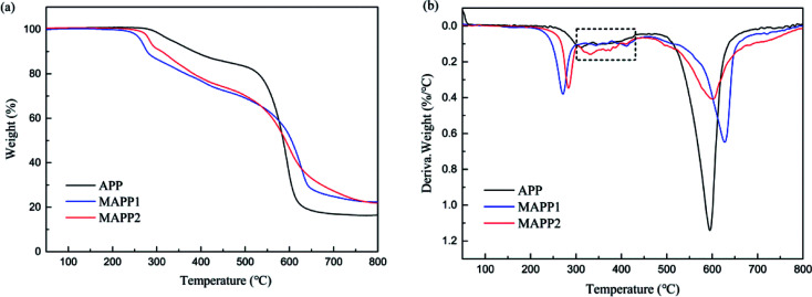
Fig. 2 shows the thermogravimetric analysis (TGA) and derivative thermogravimetric analysis (DTG) curves of APP, MAPP1 and MAPP2. The initial decomposition temperature (Td,5%), the temperature of maximum mass loss rate (Tmax) and the amount of residue are summarized in Table 2. According to the TGA curves, it is noticeable that MAPP showed a three-step thermal degradation process in nitrogen atmosphere, but APP showed a two-step thermal degradation process. The first degradation stage of MAPP occurred before 300 °C, due to the decomposition of PCOC. It can be seen that the Td,5% and Tmax1 of MAPP2 (283.9 °C and 283.4 °C) were both higher than those of MAPP1 (264.4 °C and 271.3 °C), indicating the better thermal stability of MAPP2. The second degradation stage of MAPP occurred from 300 °C to 460 °C. The evolved products at this stage were mainly NH3 and H2O, similar to the first degradation stage of APP.22 Meanwhile, polyphosphoric acid was formed.23 It is noteworthy that the DTG curves of MAPP1 and APP are coincident from 300 °C to 430 °C (shown in the black box), indicating that the decomposition route of MAPP1 was similar to that of APP. In contrast, the derivative weight value of MAPP2 was higher than that of APP in this temperature range, implying that PCOC2 can induce APP to decompose more rapidly than PCOC1. The third degradation stage of MAPP occurred above 460 °C. The temperatures of maximum mass loss rate in this stage (Tmax3) for MAPP1 and MAPP2 were both higher than that of APP. This result suggests that MAPP1 and MAPP2 became more stable at high temperature than APP, owing to the existence of silicon in the PCOCs. Moreover, the residual char values of MAPP1 and MAPP2 at 800 °C were 22.33% and 21.87% respectively, obviously increased compared with APP. This implies that the char-forming ability of APP was enhanced after modification by PCOC.
Fig. 2. TGA curves of MAPPs (a), DTG curves of MAPPs (b).
Data from TGA curves and DTG curves of MAPPs.
| Sample | T d,5% (°C) | T max (°C) | Residue at 800 °C (wt%) | ||
|---|---|---|---|---|---|
| T max1 (°C) | T max2 (°C) | T max3 (°C) | |||
| APP | 333.9 | — | 321.2 | 595.0 | 16.47 |
| MAPP1 | 264.4 | 271.3 | 331.4 | 627.5 | 22.33 |
| MAPP2 | 283.9 | 283.4 | 411.8 | 600.6 | 21.87 |
3.2. Pyrolysis behavior of MAPPs
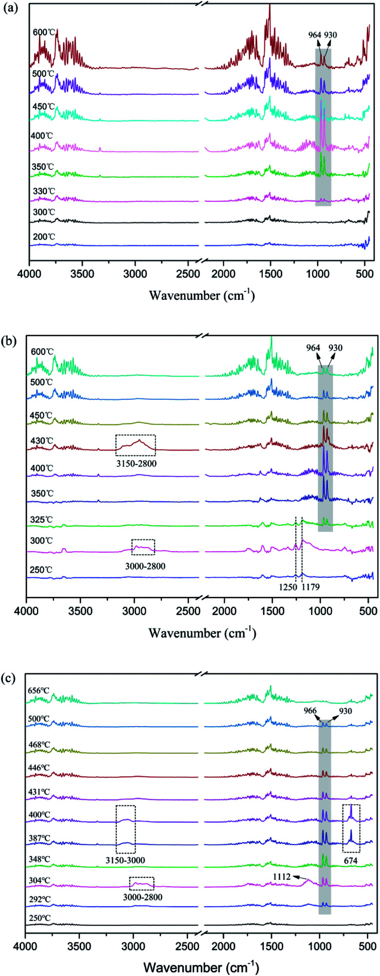
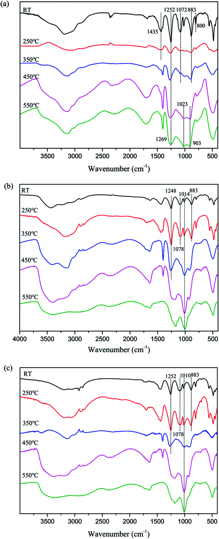
In order to further investigate the flame-retardant mechanism of MAPPs, the Fourier transform infrared (FTIR) spectra of gaseous products and char residues during thermal degradation were obtained from APP, MAPP1 and MAPP2, and they are shown in Fig. 3 and 5, respectively.
Fig. 3. FTIR spectra of gaseous products during thermal degradation of APP (a), MAPP1 (b) and MAPP2 (c) at different temperatures.
Fig. 5. FTIR spectra of char residues during thermal degradation of APP (a), MAPP1 (b) and MAPP2 (c) at different temperatures.
It can be seen from Fig. 3a that the evolved gas products for APP exhibit peaks characteristic of H2O (3734 cm−1, 1518 cm−1) and NH3 (964 cm−1, 930 cm−1). The absorption peak of NH3 appears at about 350 °C and reaches a maximum at 400 °C, then gradually weakens until 600 °C.10,24 For MAPP1, the absorption peaks of NH3 and H2O can be observed from 325–600 °C. This implies that the temperature of NH3 release for MAPP1 was a little lower than that for APP. Moreover, the trend of NH3 release was similar to that for APP. It is noticeable that from 250 °C to 325 °C, two peaks at 1250 and 1179 cm−1 can be ascribed to PO2· and PO·.25 The PO2· and PO· free radicals can quench the flammable free radicals generated by the matrix, which can restrain the free radical chain reaction of combustion, playing a free radical quenching role in the gas phase. The peaks present at 3000–2800 cm−1 and 1112 cm−1 (300 °C) correspond to the C–H and C–O bonds that existed in PCOC1. The peaks at 3150–2800 cm−1 at 430 °C can be ascribed to the C–H bond generated during the decomposition process of aromatic rings.
Analogous considerations are made for MAPP2. The main peaks due to H2O (3734 cm−1, 1518 cm−1) and NH3 (964 cm−1, 930 cm−1) are similar to those for APP and MAPP1. However, the initial release temperature of NH3 is decreased to 292 °C and the temperature range becomes narrow (292–500 °C) for MAPP2. This implies that the initial release temperature of NH3 became lower and the release speed of NH3 became quicker. The earlier release of NH3 is conducive to rapid formation of crosslinked network structure. The peaks which present at 3000–2800 cm−1 and 1112 cm−1 (300 °C) correspond to the C–H and C–O bonds existing in PCOC2, which are also observed in the decomposition products of MAPP1. The peaks at 3150–3000 cm−1 and 674 cm−1 at 387–400 °C prove the existence of aromatic rings in the gas phase.
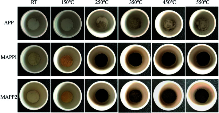
Fig. 4 shows the char residues of APP, MAPP1 and MAPP2 at different temperatures, which were obtained by using a muffle furnace, under air atmosphere. It can be obviously seen that both MAPP1 and MAPP2 had an earlier decomposition than APP, which was reflected by the changed color. When the temperature reached 250 °C, the color of MAPP1 and MAPP2 both changed from yellow to black, which means that char was formed. In contrast, the color of APP did not change from 250 °C to 550 °C, which demonstrated that no char was formed during the decomposition process of APP. This indicates that the char ability of MAPP1 and MAPP2 was greater than that of APP. Moreover, it is noticeable that the residual char colors of MAPP1 and MAPP2 were different above 350 °C. From 350 °C, the char surface color of MAPP2 became lighter because MAPP2 began to intumesce at this temperature and gradually formed an intumescent char. In contrast, the char color of MAPP1 had no obvious change until 550 °C. This reveals that the intumescent char-forming ability of MAPP2 was greater than that of MAPP1.
Fig. 4. Char residues of APP, MAPP1 and MAPP2 at different temperatures.
In addition, the residual char of APP and MAPP at different temperatures was characterized by FTIR. The results are shown in Fig. 5.
As shown in Fig. 5a, at room temperature (RT), the typical absorption peaks of APP included N–H (3184 cm−1), P O (1252 cm−1) and P–O–P (1072 cm−1, 1018 cm−1, 883 cm−1 and 800 cm−1).26 With the temperature increasing, the absorption peaks of –NH4 (1435 cm−1) disappear above 250 °C, which may be associated with the elimination of NH3. The absorption peak of P O (1252 cm−1) move to higher wavenumber above 350 °C, which may also be caused by the elimination of NH3. And at higher temperature (450–550 °C), the presence of absorption peaks at 1252 cm−1, 1023 cm−1 and 911 cm−1 (P O and P–O–P) implies that the final degradation products of APP were phosphorus oxide compounds, such as PO2 and PO3.
In the FTIR spectra of char residues of MAPP1 (Fig. 5b) and MAPP2 (Fig. 5c), the absorption peaks of –NH4 (1435 cm−1) can be observed at 250 °C, which indicates the presence of the element nitrogen in the condensed phase. It also can be obviously seen that the absorption peaks of P–O groups (1078 cm−1 and 883 cm−1) disappear above 350 °C for MAPP1 and MAPP2. Moreover, the peaks at 1100–920 cm−1 become wider and stronger, implying the formation of new chemical structures, such as P–N–C and P–O–C.27,28 The structures of P–N–C and P–O–C can improve the quality and intensity of the char layer.29,30 Meanwhile, absorption bands for Si–O–Si at 1100–1000 cm−1 are observed during the whole process of degradation of MAPP1 and MAPP2, which is the reason for the enhanced thermal stability of the char layer at high temperature.
3.3. Thermal degradation behavior of LD-RPUF/MAPP
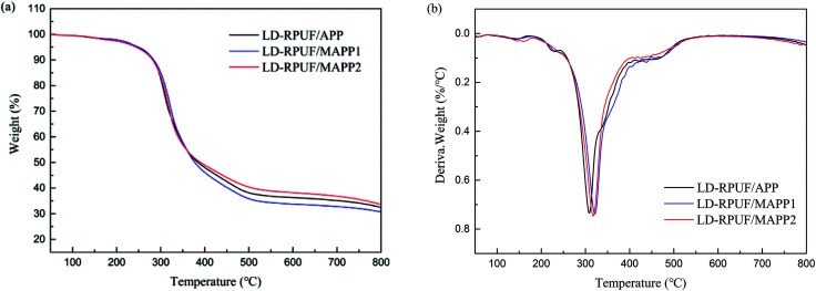
The TGA and DTG curves of LD-RPUF/MAPP are shown in Fig. 6a and b respectively. The initial decomposition temperature of LD-RPUF/MAPP was lower than that of LD-RPUF/APP, owing to the early decomposition of MAPP. However, the Tmax of LD-RPUF/MAPP was much higher than that of LD-RPUF/APP (Table 3). This phenomenon may be due to the residual char yield of LD-RPUF/MAPP2 (33.8%) being higher than that of LD-RPUF/APP (32.4%), whereas the residual char of LD-RPUF/MAPP1 (30.7%) was lower than that of LD-RPUF/APP (Table 3). This indicates that modification of APP by PCOC2 enhanced the charring ability of LD-RPUF during heating in N2 atmosphere.
Fig. 6. TGA curves of LD-RPUF/MAPP (a) and DTG curves of LD-RPUF/MAPP (b).
Data from TGA curves and DTG curves of LD-RPUF/MAPP.
| Sample | T d,5% (°C) | T max (°C) | Residue at 800 °C (wt%) |
|---|---|---|---|
| LD-RPUF/APP | 249.6 | 308.5 | 32.4 |
| LD-RPUF/MAPP1 | 248.3 | 321.1 | 30.7 |
| LD-RPUF/MAPP2 | 244.2 | 317.5 | 33.8 |
3.4. Flame retardancy of LD-RPUF/MAPP
LOI and the horizontal burning test are used to evaluate the flammability of flame-retardant materials. The LOI values and results of the horizontal burning test are presented in Table 4. It can be seen that the LOI value had a small decrease when MAPP was added into LD-RPUF compared with that of LD-RPUF/APP. The LOI value of LD-RPUF/MAPP1 (24.3%) was higher than that of LD-RPUF/MAPP2 (23.6%). This may be due to the release of some PO2· and PO· free radicals in the combustion process of MAPP1, which has been proved in the results of the pyrolysis behavior of MAPP1. The results of the horizontal burning test show that LD-RPUF/APP reached HF-1 rating and both LD-RPUF/MAPP1 and LD-RPUF/MAPP2 kept the same rating. The above results show that there was no obvious difference between MAPP1 and MAPP2 in improving the flame retardancy of LD-RPUF in the horizontal burning test.
Data from LOI test and horizontal burning test.
| Sample | LOI (%) | Horizontal burning rating |
|---|---|---|
| LD-RPUF/APP | 24.4 | HF-1 |
| LD-RPUF/MAPP1 | 24.3 | HF-1 |
| LD-RPUF/MAPP2 | 23.6 | HF-1 |
In order to further investigate the influence of these two kinds of MAPP on the flame retardancy of LD-RPUF, the cone calorimeter test was carried out.
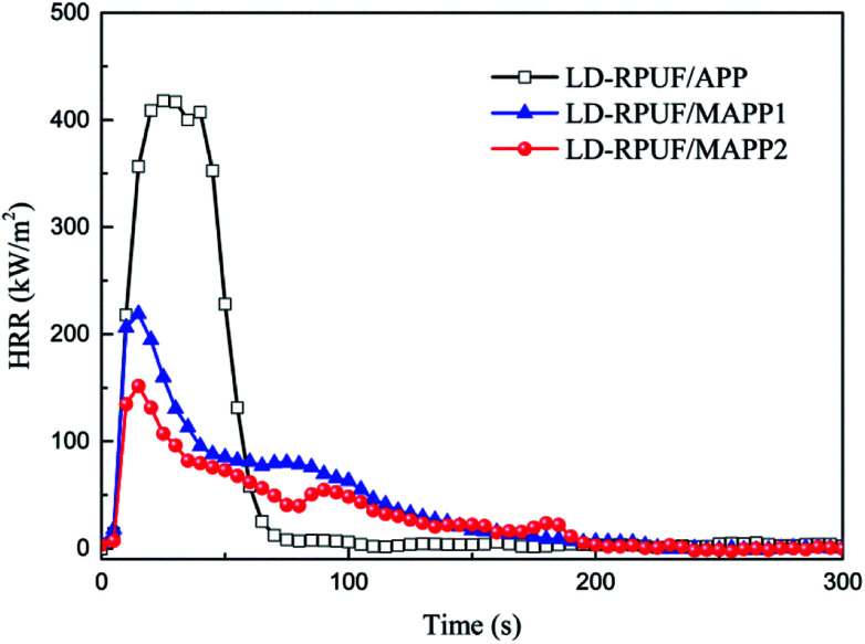
Cone calorimetry is one of the most useful methods to evaluate the combustion behavior of polymers.31 Based on the cone calorimetry test, the heat release rate (HRR) curves and the corresponding experimental data are shown in Fig. 7 and Table 5, respectively.
Fig. 7. Heat release rate (HRR) curves of LD-RPUF/APP and LD-RPUF/MAPP.
Data from cone calorimeter test.
| Sample | pk-HRR | av-EHC | THR | TSR | av-MLR | Char yields |
|---|---|---|---|---|---|---|
| (kW m−2) | (MJ kg−1) | (MJ m−2) | (m2 m−2) | (g s−1) | (%) | |
| LD-RPUF/APP | 418 ± 41 | 21.8 ± 1 | 18.7 ± 4 | 957 ± 47 | 0.015 ± 0.003 | 23.1 ± 1 |
| LD-RPUF/MAPP1 | 220 ± 19 | 19.1 ± 1 | 13.0 ± 2 | 545 ± 31 | 0.012 ± 0.004 | 35.4 ± 0.3 |
| LD-RPUF/MAPP2 | 152 ± 10 | 17.2 ± 0.2 | 9.7 ± 1 | 386 ± 33 | 0.010 ± 0.001 | 44.9 ± 1 |
From Fig. 7, it can be seen that LD-RPUF/APP burns rapidly after ignition and a sharp HRR curve appears with a pk-HRR value of 418 kW m−2, whereas the HRR value has a dramatically decrease when MAPP was added into LD-RPUF. The pk-HRR values of LD-RPUF/MAPP1 and LD-RPUF/MAPP2 were 220 kW m−2 and 152 kW m−2, respectively, which were decreased by 47.4% and 63.6% compared with LD-RPUF/APP. This manifests that both MAPP1 and MAPP2 can reduce the burning intensity of LD-RPUF during combustion. Compared with MAPP1, MAPP2 played a better role in reducing the burning intensity of LD-RPUF.
As presented in Table 5, the average mass loss rates (av-MLR) of LD-RPUF/MAPP1 and LD-RPUF/MAPP2 were lower than that of LD-RPUF/APP, and the av-MLR value of LD-RPUF/MAPP2 was the lowest. Moreover, LD-RPUF/MAPP2 had the highest char yield among the three samples. It was increased by 26.8% compared with LD-RPUF/MAPP1. This implies that MAPP2 promoted the matrix to form more residual char during combustion. This may be due to the good char ability of MAPP2, which has been characterized by the TGA results for MAPP2.
The effective heat of combustion (EHC) is defined as the heat released from the combustion of volatile gas generated from the thermal decomposition of the tested sample, and the EHC value is calculated as the ratio of HRR to the mass loss rate.32 The av-EHC values of LD-RPUF/MAPP1 (19.1 MJ kg−1) and LD-RPUF/MAPP2 (17.2 MJ kg−1) were both lower than that of LD-RPUF/APP (21.8 MJ kg−1). This means that both MAPP1 and MAPP2 had a gaseous-phase flame-retardant effect compared with APP, because, according to the literature, APP does not have a flame-retardant effect in the gas phase.33,34 Compared with LD-RPUF/MAPP1, LD-RPUF/MAPP2 possessed lower av-EHC values, which implies that MAPP2 was better than MAPP1 in increasing the intensity of the gaseous-phase flame-retardant effect. MAPP1 had a gaseous-phase flame-retardant effect in two ways, which are a free radical quenching effect (PO2· and PO· free radicals) and an inflammable gas dilution effect (NH3 and H2O), whereas MAPP2 had a gaseous-phase flame-retardant effect only due to the centralized release of inflammable gas in a short time.
Beyond that, the total heat release (THR) and total smoke release (TSR) of LD-RPUF/MAPP were both dramatically less than those of LD-RPUF/APP. Compared with LD-RPUF/MAPP1, the THR and TSR values of LD-RPUF/MAPP2 were much lower. This result shows that the modification endowed APP with better flame retardancy performance. Moreover, PCOC2 gave APP a better effect in reducing THR and TSR than did PCOC1.
In summary, MAPP enhanced the flame-retardant properties of LD-RPUF by the following processes. First, PCOC induced the decomposition of APP in advance, releasing NH3 and generating polyphosphoric acid in a short time. Then a crosslinked network structure was formed quickly, which was of benefit for the stability of the residual char. Meanwhile, the silicon-containing groups in PCOC formed a ceramic-like protective char layer and improved the stability of the residual char at high temperature, which can be seen from the TGA results of LD-RPUF/MAPP.35 In this process, MAPP1 had a free radical quenching effect and inflammable gas dilution effect in the gas phase and a char-forming effect in the condensed phase. In contrast MAPP2 only had an inflammable gas dilution effect and char-forming effect. However, MAPP2 showed better a flame-retardant effect than MAPP1 in LD-RPUF, which may be attributed to the centralized release of inflammable gas in a short time when MAPP2 was decomposing.
3.5. The analysis of residual char after the cone calorimeter test
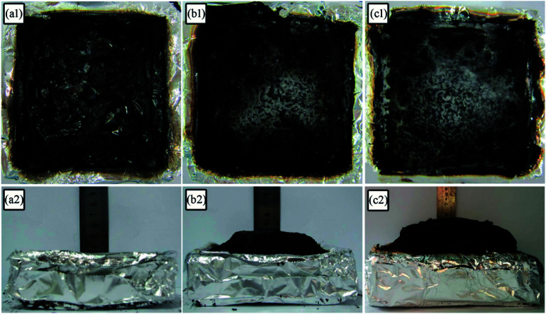
The digital photos of the residual char for LD-RPUF/APP and LD-RPUF/MAPP after the cone calorimetry test are presented in Fig. 8. LD-RPUF/APP left a small quantity of residual char after burning. The residual char of LD-RPUF/APP was discontinuous and existed in islands (Fig. 8a1). This shows that the dispersibility and char-forming ability of APP in LD-RPUF matrix is not good. In contrast, both the residual char of LD-RPUF/MAPP1 and that of LD-RPUF/MAPP2 were more complete, continuous and compact (Fig. 8b1 and c1). It is notable that the residual char of LD-RPUF/MAPP was intumescent, whereas there was no expansion for the residual char of LD-RPUF/APP. In particular, the expansion height of LD-RPUF/MAPP2 was higher than that of LD-RPUF/MAPP1. This may be caused by the centralized release of inflammable gas in a short time when MAPP2 was decomposing.
Fig. 8. Residual char digital photos of LD-RPUF/APP (a), LD-RPUF/MAPP1 (b) and LD-RPUF/MAPP2 (c).
Table 6 shows the element contents of residues after the cone calorimetry test, analyzed by X-ray photoelectron spectroscopy (XPS). For both LD-RPUF/MAPP1 and LD-RPUF/MAPP2, the silicon content in the surface char was higher than that in the interior char, which implies that the silicon in PCOC may migrate to or concentrate on the surface during combustion. This is conducive to forming a ceramic-like protective material on the surface of the residues, which can enhance the compactness of the char layer.36 Moreover, the silicon content in the surface char of LD-RPUF/MAPP2 was twice as much as that of LD-RPUF/MAPP1. It can be inferred that the residual char of LD-RPUF/MAPP2 was more compact than that of LD-RPUF/MAPP1, which was consistent with the macro morphologies of the residual char. In addition, the phosphorus contents in the residual char of LD-RPUF/MAPP2 both in the surface char and also in the interior char were higher than those of LD-RPUF/MAPP1. This is because the phosphorus of MAPP2 was all retained in the condensed phase. Unlike MAPP2, some of the phosphorus in MAPP1 was released into the gas phase in the form of PO2· and PO· free radicals, which decreased the phosphorus content in the condensed phase.
The element contents of the surface char and interior char after cone calorimetry test.
| Sample | C (wt%) | N (wt%) | O (wt%) | P (wt%) | Si (wt%) | |
|---|---|---|---|---|---|---|
| Surface char | LD-RPUF/APP | 25.9 | 2.5 | 51.1 | 20.5 | — |
| LD-RPUF/MAPP1 | 36.7 | 5.3 | 40.1 | 14.5 | 3.4 | |
| LD-RPUF/MAPP2 | 28.1 | 3.3 | 46.7 | 15.1 | 6.8 | |
| Interior char | LD-RPUF/APP | 23.4 | 3.3 | 52.1 | 21.3 | — |
| LD-RPUF/MAPP1 | 55.3 | 5.8 | 26.3 | 10.6 | 1.9 | |
| LD-RPUF/MAPP2 | 57.0 | 5.2 | 25.8 | 10.8 | 1.3 | |
Fig. 9 depicts the scanning electron microscopy (SEM) morphologies of LD-RPUF/APP and LD-RPUF/MAPP after the cone calorimetry test. As shown in Fig. 9a, there were a lot of open cells on the surface of LD-RPUF/APP residual char, which were formed by the release of volatile gas. The open cells weaken the barrier and protective effect of the char layer, increasing the combustion intensity of LD-RPUF/APP. In contrast, it can be observed from Fig. 9b and c that the residual char of LD-RPUF/MAPP1 and LD-RPUF/MAPP2 both exhibited closed cell structure, which is the typical morphology of intumescent flame-retardant systems.37 This structure prevents the release of flammable gas and restrains the oxygen and heat transfer at the same time, which can hinder the further degradation of the material. For LD-RPUF/MAPP2, it is notable that the carbon film covering the closed cell structure was complete and thick. The closed cell structure covered by carbon film is more conducive to exerting a barrier and protective effect during combustion. The carbon film of LD-RPUF/MAPP1 was thinner than that of LD-RPUF/MAPP2. This indicates that MAPP2 can promote the LD-RPUF matrix to form an intumescent char layer with more complete and stable foam during the combustion process compared with MAPP1.
Fig. 9. Scanning electron micrographs of LD-RPUF/APP (a), 2000×, LD-RPUF/MAPP1 (b), 2000× and LD-RPUF/MAPP2 (c), 2000×.
The macro- and micromorphologies of the residual char reveal that modification of APP by PCOC was of benefit for the formation of an intumescent, continuous and compact char layer with closed cells, contributing to the good flame retardancy of LD-RPUF. Furthermore, PCOC2 was more effective than PCOC1.
3.6. The flame-retardant mechanism of MAPP in LD-RPUF
Based on combining the above results, a possible flame-retardant mechanism of MAPP1 and MAPP2 in LD-RPUF is proposed as presented in Fig. 10.
Fig. 10. A possible flame-retardant mechanism of MAPP1 and MAPP2 in LD-RPUF.
First, both PCOC1 and PCOC2 had an induced decomposition effect on APP. They induced the decomposition of APP in advance, rapidly releasing inflammable gases (NH3 and H2O) and generating polyphosphoric acid. The induced decomposition effect of PCOC2 was stronger than that of PCOC1.
Second, some of the phosphorus groups in MAPP1 were released into the gas phase in the form of PO2· and PO· free radicals during this process, which means MAPP1 exerted a quenching effect and gas dilution effect respectively in the gas phase. In contrast, free radicals containing phosphorus were not observed in the degradation products of MAPP2 in the gas phase, which shows that the phosphorus element of PCOC2 exerted a flame-retardant effect mainly in the condensed phase.
In addition, the presence of silicon in PCOC can form a ceramic-like protective char layer, improving the stability of the char layer at high temperature.
4. Conclusion
In this work, two phosphorus-containing organosilicon compounds (PCOC1 and PCOC2) with similar structure but different phosphorus-containing groups were respectively used to modify ammonium polyphosphate (APP). Then, the modified APPs (MAPP1 and MAPP2) were respectively incorporated into low-density rigid polyurethane foam (LD-RPUF). TGA showed that MAPP1 had a lower decomposition temperature, better heat resistance ability at high temperature and greater charring ability than MAPP2. Moreover, when MAPP was added into LD-RPUF, the residual char yield of LD-RPUF/MAPP2 (33.8%) at 800 °C was higher than that of LD-RPUF/MAPP1 (30.7%). Both LD-RPUF/MAPP1 and LD-RPUF/MAPP2 passed HF-1 rating. The cone calorimeter test results showed that the pk-HRR values of LD-RPUF/MAPP1 and LD-RPUF/MAPP2 were 220 kW m−2 and 152 kW m−2, respectively, which were decreased by 47.4% and 63.6% compared with LD-RPUF/APP. The different flame-retardant properties of LD-RPUF/MAPP1 and LF-RPUF/MAPP2 were due to the different flame-retardant mechanisms of MAPP1 and MAPP2. Both MAPP1 and MAPP2 were decomposed early due to the induced decomposition effect of PCOC1 and PCOC2 respectively. Some of the phosphorus-containing groups in MAPP1 were released into the gas phase in the form of PO2· and PO· free radicals, which had a quenching effect in the gas phase. In contrast, the phosphorus in PCOC2 exerted a flame-retardant effect mainly in the condensed phase. The earlier decomposition of PCOC2 induced the decomposition of APP, leading to rapid decomposition of APP with the release of NH3 in a short time and the formation of crosslinked structure quickly. This phenomenon gave MAPP2 a better char ability than MAPP1, which exerted a barrier and protective effect in the condensed phase.
Conflicts of interest
There are no conflicts to declare.
Supplementary Material
Acknowledgments
Financial support was provided by the Young Top-notch Talents Support Project of High-level Teachers in Beijing Municipal Universities in the Period of the 13th Five-year Plan (No. CIT&TCD201704040), the National Nature Science Foundations (No. 51503008) and the Project of the Improved Research Capacity Plan for Postgraduate Students.
References
- Thirumal M. Khastgir D. Singha N. K. Manjunath B. S. Naik Y. P. J. Appl. Polym. Sci. 2008;108:1810–1817. doi: 10.1002/app.27712. [DOI] [Google Scholar]
- Zhu H. B. Peng Z. M. Chen Y. M. Li G. Y. Wang L. Tang Y. Pang R. Khan Z. U. Wan P. Y. RSC Adv. 2014;4:55271–55279. doi: 10.1039/C4RA08429B. [DOI] [Google Scholar]
- Qian L. J. Feng F. F. Tang S. Polymer. 2014;55:95–101. doi: 10.1016/j.polymer.2013.12.015. [DOI] [Google Scholar]
- Xi W. Qian L. J. Huang Z. G. Cao Y. F. Li L. J. Polym. Degrad. Stab. 2016;130:97–102. doi: 10.1016/j.polymdegradstab.2016.06.003. [DOI] [Google Scholar]
- Singh H. Jain A. K. J. Appl. Polym. Sci. 2009;111:1115–1143. doi: 10.1002/app.29114. [DOI] [Google Scholar]
- Xi W. Qian L. J. Chen Y. J. Wang J. Y. Liu X. X. Polym. Degrad. Stab. 2015;122:36–43. doi: 10.1016/j.polymdegradstab.2015.10.013. [DOI] [Google Scholar]
- Yuan Y. Yang H. Y. Yu B. Shi Y. Q. Wang W. Song L. Hu Y. Zhang Y. M. Ind. Eng. Chem. Res. 2016;55:10813–10822. doi: 10.1021/acs.iecr.6b02942. [DOI] [Google Scholar]
- Kuranska M. Cabulis U. Auguscik M. Prociak A. Ryszkowska J. Kirpluks M. Polym. Degrad. Stab. 2016;127:11–19. doi: 10.1016/j.polymdegradstab.2016.02.005. [DOI] [Google Scholar]
- Awad W. H. Wilkie C. A. Polymer. 2010;51:2277–2285. doi: 10.1016/j.polymer.2010.03.033. [DOI] [Google Scholar]
- Luo F. B. Wu K. Lu M. G. Nie S. B. Li X. Y. Guan X. X. J. Therm. Anal. Calorim. 2015;120:1327–1335. doi: 10.1007/s10973-015-4425-3. [DOI] [Google Scholar]
- Zheng Z. H. Yan J. T. Sun H. M. Cheng Z. Q. Li W. J. Wang H. Y. Cui X. J. Polym. Int. 2014;63:84–92. doi: 10.1002/pi.4477. [DOI] [Google Scholar]
- Zhang M. Zhang J. W. Chen S. G. Zhou Y. H. Polym. Degrad. Stab. 2014;110:27–34. doi: 10.1016/j.polymdegradstab.2014.08.009. [DOI] [Google Scholar]
- Chen Y. J. Li L. S. Wang W. Qian L. J. J. Appl. Polym. Sci. 2017;134:45369. doi: 10.1002/app.45369. [DOI] [Google Scholar]
- Wang B. B. Qian X. D. Shi Y. Q. Yu B. Hong N. N. Song L. Hu Y. Composites, Part B. 2015;69:22–30. doi: 10.1016/j.compositesb.2014.09.015. [DOI] [Google Scholar]
- Wang W. Zhang S. F. Wang F. Yan Y. T. Li J. Z. Zhang W. Polym. Compos. 2016;37:666–673. doi: 10.1002/pc.23223. [DOI] [Google Scholar]
- Yan H. W. Wei J. L. Yin B. Yang M. B. Polym. Bull. 2015;72:2725–2737. doi: 10.1007/s00289-015-1432-2. [DOI] [Google Scholar]
- Li R. M. Deng C. Deng C. L. Dong L. P. Di H. W. Wang Y. Z. RSC Adv. 2015;5:16328. doi: 10.1039/C4RA15971C. [DOI] [Google Scholar]
- Hu X. M. Wang D. M. J. Appl. Polym. Sci. 2013;129:238–246. doi: 10.1002/app.38722. [DOI] [Google Scholar]
- Meng X. Y. Ye L. Zhang X. G. Tang P. M. Tang J. H. Li Z. M. J. Appl. Polym. Sci. 2009;114:853–863. doi: 10.1002/app.30485. [DOI] [Google Scholar]
- Xu W. Wang G. J. Zheng X. R. Polym. Degrad. Stab. 2015;111:142–150. doi: 10.1016/j.polymdegradstab.2014.11.008. [DOI] [Google Scholar]
- Chen Y. J. Li L. S. Xu L. F. Qian L. J. J. Appl. Polym. Sci. 2018;135:46334. doi: 10.1002/app.46334. [DOI] [Google Scholar]
- Lin H. J. Yan H. Liu B. Wei L. Q. Xu B. S. Polym. Degrad. Stab. 2011;96:1382–1388. doi: 10.1016/j.polymdegradstab.2011.03.016. [DOI] [Google Scholar]
- Qin Z. L. Li D. H. Yang R. J. Polym. Degrad. Stab. 2016;126:117–124. doi: 10.1016/j.polymdegradstab.2016.01.022. [DOI] [Google Scholar]
- Lai X. J. Qiu J. D. Li H. Q. Zhou R. M. Xie H. L. Zeng X. R. J. Anal. Appl. Pyrolysis. 2016;120:361–370. doi: 10.1016/j.jaap.2016.06.004. [DOI] [Google Scholar]
- Wang J. Y. Qian L. J. Xu B. Xi W. Liu X. X. Polym. Degrad. Stab. 2015;122:8–17. doi: 10.1016/j.polymdegradstab.2015.10.011. [DOI] [Google Scholar]
- Xu Z. Z. Huang J. Q. Chen M. J. Tan Y. Wang Y. Z. Polym. Degrad. Stab. 2013;98:2011–2020. doi: 10.1016/j.polymdegradstab.2013.07.010. [DOI] [Google Scholar]
- Jia P. Y. Zhang M. Liu C. G. Hu L. H. Feng G. D. Bo C. Y. Zhou Y. H. RSC Adv. 2015;5:41169–41178. doi: 10.1039/C5RA05784A. [DOI] [Google Scholar]
- Jia P. Y. Zhang M. Hu L. H. Zhou J. Feng G. D. Zhou Y. H. Polym. Degrad. Stab. 2015;121:292–302. doi: 10.1016/j.polymdegradstab.2015.09.020. [DOI] [Google Scholar]
- Jia P. Y. Hu L. H. Zhang M. Zhou Y. H. J. Therm. Anal. Calorim. 2016;124:1331–1339. doi: 10.1007/s10973-015-5199-3. [DOI] [Google Scholar]
- Jia P. Y. Zhang M. Hu L. H. Bo C. Y. Zhou Y. H. Thermochim. Acta. 2015;613:113–120. doi: 10.1016/j.tca.2015.05.011. [DOI] [Google Scholar]
- Li C. Wan J. T. Kalali E. N. Fan H. Wang D. Y. J. Mater. Chem. A. 2015;3:3471–3479. doi: 10.1039/C4TA05740F. [DOI] [Google Scholar]
- Qiu Y. Qian L. J. Xi W. Liu X. X. J. Appl. Polym. Sci. 2016;133:43241. [Google Scholar]
- Liu Y. L. He J. Y. Yang R. J. Ind. Eng. Chem. Res. 2015;54:5876–5884. doi: 10.1021/acs.iecr.5b01019. [DOI] [Google Scholar]
- Xu W. Wang G. J. Zheng X. R. Polym. Degrad. Stab. 2015;111:142–150. doi: 10.1016/j.polymdegradstab.2014.11.008. [DOI] [Google Scholar]
- Wang X. F. Zhan J. Xing W. Y. Wang X. Song L. Qian X. D. Yu B. Yuan H. Ind. Eng. Chem. Res. 2013;52:5548–5555. doi: 10.1021/ie3033813. [DOI] [Google Scholar]
- Chen X. L. Hu Y. Song L. Polym. Eng. Sci. 2008;48:116–123. doi: 10.1002/pen.20918. [DOI] [Google Scholar]
- Ma H. Y. Fang Z. P. Thermochim. Acta. 2012;543:130–136. doi: 10.1016/j.tca.2012.05.021. [DOI] [Google Scholar]


