Abstract
Mining-induced fractures often constitute water inrush channels, which lead to mine water inrush accidents. In this paper, a coupled model of stress–seepage–damage based on micromechanics is established, which simulates the initiation and propagation of cracks in rock materials and their interaction with fluid flow. The method combines the continuous damage model with the effective stress principle, in which the elastic modulus and permeability are related to the damage variables. The model is implemented via the COMSOL code based on the finite element method, and the reliability of the model is verified by the axial compression–seepage test of standard rock samples. According to the actual geological conditions of F13 fault in Wugou Coal Mine, Anhui Province, the damage of the floor rock mass and the risk of fault water inrush in the 1033 mining face with 50, 40, 30, and 20 m waterproof coal pillars are predicted. When the coal pillar width is 30 or 20 m, the fault, the surrounding rock of the fault, and the failure zone of the floor constitute the water inrush channel. This model provides an intuitive understanding of the rock damage and water inrush evolution, which is difficult to observe, and will contribute to prevent water inrush disasters in practical engineering.
1. Introduction
Fault is one of the most common geological structures during underground mining. Faults destroy the continuity and integrity of rock strata and often become the inducing factor of mine disasters. During underground mining activities, the dynamic change of the stress field of the surrounding rock leads to the initiation and expansion of fractures. The existence of faults not only affects the redistribution of the stress field but also may become a potential water diversion channel when connected with mining-induced fractures.1−3 According to incomplete statistics, more than 80% of the mine water inrush accidents in coal mines are related to faults,4 causing heavy casualties and property losses. Therefore, the faults have become the key factor affecting the prevention and control of water inrush in mines.
In recent years, many scholars have done a lot of research on the mechanism of water inrush from faults. Cheng et al. used FLAC3D numerical simulation software based on the coupling of the stress field and seepage field to systematically analyze the plastic failure of rock mass caused by fault dip angle, fault fracture zone width, and aquifer pressure.5−7 However, the formation of the water inrush channel was not due to the plastic deformation of rock mass but rather due to the expansion of mining-induced fractures.8 Through physical simulation, Zhang9 studied the formation process of cracks and the evolution of high-pressure water inrush channel under the floor and considered that the connection between the structural rock zone and cracks in the coal floor was the direct cause of water inrush from the coal floor. Zhou10 used the extended finite element method and fracture mechanics to carry out numerical simulation, quantitatively analyzed the stress field at the tip of the fault, and evaluated the possibility of water inrush from fault activation. Qian11 investigated the evolution process of a fault water inrush accident in Tianzhuang Coal Mine, Jining City, Shandong Province, and found that groundwater in the Ordovician limestone aquifer 28.5 m below the floor flows into the roadway through the fault zone. Ma12,13 conducted a lot of mechanical tests on gangue, granite, and paste in underground mining and obtained the characteristics of deformation, failure, and permeability. These efforts constantly improve and supplement the mechanism of fault water inrush, but there are also limitations in predicting the fracture of the floor rock mass and water inrush channel, and the evolution of water inrush from faults in the coal seam floor has not been fully recognized.
In fact, the water inrush from faults is caused by the reactivation of the original water-conducting or non-water-conducting faults under the influence of mining stress, which leads to the re-expansion of the fractures in the fault zone and its adjacent rock mass, resulting in the change of its permeability. When connected to an aquifer, it will cause water inrush.14 Therefore, the process of fault water inrush essentially involves the multiscale coupling of rock stress, damage, and seepage, and the existing rock mechanics theory or numerical calculation method cannot perform an in-depth analysis of it. The establishment of theoretical models and numerical calculation methods to accurately reflect the fractures, seepage evolution, and seepage characteristics of the floor rock mass structure is a key scientific issue involved in the study of the water inrush mechanism.
Damage variable is the cumulative response of rock samples in the process of progressive failure, and it is an important factor in characterizing the phenomenon of rock failure.15 Based on the internal damage variables of rock, many scholars have explored the process of rock failure and crack propagation under different loading modes. The evolution process of damage variablea is closely related to the temporal and spatial evolution of the stress field.16 The damage evolution of rock is a nonlinear dynamic process with localization and inhomogeneity.17 Many important hydromechanical phenomena such as stress perturbation, pore pressure fluctuation, damage evolution, and fracture deformation are realistically captured in numerical simulation.18 For this reason, the internal failure process of rock is revealed by calculating damage variables.
In this paper, a coupled micromechanical model of rock stress–seepage–damage is established to describe the process of rock fracture and seepage, which is verified by the compression–seepage test of standard rock samples. Based on this model, progressive failure, stress concentration, and seepage evolution of rock during loading can be captured. On this basis, combined with the specific geological conditions of Wugou Coal Mine in Anhui Province, the danger of water inrush under different width waterproof coal pillars of the F13 fault is predicted, and the evolution process of floor rock mass and water inrush is analyzed, which provides guidance for practical engineering.
2. Stress–Seepage–Damage Coupling Model
2.1. Heterogeneity Hypothesis
Rock is a mixed material composed of mineral particles and cement. Due to the influence of the complex external environment in the formation process, the matrix particles and microdefects show significant heterogeneity. To consider the heterogeneity of rock, the appropriate-scale RVE (representative volume element) is usually selected according to the distribution characteristics of rock mineral particles and microdefects, and the statistical method is used to endow the rock RVE with physical and mechanical parameters that obey a certain probability distribution so as to transform the mesofabric properties of rock heterogeneity into macroscopic material properties.19 For a certain parameter u of rock, it is assumed that it obeys Weibull distribution, and its probability density function expression is given by20
| 1 |
where u is a certain parameter of rock; u0 is a scale parameter, which is related to the mean value of material parameters; and m is a shape parameter, which characterizes the uniformity of materials.
Then, the cumulative probability function is written as
| 2 |
The Monte Carlo method is used to generate a set of random number sequence ζ that obeys the uniform distribution of interval (0, 1). By making the probability distribution function F(u) = ζ, the parameters of any rock microelement can be written as
| 3 |
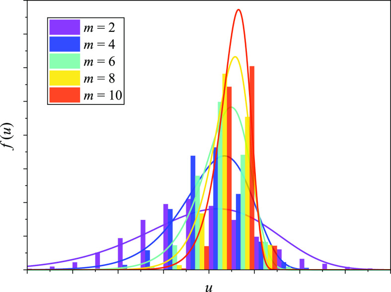
Figure 1 shows the Weibull distribution of material properties with different homogeneity indices m. Obviously, when the homogeneity index m has a relatively high value, the mechanical properties and physical parameters of the mesoscale elements in the rock accumulate in a very small range, which reflects the relative homogeneity of the rock.
Figure 1.
Weibull distribution for material properties with different indices m.
2.2. Statistical Damage Constitutive Model
Based on the principle of the strain equivalence and the concept of effective stress,21,22 the linear elastic constitutive model of a damaged material adopts the following formula
| 4 |
The elastic modulus of the element degrades monotonously with the development of the damage, and the elastic modulus of the damaged material is defined as follows
| 5 |
where σ is the stress; E and E0 are Young’s modulii of damaged and undamaged materials, respectively; ϵ is the elastic strain; and D is the damage variable. In order to avoid the problem caused by the elastic modulus of zero, when D = 1.0, the elastic modulus of the damage element is designated as a very small value, such as 1.0 × 10⁻⁵ MPa.
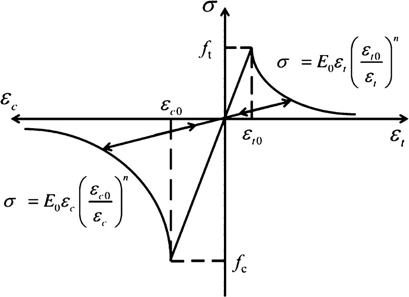
As shown in Figure 2, the damage constitutive relation of the element under uniaxial compressive stress and tensile stress is used to simulate the failure. At first, the element was considered to be elastic, and its elastic properties were defined by Young’s modulus and Poisson’s ratio. Accordingly, the stress–strain relationship of the element is considered to be linear elastic until the given damage threshold is reached and then modified by softening.
Figure 2.
Elastic damage constitutive law of an element subjected to uniaxial stress.
The maximum tensile stress criterion and Mohr–Coulomb criterion are used to test the stress state of the element, which, respectively, reflect the main damage and fracture modes of rock, and the tensile stress criterion is given priority. When the stress state meets a certain criterion, the element begins to accumulate tensile or shear damage.
The discriminant of tensile failure is the maximum tensile stress criterion, which is calculated as follows
| 6 |
where σ1 is the maximum principal stress and ft is the tensile strength. At this time, the damage variable of the element is described as follows
 |
7 |
where ϵt0 is the elastic limit tensile strain in the case of tensile failure of the element and ϵt is the maximum principal strain, and under the condition of multi-axial stress, it is equal to the equivalent principal strain in the tensile state, which can be expressed as follows
| 8 |
where ϵ1, ϵ2, and ϵ3 are the three principal strains and ⟨⟩ is a symbolic function defined as follows
| 9 |
The criterion of shear failure is the Mohr–Coulomb criterion, which is expressed as follows
| 10 |
where φ is the angle of internal friction and fc is the compressive strength. Also, the damage variable of the element is described as follows
 |
11 |
where ϵc0 is the elastic limit compressive strain of the element when shear failure occurs and ϵc is the minimum principal strain, which can be expressed as
| 12 |
2.3. Stress–Seepage–Damage Coupling Model
The fluid–solid coupling behavior of geotechnical materials has always been a hot topic in the field of geotechnical engineering. Based on the widely accepted Biot’s consolidation theory, it has been developed to include the permeability change caused by rock fracture.23,24
Equilibrium equation is given as
| 13 |
where σij represents the component of the Cauchy stress tensor and fj is the body force in the jth direction.
Geometrical equation is given as
| 14 |
where ϵij is the component of the Cauchy’s strain tensor and ui is the displacement in the jth direction.
Constitutive equation is given as
| 15 |
where  is the component of the effective stress
tensor; p is the pore pressure; δij is the Kronecker function; ϵv is
the volumetric strain, which is defined as ϵv = ϵii; G is the shear modulus
of the material, which is defined as G = E/[2(1 + v)]; α is Biot’s coefficient; and λ is
Lame’s coefficient, which is defined as λ = Ev/[(1 + v) (1 – 2v)].
The Navier equilibrium equation under stress–seepage coupling can be obtained by the above equations, as shown below
| 16 |
Based on the mass conservation equation of fluid and Darcy’s law, the isothermal seepage control equation considering solid deformation can be obtained as25
| 17 |
where 1/S is the water storage coefficient; k is the permeability; and μ is the fluid viscosity.
The stress state of the rock will affect the porosity, and this relationship can be expressed as26
| 18 |
where ϕ is the porosity; ϕ0 is the initial porosity; ϕr is the limited
value of porosity under high compression stress, which is about 0;
αϕ is the stress sensitivity coefficient of
porosity, such as 5.0 × 10⁻⁸ Pa–1; and  is the average
effective stress, which
is expressed as follows
| 19 |
When the damage and gradual failure of the unit converge into a fracture, the permeability of the fracture has a step compared with the matrix permeability, and the change of permeability can be expressed as27
| 20 |
where k0 is the initial permeability and αk is the influence coefficient of damage on permeability.
2.4. Model Solving Process
The solution process of rock stress–seepage–damage coupling model is shown in Figure 3. This model describes the coupling relationship among mechanical deformation, seepage, and damage and can be used to analyze the damage and failure process of rock materials under the condition of fluid–solid coupling.
Figure 3.
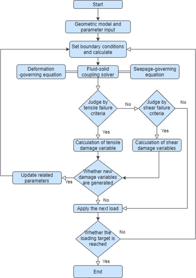
Flow chart for solving the stress–seepage–damage coupling model.
3. Model Validation
In order to verify the reliability of the model in this paper, compression–seepage tests of standard rock samples including rock deformation, seepage, and fracture processes are carried out, and the results of laboratory tests and numerical simulation are compared.
The equipment used in the laboratory is the rock top multifield coupling testing system, as shown in Figure 4. The equipment consists of an axial pressure system, a confining pressure system, a seepage system, a special LVDT displacement sensor, and a radial deformation sensor and can realize conventional triaxial compression–seepage test. The maximum axial stress is 500 MPa, and the maximum confining pressure is 60 MPa. The maximum osmotic pressures at the upper and lower ports are 60 and 50 MPa, respectively. Two LVDT displacement sensors are used to measure the axial deformation, with a measuring range of 12 mm and the accuracy of 0.001 mm.
Figure 4.
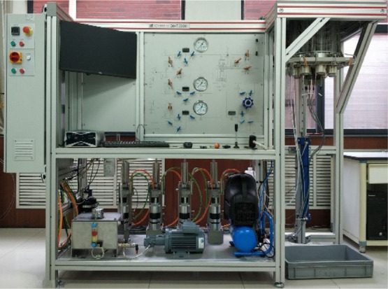
Rock top multifield coupling testing system.
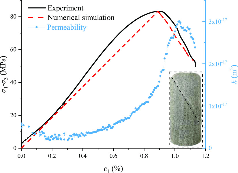
The sandstone sample with dimensions of ϕ 50 mm × 100 mm were used in the test. The sample was saturated before loading into the triaxial pressure chamber. The top water pressure is 1 MPa, and the bottom water pressure is 0. The confining pressure is 2 MPa, and the axial displacement is applied at a rate of 0.02 mm/min until the sample is significantly damaged. The stress–strain curve and permeability changes obtained during loading are shown in Figure 5, which represent the whole process of deformation, gradual failure, and ultimate loss of the bearing capacity of rock. The permeability changes correspondingly with the compression and closure of the original pores and microcracks and the initiation and propagation of cracks and reaches the maximum value when it develops into a macroscopic shear plane.
Figure 5.
Stress–strain and permeability curves of the rock sample.
During the test process, a stable water pressure difference is formed between the inlet and outlet. Darcy’s law is used for measuring the permeability of the sandstone sample. The expression is as follows
| 21 |
where k is the permeability in time Δt (m2); μ is the dynamic viscosity of water (Pa•s); Q is the volume of water flowing through the sandstone sample in time Δt (m3); L is the height of the sample (m); A is the cross-sectional area of the sample (m2); ΔP is the water pressure difference between two extremities of the sample (Pa); and Δt is the interval between recording points (s).
The COMSOL code is used for the numerical simulation, and its open interface can realize the calculation of the multifield coupling model in this paper. The size of the plane’s geometric model is 50 mm × 100 mm, and the boundary conditions are consistent with those of the conventional triaxial compression–seepage test.
As shown in Figure 6, a constant confining pressure is applied on the left and right boundaries of the model, the bottom boundary of the model is constrained by vertical displacement, and the top boundary is loaded vi axial displacement to control the load. Each step increases the displacement by 0.01 mm until the sample appears macroscopically damaged. The steady-state seepage model is adopted for simulation, where the left and right boundaries of the sample are impervious, the top boundary is applied with a constant water pressure of 2 MPa, and the water pressure at the bottom boundary is 0 MPa. To characterize the heterogeneity of rock materials, it is assumed that the initial mechanical parameters meet the Weibull distribution, and the mechanical parameters and seepage parameters used are shown in Table 1.
Figure 6.
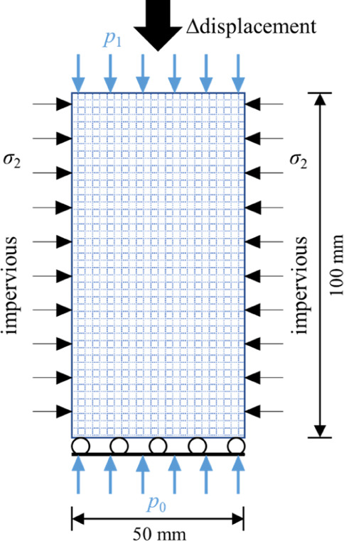
Numerical calculation model of the axial compression–seepage test.
Table 1. Material Parameters.
| elastic modulus E | Poisson’s ratio v | internal friction angle φ | compressive strength fc | tensile strength ft | permeability k | porosity ϕ | fluid viscosity μ | heterogeneity coefficient m |
|---|---|---|---|---|---|---|---|---|
| 12 GPa | 0.32 | 30° | 80 MPa | 5 MPa | 5 × 10–18 m2 | 0.08 | 0.001 Pa s | 3 |
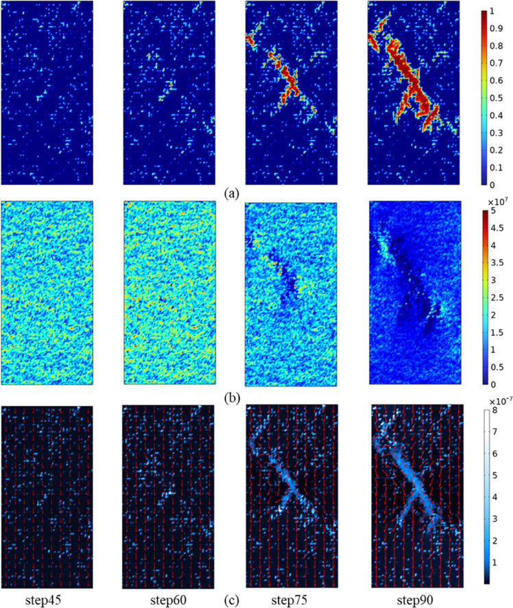
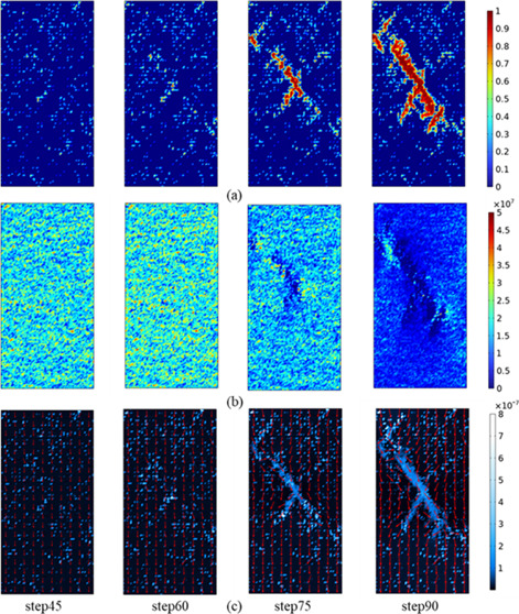
The evolution of damage, stress, and seepage velocity in the process of rock compression–seepage is shown in Figure 7. During the initial external stress loading process, there are randomly distributed damage points in the sample. Then, with the stress loading, the randomly distributed damaged areas continue to expand and merge, and the cracks meet and penetrate. At the same time, the local stress concentration gradually increases. During the loading process, the rock mainly exhibits shear failure and finally forms a macro fault zone and becomes the main seepage channel. This is very consistent with the phenomenon observed in a large number of rock mechanics experiments.28−30 Therefore, the coupling model of rock stress–seepage–damage can better simulate the progressive failure process of rock under load.
Figure 7.
Damage, stress, and seepage velocity during numerical simulation: (a) damage, (b) stress, and (c) seepage velocity.
4. Application in Water Inrush from Faults in Coal Mines
In the process of coal seam mining, when the abutment pressure of the coal seam floor reaches or exceeds the critical strength of the floor rock, the rock mass within a certain range of the floor of the working face may be destroyed, resulting in brittle fracture, which is called zero-order fracture.4 The most representative theory of “lower three zones” vividly describes the floor failure zone, effective water-resisting zone, and confined water guiding zone in the mining process.31 The ratio of aquifer water pressure to aquifer thickness is also often used as the water inrush coefficient to analyze the risk of water inrush from the floor.32 However, in the mining process, the redistribution of the stress field leads to the activation of the fault, which further enhances the permeability of the fault zone. When connecting with the floor failure zone, a potential water inrush channel is formed, as shown in Figure 8.
Figure 8.
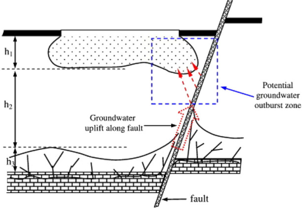
Water inrush channel from the fault. Reused with permission of ref (2), Copyright@Elsevier, 2022.
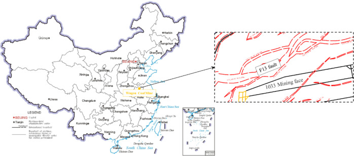
Wugou Coal Mine is located in Huaibei City, Anhui Province, China, as shown in Figure 9. The F13 fault is located in the north-central part of the Wugou mine and in the south of the 1033 mining face. It is a large normal fault with an inclination of 60–70°, a fall of 10–200 m, and a fault width of 260 m. The fillings are mostly a sand–mudstone mixture containing expansive minerals. It is determined by on-site drilling that the hydraulic conductivity of the fault is poor and it is a non-water-conducting fault. #10 coal are mined in the 1033 mining face, with a buried depth of 450–550 m. The occurrence of the coal seam is relatively simple, with a coal thickness of 3.55–5.51 m and an average of 4 m. Medium sand and silty sand are mainly found in the 30 m range of the roof; silty sand and mudstone are mainly found in the range from the floor to ash; and siltstone is found in the straight bottom of the coal seam. The distance between #10 coal and Taiyuan Formation is 36.66–47.84 m, with an average distance of 41.96 m. The main threat of water inrush during mining comes from the limestone water of Taiyuan Formation below the coal seam (the measured water pressure is 3.24 MPa). Although there is a waterproof layer with a certain thickness in the floor rock mass, the mining process of the 1033 mining face is still threatened by water inrush due to the influence of the F13 fault. Based on the model in this paper, the water inrush of the mining fault under the condition of waterproof coal pillars with different widths is predicted, and a reasonable coal pillar size is proposed.
Figure 9.
Location of Wugou Coal Mine.
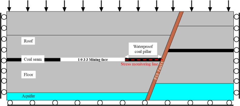
The plane strain model shown in Figure 10 is established, whose geometric dimension are 300 m × 116 m, a fault dip angle of 70°, a fault width of 4 m, and the confined aquifer water pressure is 3 MPa. The vertical compressive stress of 8.0 MPa is applied to the top boundary to express the weight of the overlying rock. Normal displacement constraints are set on the left, right, and bottom boundaries. In order to simulate the actual situation of the roof caving in the goaf, before the next advance, the last advance section should be filled. A vertical stress monitoring line is set in the fault waterproof coal pillar. In this paper, the pressure is positive and the tension is negative. Table 2 lists the material parameters used. The damage and water inrush evolution of coal mining under the conditions of 20, 30, 40, and 50 m waterproof coal pillars are simulated, respectively.
Figure 10.
Geometric models and boundary conditions.
Table 2. Material Parameters.
| rock stratum | elastic modulus E (GPa) | Poisson’s ratio v | internal friction angle φ (deg) | compressive strength fc (MPa) | tensile strength ft (MPa) | density ρ (kg/m3) | porosity ϕ | permeability k (m2) |
|---|---|---|---|---|---|---|---|---|
| roof | 24 | 0.25 | 33 | 32 | 2 | 2720 | 0.28 | 2.2 × 10⁻¹³ |
| fault | 2 | 0.35 | 26 | 4 | 0.5 | 2000 | 0.44 | 4.0 × 10⁻¹³ |
| coal seam | 2.6 | 0.33 | 28 | 18 | 1.2 | 1400 | 0.35 | 4.1 × 10⁻¹⁴ |
| floor | 15 | 0.23 | 28 | 22 | 1.5 | 2650 | 0.25 | 3.6 × 10⁻¹³ |
| aquifer | 8.7 | 0.28 | 30 | 45 | 3.6 | 2760 | 0.42 | 1.3 × 10⁻¹¹ |
| filling | 0.5 | 0.40 | 26 | 12 | 1 | 2000 | 0.40 | 4.1 × 10⁻¹⁴ |
5. Results and Discussion
5.1. Stress Evolution
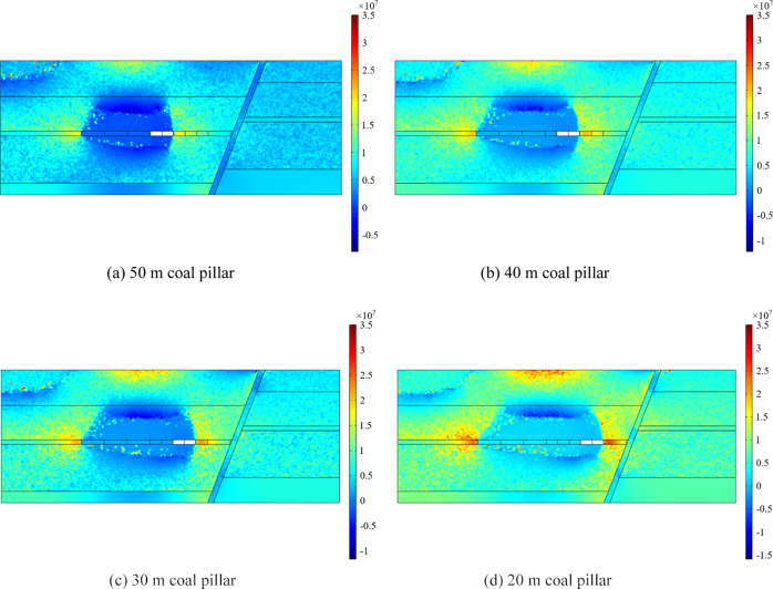
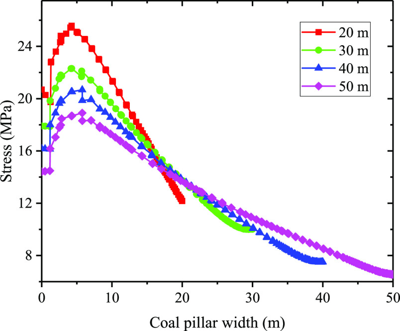
Figure 11 shows the stress distribution when the waterproof coal pillars of 50, 40, 30, and 20 m are left in the hanging wall mining of the F13 fault. It can be seen from the figure that the stress is redistributed after the coal seam mining, showing tensile stress within a certain range of the roof and floor of the mining face and compressive stress distributed around the coal pillar. With the increase of mining area, the stress concentration around the coal pillar becomes more obvious. The smaller reserved width of the waterproof coal pillar means that the coal pillar bears more stress, as shown in Figure 12. As the width of the coal pillar is decreased, the internal stress of the fault increases to varying degrees. At the same time, due to the barrier effect of the fault on the deformation and stress transfer of the rock mass,33,34 the stress concentration in the hanging wall of the fault is more obvious when mining near the fault.
Figure 11.
Stress distribution of 50, 40, 30, and 20 m waterproof coal pillars.
Figure 12.
Stress distribution along the stress monitoring line in coal pillars with different widths.
5.2. Damage Evolution
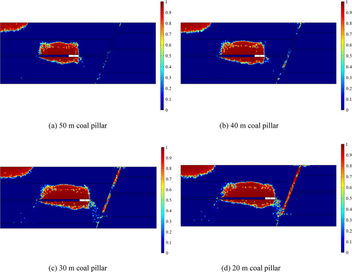
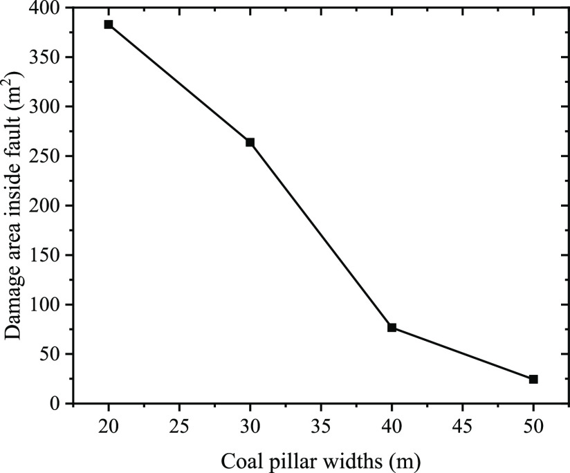
Figure 13 shows the damage distribution in the case of 50, 40, 30, and 20 m waterproof coal pillars of the F13 fault. It can be seen from the figure that after coal seam mining, the stress is redistributed, and a certain range of damage areas appear in the roof and floor. Combined with the stress distribution in Figure 11, they can be understood as the roof caving zone, fracture zone, and floor failure zone after coal mining. In addition, due to the change of internal stress in the fault during mining, there are different degrees of damage in the fault. The damage area inside the fault under the condition of retaining coal pillars with different widths is counted, as shown in Figure 14. When the coal pillar width is 50 and 40 m, respectively, the internal failure area of the fault under the influence of mining is 24.4 and 76.6 m2, respectively, accounting for only a small portion. When the waterproof coal pillar gradually shrinks to 30 and 20 m, respectively, the damaged area in the fault rapidly increases to 263.9 and 382.94 m2, respectively, which indicates that the filling in the fault has lost its original integrity and its permeability suddenly increases. At the same time, the surrounding rock of the fault is also damaged in a large scale. Combined with the stress distribution, it is a shear failure zone, which is connected with the floor failure zone, forming a water inrush channel of “aquifer–fault–floor”.
Figure 13.
Damage distribution under the condition of 50, 40, 30, and 20 m coal pillars.
Figure 14.
Damage distribution under the condition of 50, 40, 30, and 20 m coal pillars.
5.3. Prediction of Water Inrush
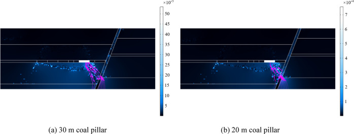
According to the seepage velocity cloud map and flow line in Figure 15, when the width of the fault waterproof coal pillar is 30 or 20 m, the fault, the surrounding rock of the fault and the floor failure zone constitute the water inrush channel under the influence of mining. At this time, the flow of water inrush from the working face reaches 720 and 1008 m3/h, respectively, which both exceed the normal flow rate of 253.68 m3/h and maximum flow rate of 619.53 m3/h of Wugou Coal Mine. However, the obvious water inrush channel will not be formed when the width of the fault waterproof coal pillar is 40 or 50 m. Therefore, according to the prediction results of this model, it is safe and reasonable to set up a 40 m waterproof coal pillar in the F13 fault of Wugou Coal Mine. According to this conclusion, in actual operation, the 1033 working face has been mined safely without water inrush.
Figure 15.
Seepage velocity cloud map and flow line under the condition of 30 and 20 m coal pillars.
In a word, the above differences are caused by different pillar widths, which cause different local stress concentrations during mining. When the width of the pillar is too small, once the floor rock exceeds its strength limit, it will be gradually destroyed and connected together, thus forming a permeable channel in the rock. This channel provides space for the aquifer to discharge to the working face. When it exceeds the drainage capacity of the mine, it will become a water inrush channel. Through the work of this paper, the progressive destruction process of rock and the evolution of water inrush field during coal seam mining can be effectively captured, thus providing early warning for the water inrush hazard and ideas for water inrush prevention and control.
6. Conclusions
Understanding the evolution mechanism of the water inrush disaster is of great significance to the safe mining of coal resources on confined aquifers. In this paper, a coupled numerical model of rock stress–seepage–damage based on micromechanics is established, and the initiation and propagation of cracks in rock materials and their interaction with fluid flow are simulated. This method can be used to explore complex mechanical behaviors that are difficult to be observed directly in underground coal mining, such as rock mass damage and water inrush.
The model is realized by the secondary development of the COMSOL Multiphysics code based on the finite element method, and it simulates the progressive failure process of standard rock samples under biaxial compression–seepage. At the same time, the ROCK TOP multifield coupling test system is used to carry out the conventional triaxial compression–seepage indoor test, and the test results are basically consistent with the simulation results, which verifies the reliability of this model.
According to the actual geological conditions of the F13 fault in Wugou Coal Mine, Anhui Province, the risk of fault water inrush in the 1033 working face with 50, 40, 30, and 20 m fault waterproof coal pillars is predicted by using this model, and the rock mass damage and the formation of water inrush channel are analyzed. When the width of the fault waterproof coal pillar is 30 or 20 m, the fault, the surrounding rock of the fault, and the damage zone of the floor together constitute the water inrush channel of the floor, while the fault waterproof coal pillar with the width of 40 or 50 m will not form an obvious water inrush channel. The simulation results provide an important reference for guiding actual engineering.
It is worth noting that although this work can predict rock failure and its effect on the flow field, there are still deficiencies in the complex hydromechanical coupling mechanism, including the relationship between the damage area and local hydraulic openings, the relationship between the crack shear displacement and permeability, and so on, which need further exploration.
Acknowledgments
This work was funded by the National Natural Science Foundation of China (51774199 and 51974172).
The authors declare no competing financial interest.
References
- Wang Z.; Zhang Q.; Shao J.; Zhang W.; Wu X.; Zhu X. New type of similar material for simulating the processes of water inrush from roof bed separation. ACS Omega 2020, 5, 30405–30415. 10.1021/acsomega.0c03535. [DOI] [PMC free article] [PubMed] [Google Scholar]
- Lianchong L.; Tianhong Y.; Zhengzhao L.; Wancheng Z.; Chunan T. Numerical Investigation of Groundwater Outbursts Near Faults in Underground Coal Mines. Int. J. Coal Geol. 2011, 85, 276–288. 10.1016/j.coal.2010.12.006. [DOI] [Google Scholar]
- Zhu X.; Zhang Q.; Zhang W.; Shao J.; Wang Z.; Wu X. Experimental Study on the Basic Properties of a Green New Coal Mine Grouting Reinforcement Material. ACS Omega 2020, 5, 16722–16732. 10.1021/acsomega.0c01626. [DOI] [PMC free article] [PubMed] [Google Scholar]
- Wang J.-A.; Park H. D. Coal Mining Above a Confined Aquifer. Int. J. Rock Mech. Min. Sci. 2003, 40, 537–551. 10.1016/s1365-1609(03)00029-7. [DOI] [Google Scholar]
- Cheng J.; Sun X.; Zheng G.; Gao F.; Kong X.; Zhou J. Numerical Simulations of Water-inrush Induced by Fault Activation During Deep Coal Mining Based on Fluid-Solid Coupling Interaction. Disaster Adv. 2013, 6, 10–14. [Google Scholar]
- Wu L.; Bai H.; Yuan C.; Wu G.; Xu C.; Du Y. A Water-Rock Coupled Model for Fault Water Inrush: A Case Study in Xiaochang Coal Mine, China. Adv. Civ. Eng. 2019, 2019, 1. 10.1155/2019/9343917. [DOI] [Google Scholar]
- Hu Y.; Sun J.; Liu W.; Wei D. The Evolution and Prevention of Water Inrush Due to Fault Activation at Working Face No. II 632 in the Hengyuan Coal Mine. Mine Water Environ. 2019, 38, 93–103. 10.1007/s10230-018-00579-w. [DOI] [Google Scholar]
- Zhang S.; Shen B.; Li Y.; Zhou S. Modeling Rock Fracture Propagation and Water Inrush Mechanisms in Underground Coal Mine. Geofluids 2019, 2019, 1. 10.1155/2019/1796965. [DOI] [Google Scholar]
- Zhang S.; Guo W.; Li Y.; Sun W.; Yin D. Experimental Simulation of Fault Water Inrush Channel Evolution in a Coal Mine Floor. Mine Water Environ. 2017, 36, 443–451. 10.1007/s10230-017-0433-9. [DOI] [Google Scholar]
- Zhou Q.; Herrera J.; Hidalgo A. The Numerical Analysis of Fault-Induced Mine Water Inrush Using the Extended Finite Element Method and Fracture Mechanics. Mine Water Environ. 2018, 37, 185–195. 10.1007/s10230-017-0461-5. [DOI] [Google Scholar]
- Qian Z.; Huang Z.; Song J. A Case Study of Water Inrush Incident through Fault Zone in China and the Corresponding Treatment Measures. Arab. J. Geosci. 2018, 11, 381. 10.1007/s12517-018-3727-8. [DOI] [Google Scholar]
- Ma D.; Zhang J.; Duan H.; Huang Y.; Li M.; Sun Q.; Zhou N. Reutilization of gangue wastes in underground backfilling mining: overburden aquifer protection. Chemosphere 2021, 264, 128400. 10.1016/j.chemosphere.2020.128400. [DOI] [PubMed] [Google Scholar]
- Ma D.; Kong S.; Li Z.; Zhang Q.; Wang Z.; Zhou Z. Effect of wetting-drying cycle on hydraulic and mechanical properties of cemented paste backfill of the recycled solid wastes. Chemosphere 2021, 282, 131163. 10.1016/j.chemosphere.2021.131163. [DOI] [PubMed] [Google Scholar]
- Zhang R.; Jiang Z.; Zhou H.; Yang C.; Xiao S. Groundwater outbursts from faults above a confined aquifer in the coal mining. Nat. Hazards 2014, 71, 1861–1872. 10.1007/s11069-013-0981-7. [DOI] [Google Scholar]
- Ma D.; Wang J.; Cai X.; Ma X.; Zhang J.; Zhou Z.; Tao M. Effects of height/diameter ratio on failure and damage properties of granite under coupled bending and splitting deformation. Eng. Fract. Mech. 2019, 220, 106640. 10.1016/j.engfracmech.2019.106640. [DOI] [Google Scholar]
- Wang X.; Wen Z.-j.; Jiang Y.-j. Time-space effect of stress field and damage evolution law of compressed coal-rock. Geotech. Geol. Eng. 2016, 34, 1933–1940. 10.1007/s10706-016-0074-y. [DOI] [Google Scholar]
- Ren J.; Ge X. Computerized tomography examination of damage tests on rocks under triaxial compression. Rock Mech. Rock Eng. 2004, 37, 83–93. 10.1007/s00603-003-0007-y. [DOI] [Google Scholar]
- Zhao C.; Zhang Z.; Lei Q. Role of hydro-mechanical coupling in excavation-induced damage propagation, fracture deformation and microseismicity evolution in naturally fractured rocks. Eng. Geol. 2021, 289, 106169. 10.1016/j.enggeo.2021.106169. [DOI] [Google Scholar]
- Zhang M.; Li Z.; Su X. Probabilistic Volume Element Modeling in Elastic Damage Analysis of Quasi-Brittle Materials. Chin. J. Rock Mech. Eng. 2005, 24, 4282–4288. [Google Scholar]
- Liang Z.; Tang C.; Zhang Y.; Ma T. On Probability Model of Physico-Mechanical Parameters of Quasi-Brittle Materials and Associated Mechanical Failure Behaviors. Chin. J. Rock Mech. Eng. 2008, 27, 718–727. [Google Scholar]
- Lemaitre J. Continuous Damage Mechanics Model for Ductile Fracture. J. Eng. Mater. Technol. 1985, 107, 83–89. 10.1115/1.3225775. [DOI] [Google Scholar]
- Lemaitre J.; Desmorat R.. Engineering Damage Mechanics: Ductile, Creep, Fatigue and Brittle Failures; Springer Science & Business Media, 2005. [Google Scholar]
- Tang C. A.; Tham L. G.; Lee P. K. K.; Yang T. H.; Li L. C. Coupled analysis of flow, stress and damage (FSD) in rock failure. Int. J. Rock Mech. Min. Sci. 2002, 39, 477–489. 10.1016/s1365-1609(02)00023-0. [DOI] [Google Scholar]
- Yang T. H.; Tham L. G.; Tang C. A.; Liang Z. Z.; Tsui Y. Influence of heterogeneity of mechanical properties on hydraulic fracturing in permeable rocks. Rock Mech. Rock Eng. 2004, 37, 251–275. 10.1007/s00603-003-0022-z. [DOI] [Google Scholar]
- Chen X.; Yu J.; Tang C. A.; Li H.; Wang S. Experimental and numerical investigation of permeability evolution with damage of sandstone under triaxial compression. Rock Mech. Rock Eng. 2017, 50, 1529–1549. 10.1007/s00603-017-1169-3. [DOI] [Google Scholar]
- Rutqvist J.; Tsang C.-F. A study of caprock hydromechanical changes associated with CO2-injection into a brine formation. Environ. Geol. 2002, 42, 296–305. 10.1007/s00254-001-0499-2. [DOI] [Google Scholar]
- Zhu W. C.; Wei C. H.; Tian J.; Yang T. H.; Tang C. A. Coupled thermal-hydraulic-mechanical model during rock damage and its preliminary application. Rock Soil Mech. 2009, 30, 3851–3857. [Google Scholar]
- Yu Q. L.; Ranjith P. G.; Liu H. Y.; Yang T. H.; Tang S. B.; Tang C. A.; Yang S. Q. A mesostructure-based damage model for thermal cracking analysis and application in granite at elevated temperatures. Rock Mech. Rock Eng. 2015, 48, 2263–2282. 10.1007/s00603-014-0679-5. [DOI] [Google Scholar]
- Xu T.; Yang S.; Chen C.; Yang T.; Zhang P.; Liu H. Numerical investigation of damage evolution and localized fracturing of brittle rock in compression. J. Perform. Constr. Facil. 2017, 31, 04017065. 10.1061/(asce)cf.1943-5509.0001061. [DOI] [Google Scholar]
- Xu P.; Yang S.-Q. Permeability Evolution of Sandstone Under Short-Term and Long-Term Triaxial Compression. Int. J. Rock Mech. Min. Sci. 2016, 85, 152–164. 10.1016/j.ijrmms.2016.03.016. [DOI] [Google Scholar]
- Zhao J.; Chen J.; Zhang X.; Ning J.; Zhang Y. Distribution characteristics of floor pore water pressure based on similarity simulation experiments. Bull. Eng. Geol. Environ. 2020, 79, 4805–4816. 10.1007/s10064-020-01835-6. [DOI] [Google Scholar]
- Shi L.; Qiu M.; Wei W.; Xu D.; Han J. Water Inrush Evaluation of Coal Seam Floor by Integrating the Water Inrush Coefficient and the Information of Water Abundance. Int. J. Min. Sci. Technol. 2014, 24, 677–681. 10.1016/j.ijmst.2014.03.028. [DOI] [Google Scholar]
- Tang D. Q.; Wu J. W.; Li Y. C.; Hou J. T. Features of Fault Zone Rockmass Engineering Geological Mechanics and its Effect On Leaving Fault Waterproof Pillar. J. China Coal Soc. 2006, 31, 455–460. [Google Scholar]
- Zhao H. J.; Ma F. S.; Li G. Q.; Ding D. M.; Wen Y. D. Fault Effect Due to Underground Excavation in Hangingwalls and Footwalls of Faults. Chin. J. Geotech. Eng. 2008, 30, 1372–1375. [Google Scholar]


