Abstract
Triallyl isocyanurate (TAIC) was modified by hydrogen silicone oil (SO) via hydrosilylation reaction, generating the original TAIC-SO (TS) intermediate. After the cross-linking polymerization of TS (PTS), the shape-stabilized phase change materials (PCMs) consisting of n-octadecane and silicone-modified supporting matrix were first synthesized by an in situ reaction. Remarkably, the novel three-dimensional PTS network effectively prevents the leakage of n-octadecane during its phase transition, solving the prominent problem of solid–liquid PCMs in practical applications. Moreover, n-octadecane is uniformly dispersed in the continuous and high-strength cross-linked network, contributing to excellent thermal reliability and structural stability of PTS/n-octadecane (TSO) composites. Differential scanning calorimetry analysis of the optimal TSO composite indicates that melting and freezing temperatures are 29.05 and 22.89 °C, and latent heats of melting and freezing are 130.35 and 129.81 J/g, respectively. After comprehensive characterizations, the shape-stabilized TSO composites turn out to be promising in thermal energy storage applications. Meanwhile, the strategy is practical and economical due to its advantages of easy operation, mild conditions, short reaction time, and low energy consumption.
1. Introduction
Phase change materials (PCMs) are substances that store and release thermal energy during the phase change process within a narrow temperature range.1−3 PCMs have been increasingly utilized in many fields, such as solar energy storage systems,4,5 vehicle battery energy management systems,6,7 industrial waste heat utilization,8,9 energy-saving buildings,10,11 and thermal-regulated textiles.12 According to the aggregation state change, PCMs are divided into three categories: solid–solid, solid–liquid, and liquid–gas PCMs.13 Among these three categories, solid–liquid PCMs (SLPCMs) are most promising for thermal energy storage and thermal management on account of the high energy storage capacity, nearly isothermal behavior, and limited volume variation during phase change.14 However, SLPCMs change into liquid state and flow easily as temperatures are beyond their melting points, which significantly hinder their application on various occasions.15,16
To prevent the leakage and loss during their phase transition, SLPCMs are usually encapsulated into microcontainers16−18 or confined in the supporting matrices.19−21 Microencapsulated SLPCMs with the core–shell structure exhibit excellent thermal stabilities, but the microencapsulation techniques suffer from the complicated polymerization processes, which implies considerable production costs. Accordingly, we have recently developed an original three-dimensional (3D) cross-linked polymer network as the supporting matrix to generate shape-stabilized PCMs efficiently.22−24 In our previous works, polyethylene glycol (PEG) and fatty acid eutectics were separately blended with TAIC and conveniently combined with the novel polymer matrix in situ by the cross-linking polymerization of TAIC. Compared with PEG and fatty acids, paraffins are of low cost, chemically inert, and noncorrosive and show moderate phase change temperatures and high latent heats between 200 and 250 J/g.25,26 In this regard, paraffin/polymer matrix composites will be promising shape-stabilized PCMs. However, only an amorphous sticky paste was prepared under the same reaction conditions (Figure S1), mainly caused by the phase segregation of TAIC oligomer and nonpolar paraffin during the polymerization process.
In this work, nonpolar silicone, as the soft segment, was grafted onto TAIC to mitigate phase separation during the sample formulation. After cross-linking, the shape-stabilized n-octadecane composites consisting of silicone-modified supporting matrices were first synthesized in situ successfully. The noteworthy highlights of this work are specified as follows: (i) n-octadecane is uniformly dispersed in the continuous and high-strength cross-linked network, contributing to a high latent heat and great dimensional stability; (ii) the cross-linked polymer network effectively prevents n-octadecane from leaking when the temperature is higher than its melting point. On the one hand, polymer skeleton segments will intertwine with the octadecane domains, which enhances the interaction between each other. On the other hand, the free movement of n-octadecane chains will be restricted in the finite inner space of the supporting matrix, which also contributes to the excellent thermal reliability; (iii) the strategy has the advantages of easy operation, mild conditions, short reaction time, and low energy consumption, which will be a practicable and economical technique.
2. Results and Discussion
2.1. Structural Characterization of the TSO Composites
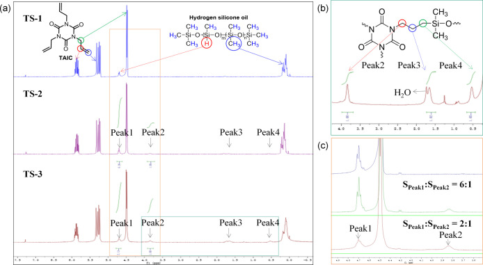
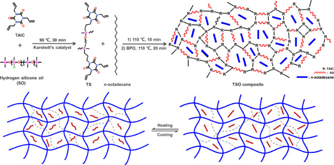
A series of TSO composites were prepared by an in situ polymerization method, and the corresponding schematic illustration is presented in Figure 1. All correlative samples were separately detected to investigate the reaction process and characterize the structure of TSO. The reaction process was monitored by 1H NMR measurements to give more convincing mechanism explanation and to further determine the specific structure of the original intermediate. The 1H NMR spectra of TS-1, TS-2, and TS-3 were analyzed and presented in Figure 2 and the corresponding separate spectra of the substrates and products are listed in Figures S2–S6. Compared with the spectrum of TS-1, a new set of peaks appeared in the spectrum of TS-2, marked as Peak2, Peak3, and Peak4, respectively. Apparently, with the Peak1 coming from Si–H as the reference, the intensity of these new peaks gradually increased along with higher reaction temperature. It is obvious that the hydrosilylation reaction has occurred between TAIC and SO because the position of the three emerging peaks and the ratio of the peaks’ area completely match the additive product of −CH=CH2 and Si–H segments. Meanwhile, the remaining prominent peaks of H signals ranging from δ = 5.0 to 6.5 in the spectrum of TS-3 were attributed to −the CH=CH2 groups of TAIC, which participated in radical polymerization to form the supporting matrix subsequently.
Figure 1.
Schematic illustration for the preparation of TSO composites.
Figure 2.
(a) 1H NMR spectra of TS-1, TS-2, and TS-3, (b) detailed 1H NMR spectra of TS-3, and (c) magnified image of (a).
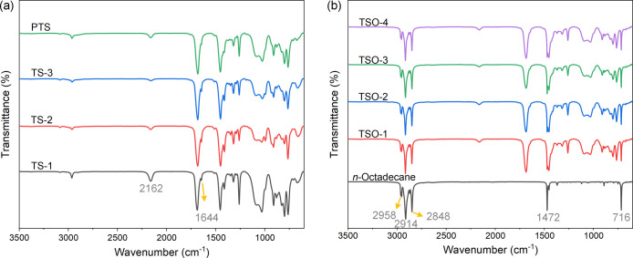
In addition, the FT-IR spectra of TS-1, TS-2, TS-3, and PTS are presented in Figure 3a, and specific states of these samples are shown in the Supporting Information. For TS-1, the absorption peaks at 1682, 1644, and 1410 cm–1 come from TAIC (Figure S7) and correspond to the C=O, C=C, and C–N groups, respectively.23,27 The characteristic absorption peaks at 2162 and 1030 cm–1 come from SO (Figure S7) and correspond to the Si–H and Si–O–Si groups, respectively.28,29 For TS-2 and TS-3, the absorption peak at 2162 cm–1 became increasingly weak as the reaction proceeded. In addition, the system changed from being a colorless low viscosity liquid to a milky white high viscosity paste (Figure S8). The above results proved that hydrosilylation reaction had occurred between TAIC and SO. The absorption peak of PTS at 1644 cm–1 disappeared, and the sample became solid particles (Figure S8), indicating that the C=C groups of the remaining TAIC reacted to form a 3D cross-linked network structure (Figure 1). The test results show that the skeleton material with a three-dimensional network structure has been successfully prepared.
Figure 3.
FT-IR spectra of (a) TS-1, TS-2, TS-3, and PTS and (b) n-octadecane and TSO composites.
Figure 3b shows the FT-IR spectra of n-octadecane and TSO composites. For the pristine n-octadecane, the absorbance bands appeared at 2958, 2914, and 2848 cm–1, caused by −CH3 asymmetric and symmetric stretching bands.30,31 The absorbance bands at 1472 and 716 cm–1 were attributed to the symmetric deformation and in-plane rocking vibration of −CH3. Likewise, the TSO composites exhibited characteristic peaks at the same positions as those observed from n-octadecane and PTS. Except for the peak intensity that changed slightly with different proportions of n-octadecane, the characteristic peak had no appreciable changes or shifts. The results indicate that n-octadecane is merely bound by PTS network structure without any chemical reaction.
2.2. Crystallization Properties of the TSO Composites
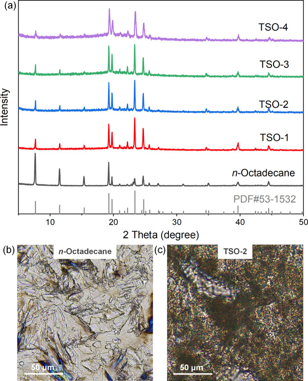
Figure 4a shows the XRD profiles of n-octadecane and TSO composites. The XRD pattern of PTS, as shown in Figure S9, suggested that PTS was an amorphous polymer. A series of strong diffraction peaks at 7.7, 11.5, 15.4, 19.3, 19.8, 23.4, and 24.8° could be observed clearly, which corresponded to the lattice planes of (002), (003), (004), (010), (011), (102), and (111) of n-octadecane, respectively. The TSO composites have diffraction patterns similar to the standard PDF card of n-octadecane, indicating that n-octadecane retains its original crystal type after in situ reaction. However, the relative intensity of the diffraction peaks of pure n-octadecane and TSO composites changed obviously. The results showed that the crystallization of n-octadecane in TSO composites was restricted in a finite inner space of the skeleton structures, and n-octadecane in TSO composites existed in the form of tiny particles, which lead to a great similarity of the XRD patterns of TSO and PDF card of pure n-octadecane.
Figure 4.
(a) XRD patterns of n-octadecane and TSO composites; POM micrographs of (b) n-octadecane and (c) TSO-2 at room temperature.
The crystallization properties of n-octadecane and TSO-2 were further characterized by polarized optical microscopy (POM), and the micrographs are shown in Figure 4b,c. For pure n-octadecane, the crystal was fibrous and had excellent crystallization properties. For TSO-2, the continuous black network skeleton structure showed a phase separation structure, indicating that n-octadecane was arrested by the network formation. In addition, the n-octadecane crystal in composites was subdivided and evenly dispersed, and the crystallization ability was much lower than that of pure n-octadecane, attributed to the free growth of n-octadecane crystal inhibited by the skeleton structure.32 The results above show that PTS can be used as a shape-setting material for paraffin PCMs.
2.3. Shape-Stabilized Properties of the TSO Composites
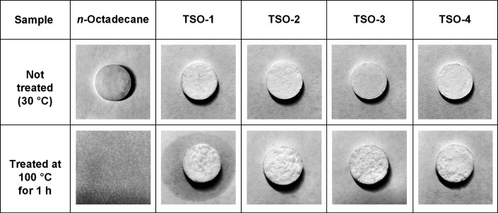
The shape-stabilized properties of n-octadecane and TSO composites were recorded by a digital camera to investigate the practicability. As can be seen in Figure 5, the samples showed different thermal shape stabilities at the same temperature. Pure n-octadecane transformed into liquid quickly and completely at 100 °C. However, the composites had no obvious change at the macro level and retained their shapes during the whole test process. The shape stability of the composites is due to the space network structure of PTS, which can effectively restrict the free movement of n-octadecane chains and prevent the melting n-octadecane from leaking when the temperature is higher than its melting point. However, a small quantity of n-octadecane leaked from TSO-1, which exceeded the limit of PTS skeleton’s carrying capacity. In brief, the TSO composites with shape stability overcome the disadvantage of serious leakage, superior to traditional solid–liquid PCMs, and show better practicability in application.
Figure 5.
Pictures of n-octadecane and TSO composites during the thermal shape stability test.
2.4. Morphologies of the TSO Composites
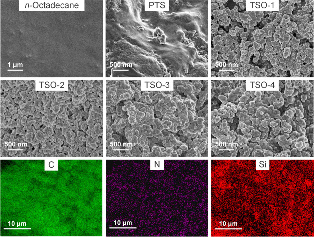
The surface morphologies of n-octadecane, PTS, and TSO composites are shown in Figure 6. n-Octadecane exhibited a uniform and smooth morphology, and PTS exhibited an irregular and rough morphology. For TSO composites, all samples had a similar uniform morphology. Moreover, the uniform distribution of C, N, and Si elements in TSO-2 could be observed in Figure 6, which showed that n-octadecane had good compatibility and dispersibility in the PTS matrix. In addition, with the increase of the PTS content, the connective island structure on the surface of the composite changed into a spherical convex structure. The results show that when the mass fraction of n-octadecane is high (TSO-1), the n-octadecane chains could not be completely restricted in the cross-linked network structure. Therefore, n-octadecane in TSO-1 will leak under high temperature after a long time, as seen in Figure 5.
Figure 6.
SEM images of n-octadecane, PTS, TSO-1, TSO-2, TSO-3, and TSO-4 and the element mappings of TSO-2.
2.5. Thermal Energy Storage Properties of the TSO Composites
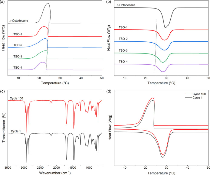
The differential scanning calorimetry (DSC) curves of n-octadecane and TSO composites are presented in Figure 7a,b. The corresponding parameters including initial crystallization temperature (Toc), crystallization peak temperature (Tc), crystallization enthalpy (ΔHc), initial melting temperature (Tom), melting peak temperature (Tm), and melting enthalpy (ΔHm) are summarized in Table 1. Pure n-octadecane exhibited suitable phase transition temperature, with Tc of 24.25 °C and Tm of 29.37 °C, and higher phase transition enthalpy, with ΔHc of 227.93 J/g and ΔHm of 228.21 J/g. When n-octadecane was incorporated into the PTS network, Toc and Tom of the composites decreased linearly with the decrease of the n-octadecane content. It may be explained by the following reasons. The high thermal conductivity of the PTS skeleton promotes the rapid melting of n-octadecane in the heating process.33,34 The thermal conductivity test data are shown in Table S1. However, the interactions between n-octadecane chains and PTS are detrimental to the crystallization of n-octadecane in the cooling process. Using the simple mixing theory, the relative enthalpy efficiency (η) is calculated via the following equation35,36
where  and
and  are
the melting enthalpies of pure n-octadecane and composites,
respectively. ω is the
mass fraction of n-octadecane in the composites,
which is calculated according to the weight of added materials. By
calculation, the η values of composites are less than 100%.
This is mainly due to the confinement effect of the supporting framework,
which would impart restriction to the movement of n-octadecane chains through the intermolecular interaction between n-octadecane and PTS.37−40
Figure 7.
DSC curves of n-octadecane and TSO composites during the (a) cooling and (b) heating processes; (c) FT-IR spectra and (d) DSC curves of TSO-2 before and after the thermal cycling test.
Table 1. DSC Data of n-Octadecane and TSO Compositesa.
| cooling |
heating |
||||||||
|---|---|---|---|---|---|---|---|---|---|
| sample | ω (%) | Tc (°C) | Toc (°C) | ΔHc (J/g) | Tm (°C) | Tom (°C) | ΔHm (J/g) | ΔHm* (J/g) | η (%) |
| n-octadecane | 24.25 | 25.17 | 227.93 | 29.37 | 25.85 | 228.21 | |||
| TSO-1 | 62.32 | 22.32 | 24.20 | 137.52 | 29.04 | 24.93 | 137.99 | 142.22 | 97.03 |
| TSO-2 | 58.75 | 22.89 | 23.91 | 129.81 | 29.05 | 24.71 | 130.35 | 134.08 | 97.22 |
| TSO-3 | 54.40 | 23.11 | 23.64 | 119.95 | 28.30 | 24.51 | 120.65 | 124.14 | 97.19 |
| TSO-4 | 48.94 | 21.74 | 23.36 | 108.03 | 28.29 | 24.30 | 108.78 | 111.70 | 97.39 |
Note: ΔHm* =  .
.
2.6. Thermal Reliability and Structural Stability of the TSO Composites
The thermal properties of TSO-2 before and after the thermal cycling test were characterized by FT-IR and DSC, as demonstrated in Figure 7c,d. The overlapping curves of FT-IR spectra indicated that the thermal cycling test had almost no influence on the chemical structure of the composite. According to Table 2, it was noticeable that insignificant changes occurred to the phase change temperatures and enthalpies after 100 thermal cycles. The phase change temperatures changed by 0.03 and 0.16 °C, and the phase change enthalpies decreased by 0.97 and 0.94%, respectively, after the thermal cycling test. In summary, the TSO composites have superior thermal reliability, which can be used as thermal storage materials in practical applications.
Table 2. DSC Data of TSO-2 before and after the Thermal Cycling Test.
| cooling |
heating |
|||||
|---|---|---|---|---|---|---|
| sample | Tc (°C) | Toc (°C) | ΔHc (J/g) | Tm (°C) | Tom (°C) | ΔHm (J/g) |
| 1 cycle | 22.89 | 23.91 | 129.81 | 29.05 | 24.71 | 130.35 |
| 100 cycles | 22.92 | 23.90 | 128.55 | 29.21 | 24.96 | 129.13 |
2.7. Thermal Stability of the TSO Composites
The TGA curves in Figure 8a,b illustrate the thermal stability of n-octadecane, PTS, and TSO composites, and the corresponding TGA data are listed in Table 3. The corresponding DTG curves are shown in Figure 8c to determine the maximum rate of weight loss of the samples. Pure n-octadecane exhibited the one-step thermal degradation process, in which the temperature at the beginning of degradation was 140.22 °C, and the residue after decomposition was only 1.32%. PTS exhibited a two-step thermal degradation process. The minor weight loss was caused by the vaporization of some volatile components, and the major weight loss that occurred from 436.84 to 722.75 °C indicated the higher thermal stability. The degradation of the TSO composites was also a two-step process. The first degradation step between 152 and 272 °C can be attributed to n-octadecane. The decomposition temperature was slightly higher than that of n-octadecane, indicating that the thermal stability of the material can be improved through the mutual winding of the n-octadecane chain segment and the skeleton structure. In addition, the residual amount of the composites after the first stage was a little higher than the theoretical value, which might be related to the part of the carbonized n-octadecane bound by the PTS network skeleton. The second degradation stage observed at around 431–669 °C can be ascribed to the degradation of the polymer chains, as shown in the Supporting Information. The results above indicate that the composites have excellent thermal stability under high temperature conditions.
Figure 8.
(a) TGA curves, (b) detailed TGA curves at 100–220 °C, and (c) DTG curves of n-octadecane, PTS, and TSO composites.
Table 3. Characteristic Temperatures of TGA Curves of n-Octadecane, PTS, and TSO Composites.
| sample | decomposition temperature (°C) | residual quantity (%) |
|---|---|---|
| n-octadecane | 140.22–281.05 | 1.32 |
| PTS | 50.00–219.49 | 95.77 |
| 436.84–722.75 | 27.84 | |
| TSO-1 | 152.64–267.83 | 41.13 |
| 431.96–667.24 | 9.38 | |
| TSO-2 | 153.09–269.79 | 43.71 |
| 432.42–668.13 | 11.29 | |
| TSO-3 | 153.26–269.98 | 47.60 |
| 443.08–667.90 | 10.04 | |
| TSO-4 | 153.34–271.23 | 52.34 |
| 432.73–668.62 | 10.67 |
3. Conclusions
A class of novel phase change TSO composites has been first synthesized by an in situ reaction, in which n-octadecane was selected as a PCM, and the original TS intermediate functioned as a supporting material by self-crossl-inking. The three-dimensional PTS network effectively prevented the leakage of n-octadecane during its phase transition, and the high-strength cross-linked skeleton also contributed to its great dimensional stability. Therefore, the TSO composites remained solid even when heated at 100 °C for a long time and still showed excellent phase change properties, moderate phase transition temperatures below 30 °C, and high latent enthalpies of around 130 J/g. Moreover, they exhibited excellent thermal reliability due to the fact that insignificant change occurred to the phase change temperatures and enthalpies after 100 thermal cycles. Thus, shape-stabilized TSO composites, prepared through the practical and economical strategy, are promising PCMs for thermal energy storage and thermal management.
4. Materials and Methods
4.1. Materials
Triallyl isocyanurate (TAIC) was purchased from D-Chem Ltd. Hydrogen silicone oil (SO, 41.7 mPa·s, Si–H: 0.8 wt %) was supplied by Shandong Dayi Chemical Co., Ltd. n-Octadecane was purchased from Shanghai Macklin Biochemical Co., Ltd. Benzoyl peroxide (BPO) was purchased from Sinopharm Chemical Reagent Co., Ltd. Karstedt diluent (5000 ppm) was supplied by Shanghai Borje New Materials Co., Ltd. All substances were used as received without any further purification.
4.2. Preparation of PTS
In order to explore, 11 g TAIC and 5 g SO were mixed uniformly with stirring in a three-neck round-bottom flask. At this point, the sample is denoted as TS-1. Then, Karstedt diluent (0.3% of the mixture weight) was added into the flask, and the mixture was stirred at 90 °C for 30 min (TS-2). Subsequently, the temperature was raised to 110 °C and kept for 10 min (TS-3). Finally, BPO (2% of the gross weight) was added into the mixture, which continued to be stirred at 110 °C for 20 min to obtain PTS.
4.3. Preparation of the TSO Composites
11 g TAIC and 5 g SO were mixed uniformly with stirring in a 100 mL three-neck round-bottom flask, and the molar ratio of TAIC to hydrogen of SO was 1.1:1. Then, Karstedt diluent (0.3% of the mixture weight) was added into the flask, and the mixture was stirred at 90 °C for 30 min. Subsequently, n-octadecane was added, and the temperature was raised to 110 °C and kept for 10 min. Finally, BPO (2% of the gross weight) was added into the mixture, which continued to be stirred for 20 min. The white powder obtained in the flask was the TAIC-SO/n-octadecane (TSO) composites. The synthesized composites, with the content of n-octadecane being 28, 24, 20, and 16 g, were marked as TSO-1, TSO-2, TSO-3, and TSO-4, respectively.
4.4. Characterizations
The chemical compositions of the samples were analyzed by Fourier transform infrared spectroscopy (FT-IR, PerkinElmer, USA) in ATR geometry using a diamond crystal. The 1H NMR spectra were recorded on a Bruker AscendTM 400 spectrometer (400 MHz). Powder X-ray diffraction (XRD) was performed on a Rigaku SmartLab 3kW X-ray diffractometer with Cu Kα radiation (λ = 1.54056 Å, 40 kV, 30 mA, 10° min–1). Sample powders were filled in the sample cell directly without any treatment, and excess powders were scraped off to ensure that height of the specimen was equal to the surface of the sample cell. There is no compression in the sample preparation process. The degree of crystallinity of the samples at room temperature was observed by POM on Olympus BX53M. The morphology of the samples was examined by scanning electron microscopy (SEM, ZEISS GeminiSEM 300), and the composition was determined by energy-dispersive X-ray spectrometry (EDXS) using the accessory manufactured by Oxford Instruments. Larger particles for SEM and EDS were directly sticked on the conductive adhesive without any treatment. The latent heat was measured via DSC using the TA Instruments Q20 differential calorimeter at a scanning rate of 5 °C min–1. The thermal conductivity of the samples was measured by using a thermal conductivity testing instrument (LFA 457, NETZSCH). TGA was performed on a simultaneous thermal analyzer (ZCT-B TG/DTA) at a heating rate of 10 °C min–1.
Acknowledgments
The work was jointly supported by Guangdong Provincial Natural Science Foundation no. 2020A1515110831, Guangdong Special Support Program no. 2017TX04C096, Shenzhen Science and Technology Research Funding no. JCYJ20180507182047316, and Shenzhen Science and Technology Research Funding no. RCJC20200714114435 061.
Glossary
Nomenclature2-col
- TAIC
triallyl isocyanurate
- SO
hydrogen silicone oil
- TS-1
mixture of TAIC and SO, and the mass ratio is 2.2:1
- TS-2
prepolymer of TAIC and SO (TS-1, Karstedt diluent, 90 °C, 30 min)
- TS-3
prepolymer of TAIC and SO (TS-2, 110 °C, 10 min)
- PTS
polymer of TAIC and SO
- TSO
PTS/n-octadecane composites
- TSO-1
the mass ratio of PTS to n-octadecane is 1:1.75
- TSO-2
the mass ratio of PTS to n-octadecane is 1:1.5
- TSO-3
the mass ratio of PTS to n-octadecane is 1:1.25
- TSO-4
the mass ratio of PTS to n-octadecane is 1:1
Supporting Information Available
The Supporting Information is available free of charge at https://pubs.acs.org/doi/10.1021/acsomega.2c00604.
Preparation processes of TO; macrographs of TAIC, SO, TO, TS, and PTS; FT-IR spectra of SO and TAIC; 1H NMR spectra of TAIC, SO, TS-1, TS-2, and TS-3; XRD pattern of PTS; elemental mappings of TSO-2; and thermal conductivity of PTS skeleton and n-octadecane (PDF)
Author Contributions
§ X.C. and X.H. contributed equally.
The authors declare no competing financial interest.
Supplementary Material
References
- Atinafu D. G.; Yun B. Y.; Yang S.; Yuk H.; Wi S.; Kim S. Structurally Advanced Hybrid Support Composite Phase Change Materials: Architectural Synergy. Energy Storage Mater. 2021, 42, 164–184. 10.1016/j.ensm.2021.07.022. [DOI] [Google Scholar]
- Shi J.; Qin M.; Aftab W.; Zou R. Flexible Phase Change Materials for Thermal Energy Storage. Energy Storage Mater. 2021, 41, 321–342. 10.1016/j.ensm.2021.05.048. [DOI] [Google Scholar]
- Zeinelabdein R.; Omer S.; Gan G. Critical Review of Latent Heat Storage Systems for Free Cooling in Buildings. Renew. Sustain. Energy Rev. 2018, 82, 2843–2868. 10.1016/j.rser.2017.10.046. [DOI] [Google Scholar]
- Deng Y.; Li J.; Deng Y.; Nian H.; Jiang H. Supercooling Suppression and Thermal Conductivity Enhancement of Na2HPO4·12H2O/Expanded Vermiculite Form-Stable Composite Phase Change Materials with Alumina for Heat Storage. ACS Sustainable Chem. Eng. 2018, 6, 6792–6801. 10.1021/acssuschemeng.8b00631. [DOI] [Google Scholar]
- Huang H.; Shi T.; He R.; Wang J.; Chu P. K.; Yu X.-F. Phase-Changing Microcapsules Incorporated with Black Phosphorus for Efficient Solar Energy Storage. Adv. Sci. 2020, 7, 2000602. 10.1002/advs.202000602. [DOI] [PMC free article] [PubMed] [Google Scholar]
- Sood D.; Das D.; Fatima Ali S.; Rakshit D. Numerical Analysis of An Automobile Cabin Thermal Management Using Passive Phase Change Material. Therm. Sci. Eng. Prog. 2021, 25, 100870. 10.1016/j.tsep.2021.100870. [DOI] [Google Scholar]
- Qin P.; Liao M.; Zhang D.; Liu Y.; Sun J.; Wang Q. Experimental and Numerical Study on a Novel Hybrid Battery Thermal Management System Integrated Forced-Air Convection and Phase Change Material. Energy Convers. Manage. 2019, 195, 1371–1381. 10.1016/j.enconman.2019.05.084. [DOI] [Google Scholar]
- Naveenkumar R.; Ravichandran M.; Mohanavel V.; Karthick A.; Aswin L. S. R. L.; Priyanka S. S. H.; Kumar S. K.; Kumar S. P. Review on Phase Change Materials for Solar Energy Storage Applications. Environ. Sci. Pollut. Res. 2022, 29, 9491–9532. 10.1007/s11356-021-17152-8. [DOI] [PubMed] [Google Scholar]
- Katekar V. P.; Deshmukh S. S. A Review of the Use of Phase Change Materials on Performance of Solar Stills. J. Energy Storage 2020, 30, 101398. 10.1016/j.est.2020.101398. [DOI] [Google Scholar]
- Zhang Y.; Umair M. M.; Zhang S.; Tang B. Phase Change Materials for Electron-Triggered Energy Conversion and Storage: A Review. J. Mater. Chem. A 2019, 7, 22218–22228. 10.1039/c9ta06678k. [DOI] [Google Scholar]
- Liu P.; Gu X.; Bian L.; Cheng X.; Peng L.; He H. Thermal Properties and Enhanced Thermal Conductivity of Capric Acid/Diatomite/Carbon Nanotube Composites as Form-Stable Phase Change Materials for Thermal Energy Storage. ACS Omega 2019, 4, 2964–2972. 10.1021/acsomega.8b03130. [DOI] [Google Scholar]
- Chen C.; Wang L.; Huang Y. Electrospun Phase Change Fibers Based on Polyethylene Glycol/Cellulose Acetate Blends. Appl. Energy 2011, 88, 3133–3139. 10.1016/j.apenergy.2011.02.026. [DOI] [Google Scholar]
- Alehosseini E.; Jafari S. M. Nanoencapsulation of Phase Change Materials (Pcms) and Their Applications in Various Fields for Energy Storage and Management. Adv. Colloid Interface Sci. 2020, 283, 102226. 10.1016/j.cis.2020.102226. [DOI] [PubMed] [Google Scholar]
- Serrano A.; Dauvergne J.-L.; Doppiu S.; Palomo Del Barrio E. Neopentyl Glycol as Active Supporting Media in Shape-Stabilized PCMs. Materials 2019, 12, 3169. 10.3390/ma12193169. [DOI] [PMC free article] [PubMed] [Google Scholar]
- Sarı A.; Alkan C.; Bicer A. Development, Characterization, and Latent Heat Thermal Energy Storage Properties of Neopentyl Glycol-Fatty Acid Esters as New Solid–Liquid PCMs. Ind. Eng. Chem. Res. 2013, 52, 18269–18275. 10.1021/ie403039n. [DOI] [Google Scholar]
- Zhang X.; Lin Q.; Luo H.; Luo S. Three-Dimensional Graphitic Hierarchical Porous Carbon/Stearic Acid Composite as Shape-Stabilized Phase Change Material for Thermal Energy Storage. Appl. Energy 2020, 260, 114278. 10.1016/j.apenergy.2019.114278. [DOI] [Google Scholar]
- Huang X.; Zhu C.; Lin Y.; Fang G. Thermal Properties and Applications of Microencapsulated PCM for Thermal Energy Storage: A Review. Appl. Therm. Eng. 2019, 147, 841–855. 10.1016/j.applthermaleng.2018.11.007. [DOI] [Google Scholar]
- Liu H.; Wang X.; Wu D. Innovative Design of Microencapsulated Phase Change Materials for Thermal Energy Storage and Versatile Applications: A Review. Sustain. Energy Fuels 2019, 3, 1091–1149. 10.1039/c9se00019d. [DOI] [Google Scholar]
- Zhang S.; Feng D.; Shi L.; Wang L.; Jin Y.; Tian L.; Li Z.; Wang G.; Zhao L.; Yan Y. A Review of Phase Change Heat Transfer in Shape-Stabilized Phase Change Materials (ss-Pcms) Based on Porous Supports for Thermal Energy Storage. Renew. Sustain. Energy Rev. 2021, 135, 110127. 10.1016/j.rser.2020.110127. [DOI] [Google Scholar]
- Umair M. M.; Zhang Y.; Iqbal K.; Zhang S.; Tang B. Novel Strategies and Supporting Materials Applied to Shape-Stabilize Organic Phase Change Materials for Thermal Energy Storage–A Review. Appl. Energy 2019, 235, 846–873. 10.1016/j.apenergy.2018.11.017. [DOI] [Google Scholar]
- Abdeali G.; Bahramian A. R.; Abdollahi M. Review on Nanostructure Supporting Material Strategies in Shape-stabilized Phase Change Materials. J. Energy Storage 2020, 29, 101299. 10.1016/j.est.2020.101299. [DOI] [Google Scholar]
- Huang X.; Guo J.; An Q.; Gong X.; Gong Y.; Zhang S. Preparation and Characterization of Di-Hexadecanol Maleic/Triallyl Isocyanurate Cross-Linked Copolymer as Solid–Solid Phase Change Materials. J. Appl. Polym. Sci. 2016, 133, 44065. 10.1002/app.44065. [DOI] [Google Scholar]
- Huang X.; Guo J.; He J.; Gong Y.; Wang D.; Song Z. Novel Phase Change Materials Based on Fatty Acid Eutectics and Triallyl Isocyanurate Composites for Thermal Energy Storage. J. Appl. Polym. Sci. 2017, 134, 44866. 10.1002/app.44866. [DOI] [Google Scholar]
- Huang X.; Guo J.; Gong Y.; Li S.; Mu S.; Zhang S. In-situ Preparation of a Shape Stable Phase Change Material. Renewable Energy 2017, 108, 244–249. 10.1016/j.renene.2017.02.083. [DOI] [Google Scholar]
- Zhang Y.; Wang L.; Tang B.; Lu R.; Zhang S. Form-stable Phase Change Materials with High Phase Change Enthalpy from the Composite of Paraffin and Cross-Linking Phase Change Structure. Appl. Energy 2016, 184, 241–246. 10.1016/j.apenergy.2016.10.021. [DOI] [Google Scholar]
- Sarier N.; Onder E. Organic Phase Change Materials and Their Textile Applications: An Overview. Thermochim. Acta 2012, 540, 7–60. 10.1016/j.tca.2012.04.013. [DOI] [Google Scholar]
- Yang S.-l.; Wu Z.-H.; Yang W.; Yang M.-B. Thermal and Mechanical Properties of Chemical Crosslinked Polylactide (PLA). Polym. Test. 2008, 27, 957–963. 10.1016/j.polymertesting.2008.08.009. [DOI] [Google Scholar]
- Camino G.; Lomakin S. M.; Lageard M. Thermal Polydimethylsiloxane Degradation. Part 2. The Degradation Mechanisms. Polymer 2002, 43, 2011–2015. 10.1016/s0032-3861(01)00785-6. [DOI] [Google Scholar]
- Li Y.-f. S.; Zang C.-g.; Zhang Y.-l. Effect of The Structure of Hydrogen-Containing Silicone Oil on The Properties of Silicone Rubber. Mater. Chem. Phys. 2020, 248, 122734. 10.1016/j.matchemphys.2020.122734. [DOI] [Google Scholar]
- Zhao L.; Li M.; Yu Q.; Zhang Y.; Li G.; Huang Y. Improving the Thermal Performance of Novel Low-Temperature Phase Change Materials Through the Configuration of 1-Dodecanol-Tetradecane Nanofluids/Expanded Graphite Composites. J. Mol. Liq. 2021, 322, 114948. 10.1016/j.molliq.2020.114948. [DOI] [Google Scholar]
- Mert H. H.; Kekevi̇ B.; Mert E. H.; Mert M. S. Development of Composite Phase Change Materials Based on N-Tetradecane and Β-Myrcene Based Foams for Cold Thermal Energy Storage Applications. Thermochim. Acta 2022, 707, 179116. 10.1016/j.tca.2021.179116. [DOI] [Google Scholar]
- Cheng M.; Hu J.; Xia J.; Liu Q.; Wei T.; Ling Y.; Li W.; Liu B. One-step In-Situ Green Synthesis of Cellulose Nanocrystal Aerogel Based Shape Stable Phase Change Material. Chem. Eng. J. 2022, 431, 133935. 10.1016/j.cej.2021.133935. [DOI] [Google Scholar]
- Yu S.; Wang X.; Wu D. Microencapsulation of n-Octadecane Phase Change Material with Calcium Carbonate Shell for Enhancement of Thermal Conductivity and Serving Durability: Synthesis, Microstructure, and Performance Evaluation. Appl. Energy 2014, 114, 632–643. 10.1016/j.apenergy.2013.10.029. [DOI] [Google Scholar]
- Liu Y.; Jiang S.; Yan W.; Qin J.; He M.; Qin S.; Yu J. Enhanced Thermal Property and Anti-Moisture Absorption of PA6/P (N-(4-Carboxyphenyl)Maleimide-Alt-Triallyl Isocyanurate) Composites Based on Solid-State Interfacial Reaction. J. Mater. Res. Technol. 2020, 9, 11291–11302. 10.1016/j.jmrt.2020.07.103. [DOI] [Google Scholar]
- Zhou Y.; Sheng D.; Liu X.; Lin C.; Ji F.; Dong L.; Xu S.; Yang Y. Synthesis and Properties of Crosslinking Halloysite Nanotubes/Polyurethane-Based Solid-Solid Phase Change Materials. Sol. Energy Mater. Sol. Cells 2018, 174, 84–93. 10.1016/j.solmat.2017.08.031. [DOI] [Google Scholar]
- Qian Y.; Han N.; Zhang Z.; Cao R.; Tan L.; Li W.; Zhang X. Enhanced Thermal-to-Flexible Phase Change Materials Based on Cellulose/Modified Graphene Composites for Thermal Management of Solar Energy. ACS Appl. Mater. Interfaces 2019, 11, 45832–45843. 10.1021/acsami.9b18543. [DOI] [PubMed] [Google Scholar]
- Liu L.; Zou X.; Wang Y.; Zhou W.; Shi J.; Ye Y.; Zhao Y.; Zhang H.; Yu Y.; Guo J.; et al. Phase Change and Aerogel Dual Functionalized Composites Materials with Double Network Structure Through One-Step Preparation of Polyacrylamide/Calcium Alginate/Polyethylene Glycol. Polymer 2021, 223, 123710. 10.1016/j.polymer.2021.123710. [DOI] [Google Scholar]
- Wang Y.; Qiu Z.; Lang Z.; Xie Y.; Xiao Z.; Wang H.; Liang D.; Li J.; Zhang K. Multifunctional Reversible Self-Assembled Structures of Cellulose-Derived Phase-Change Nanocrystals. Adv. Mater. 2021, 33, 2005263. 10.1002/adma.202005263. [DOI] [PMC free article] [PubMed] [Google Scholar]
- Gao H.; Bo L.; Liu P.; Chen D.; Li A.; Ou Y.; Dong C.; Wang J.; Chen X.; Hou C.; et al. Ambient Pressure Dried Flexible Silica Aerogel for Construction of Monolithic Shape-Stabilized Phase Change Materials. Sol. Energy Mater. Sol. Cells 2019, 201, 110122. 10.1016/j.solmat.2019.110122. [DOI] [Google Scholar]
- Zhou L.; Tang L.-S.; Tao X.-F.; Yang J.; Yang M.-B.; Yang W. Facile Fabrication of Shape-Stabilized Polyethylene Glycol/Cellulose Nanocrystal Phase Change Materials Based on Thiol-Ene Click Chemistry and Solvent Exchange. Chem. Eng. J. 2020, 396, 125206. 10.1016/j.cej.2020.125206. [DOI] [Google Scholar]
Associated Data
This section collects any data citations, data availability statements, or supplementary materials included in this article.


