

Abstract
Study Design:
Observational study.
Objective:
This study was aimed at investigating the reliability of anterior pelvic plane (APP) as an anatomical reference plane for assessing the patients’ pelvic incidence in patients with ankylosing spondylitis kyphosis deformity.
Methods:
The globe kyphosis (GK), lumber lordosis (LL), thoracolumbar kyphosis (TLK), thoracic kyphosis (TK), anatomical cervical 7 sacrum angle (aC7SA), and cervical 7 sacrum angle (C7SA) were measured on full-length spine radiography imagines. The pelvic incidence (PI), anatomical pelvic tilt (aPT), and anatomical sacral slope (aSS) were measured on the pelvic synthesized 2D lateral radiography imagines. Because the angle between APP and vertical line was about 4°, Angle1 and tPT were calculated using the following formulas: Angle1 = aC7SA − 4; PT = aPT + 4. According to the study conducted by Vialle, traditional PT (tPT) was calculated using the following widely accepted formula: tPT = PI * 0.37 − 7. Measured PT (mPT) was also measured on the full-length spine radiography imagines.
Results:
The data analysis showed that PI, mPT, aSS, aPT, and APPA were 50.83 ± 13.44°, 32.52 ± 4.64°, 41.36 ± 9.46°, 8.56 ± 6.80°, and 23.95 ± 5.17°, respectively. There was no significant difference between the PT and tPT (12.56 ± 6.80, 11.49 ± 4.73; P = .152). So, the results demonstrated that the PT could play the equivalent effect as tPT did for making surgical plans in patients with kyphosis deformity.
Conclusion:
The pelvic anatomical reference plane had potential to be used in assessing the patients’ ideal pelvic incident without the influence of spinal sagittal deformity. The aPT+4 may represent patients’ postoperative ideal PT.
Keywords: anterior pelvic plane, pelvic incident
Introduction
Since Legaye et al described pelvic incidence (PI), 1 the role of the pelvis and pelvic parameters in spinal diseases have been studied increasingly.2-5 It has been demonstrated that good functional and clinical outcomes are significantly associated with the restoration of proper sagittal spinopelvic alignment. 6 PI is an important anatomic parameter that is highly individual and likely determines other pelvic parameters, such as the sacral slope and pelvic tilt (PT).1,3 In addition to PI, PT is also a critical pelvic parameter and can be considered an indicator of postural disorders in patients. 7 Changes in PT in patients with degenerative spine diseases are believed to be compensatory mechanisms of sagittal imbalance, and PT is associated with low back pain. 6 It has also been reported that PT is correlated with the health-related quality of life of adults with deformities. 8 PT plays an important role in the planning and execution of spine surgery, especially in patients with spinal deformities.9,10 Before surgery, the ideal PT needs to be determined to calculate the correction degree of surgery. However, for patients with spinal kyphosis, it is difficult to estimate the true PT because of compensatory mechanisms involving the lower extremities and pelvic rotation. Anatomical pelvic tilt (aPT) may be a useful parameter for guiding and planning surgery. Anatomical pelvic tilt is defined as the angle between the anterior pelvic plane (APP) and the line connecting the midpoint of the S1 endplate and the center of the femoral head.
The APP is commonly used by joint surgeons as an anatomical reference plane for preoperatively determining and postoperatively evaluating the orientation of the acetabular cup in total hip arthroplasty and is commonly considered the coronal plane of the pelvis.11-16 The APP is defined as the plane formed by the 2 anterior superior iliac spines and the pubic symphysis. 4 However, recently, some authors have reported that the APP is not the real coronal plane of the pelvis, and the angle between the APP and the vertical line (APPA) is approximately 4° when normal subjects are standing in a natural standing position. 17 The APPA is defined as the angle between the line connecting the midpoint of the 2 anterior superior iliac spines to the pubic symphysis and the vertical line on the lateral radiograph of the pelvis in the standing position. 4 In the present study, we hypothesized that we could assess patients’ ideal PT with respect to the APP, an anatomical reference plane, in patients with kyphotic deformities.
This study aimed to investigate the reliability of the APP as an anatomical reference plane for assessing pelvic parameters in patients with severe ankylosing spondylitis kyphotic deformities.
Methods and Materials
Patients
All the materials were used with the consent of the patients. The present research is subject to ethical standards that promote and ensure respect for all human subjects and protect their health and rights.
Preoperative 3-dimensional computed tomography (3D CT) scans of the full spine were routinely performed to determine the vertebral pedicle type for safe pedicle screw placement. Therefore, in the present study, the patients did not suffer from additional radioactivity exposure. All CT examinations were performed using a sliding gantry 40-slice CT scanner (Siemens Medical Solutions, Samatom Sensation Open). The slice thickness of the scans was 1.5 mm, which could guarantee accuracy and a low spatial resolution. The voltage of the X-ray tube was adjusted to 80 kV to reduce the amount of radiation.
Patients with AS kyphotic deformities who underwent pedicle subtraction osteotomy in our department were included. The inclusion criteria were as follows: (1) individuals diagnosed with ankylosing spondylitis (AS) according to the modified New York criteria 18 ; (2) adult patients with AS kyphosis deformities; (3) individuals who underwent preoperative 3D CT scans of the full spine; (4) individuals who underwent CT scans that included the full pelvis; and (5) individuals who underwent full-length spine radiography scans preoperatively.
The exclusion criteria were as follows: (1) individuals with CT scans or lateral full-length spine X-ray films that did not include the full pelvis; (2) patients who had pelvic trauma and a history of surgery; and (3) patients with congenital pelvic and spine diseases.
A total of 41 patients (38 males and 3 females) were eligible and were included in the present study. The average age of the patients was 46.2 years.
Radiographic Parameters
After the CT scans were recorded, we reconstructed the pelvic and full spine model and then synthesized 2D lateral radiography images using these models; all the pelvic models were projected to the sagittal plane (Figure 1).
Figure 1.
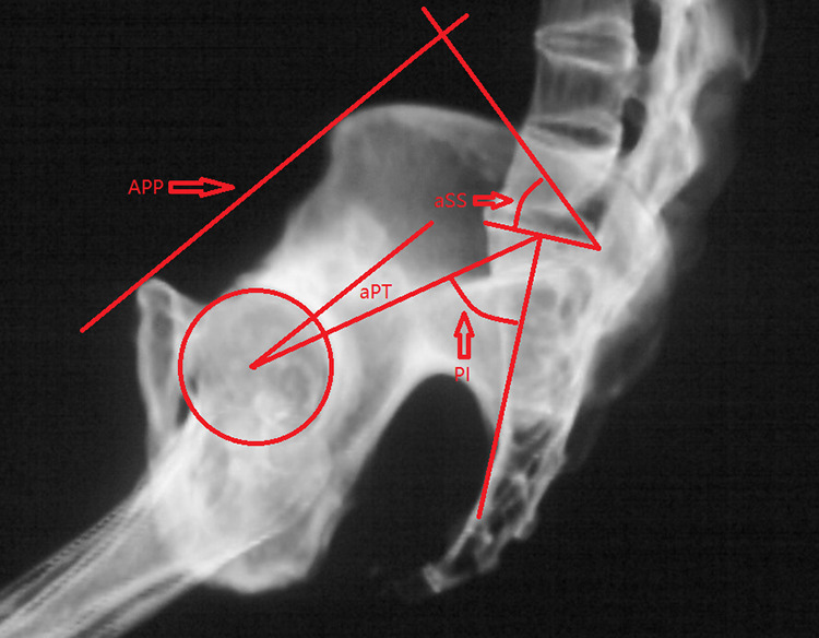
PI was measured as the angle between the line perpendicular to the sacral plate and the line through the middle point of the sacral plate and the center of the femoral head. aSS was the angle between the superior plate of S1 and the line perpendicular to the APP. aPT was the angle between the line connecting the sacral plate middle point and the center of the femoral head and the APP. Abbreviations: APP, pelvic anterior plane; aPT, anatomical PT; aSS, anatomical SS.
PI, measured pelvic tilt (mPT), anatomical PT (aPT), and anatomical SS (aSS) were also measured. PI was measured as the angle between the line perpendicular to the sacral plate and the line through the middle point of the sacral plate and the center of the femoral head. Measured PT was the angle formed by the line connecting the midpoint of the 2 femoral heads to the center of the sacral endplate and the vertical line in the patients’ standing radiographs. Anatomical SS was the angle between the superior plate of S1 and the line perpendicular to the APP. aPT was the angle between the line connecting the sacral plate middle point and the center of the femoral head and the APP.
The APP was the plane formed by the 2 anterior superior iliac spines and the pubic symphysis. 18 Because the angle between the APP and the vertical line was approximately 4°, 17 PT was calculated using the following formula: PT = aPT + 4. According to a study conducted by Vialle, tPT was calculated using the following widely accepted formula: tPT = PI * 0.37 − 7. 19 The APPA was defined as the angle between the line connecting the midpoint of the 2 anterior superior iliac spines to the pubic symphysis and the vertical line on the lateral radiograph of the pelvis in the standing position. 18 In theory, mPT minus the APPA plus 4° should be equal to tPT (tPT = mPT − APPA + 4).
The anatomical cervical 7 sacrum angle (aC7SA) was measured as the angle formed by the APP and the line connecting the center of the seventh cervical vertebra and the superior-posterior corner of the first sacrum vertebra. Angle1 was calculated using the following formula: Angle1 = aC7SA − 4. The C7SA was the angle formed by the C7 plumb line and the line passing through the center of C7 and the superior-posterior corner of the first sacrum vertebra (Figure 2).
Figure 2.
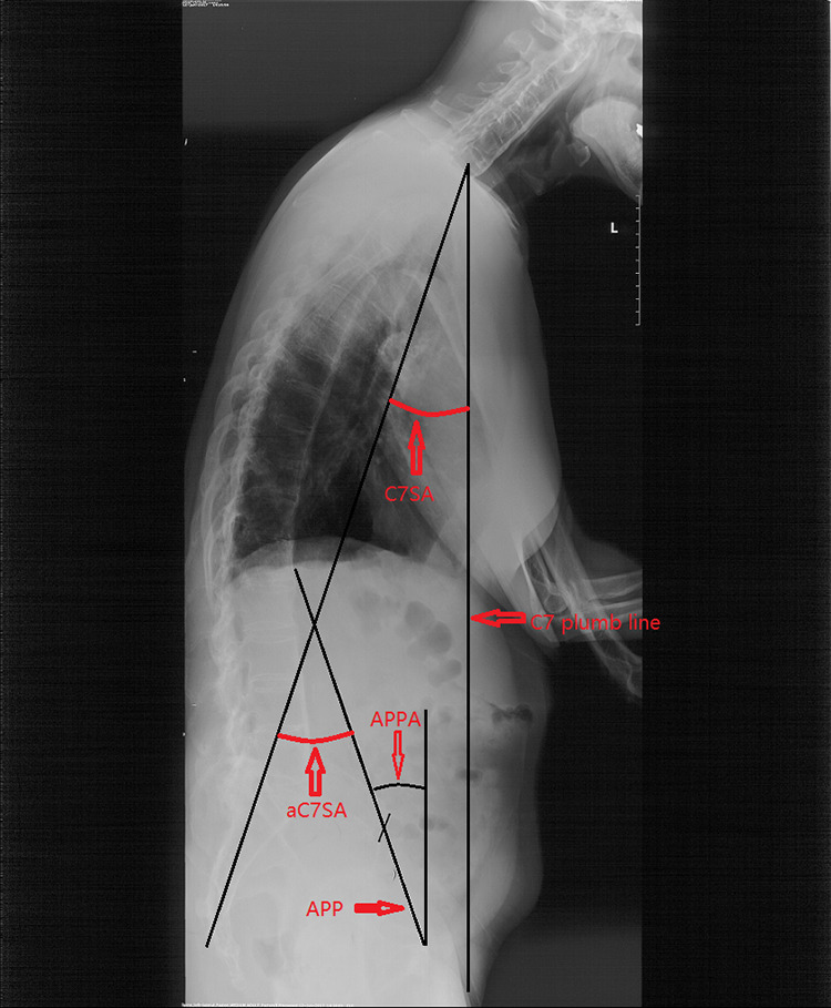
The anatomical cervical 7 sacrum angle (aC7SA) is measured as the angle formed by APP and the line through the seventh cervical vertebra center and the superior-posterior corner of the first sacrum vertebra. The C7SA was the angle formed by the C7 plumb line and the line through C7 center and superior-posterior corner of the first sacrum vertebra. APPA is defined as the angle between the line connecting the midpoint of both anterior superior iliac spines to the pubic symphysis and the vertical line of the lateral radiograph of the pelvis in patient’s standing position.
The globe kyphosis (GK), lumber lordosis (LL), thoracolumbar kyphosis (TLK), and thoracic kyphosis (TK) were measured. GK was measured from the superior end plate of the T5 thoracic vertebra to the superior end plate of the S1 vertebra. LL was defined as the Cobb angle between the 2 lines parallel to the superior endplate of L1 and the S1, respectively; TLK was defined as the Cobb angle between the 2 lines parallel to the superior endplate of T11 and the superior endplate of L2, respectively; TK was defined as the Cobb angle between the 2 lines parallel to the superior endplate of T5 and the inferior endplate of T12, respectively.
Statistical Analysis
Data analysis was performed using SPSS, version 16.0, for Windows. The paired-samples t test was used to assess the differences between the PT, mPT-APPA+4, and tPT. The Pearson test was performed to assess the correlations between Angle1 and GK, TK, TLK, and LL. The Pearson test was performed to assess the correlations between C7SA and GK, TK, TLK, and LL. A P value of less than .05 was considered to be significant in all analyses.
Results
The data analysis showed that PI, mPT, aSS, aPT and APPA were 50.83 ± 13.44°, 32.52 ± 4.64°, 41.36 ± 9.46°, 8.56 ± 6.80°, and 23.95 ± 5.17°, respectively (Table 1). There was no significant difference between PT and tPT (12.56 ± 6.80, 11.49 ± 4.73; P > .05; Table 2). There was also no significant difference between mPT-APPA + 4 and tPT (Table 3). Therefore, the results suggest that aPT+4 can be adopted as the ideal postoperative PI for surgical planning in patients with kyphotic deformities. The Pearson test revealed that Angle1 was significantly correlated with GK (R = 0.786, P = .000), LL (R = 0.626, P = .000), and TKL (R = 0.536, P = .000). There was no significant correlation between Angle1 and TK (Table 4). The data analysis results also suggested that there was a positive correlation between C7SA and GK (R = 0.5084, P = .001) and LL (R = 0.4274, P = .005; Table 5). C7SA did not correlate with TK or TLK (Table 5).
Table 1.
Measurements of Pelvic Parameters.
| Mean ± SD | CI (95%) | |
|---|---|---|
| PI | 50.83 ± 13.44 | 46.59 to 55.07 |
| aSS | 41.36 ± 9.46 | 38.37 to 44.35 |
| aPT | 8.56 ± 6.80 | 6.41 to 10.71 |
| mPT | 32.52 ± 4.64 | 31.05 ± 33.99 |
| APPA | 23.95 ± 5.17 | 22.31 ± 25.58 |
Abbreviations: SD, standard deviation; CI, confidence interval; PI, pelvic incidence; aPT, anatomical pelvic tilt; aSS, anatomical sacral slope; mPT, measured pelvic tilt; APPA, anterior pelvic plane angle.
Table 2.
Comparison Between PT and tPT.
| Mean ± SD | CI (95%) | |
|---|---|---|
| PT | 12.56 ± 6.80 | 10.41 to 14.71 |
| tPT | 11.49 ± 4.73 | 9.99 to 12.98 |
| P | .152 |
Abbreviations: PT, pelvic tilt (PT = aPT + 4); tPT = PI * 0.37 − 7; SD, standard deviation; CI, confidence interval.
Table 3.
Comparison Between mPT-APPA+4 and tPT.
| Mean ± SD | CI (95%) | |
|---|---|---|
| mPT-APPA+4 | 12.58 ± 6.41 | 10.55 to 14.60 |
| tPT | 11.49 ± 4.73 | 9.99 to 12.98 |
| P | .149 |
Abbreviations: mPT, measured pelvic tilt; APPA, anterior pelvic plane angle; tPT, PI * 0.37 − 7; SD, standard deviation; CI, confidence interval.
Table 4.
Correlations Between Angle1 and TK, TLK, LL, and GK.
| Angle1 | R | P |
|---|---|---|
| TK | 0.118 | .463 |
| TLK | 0.536 | .000 |
| LL | 0.626 | .000 |
| GK | 0.786 | .000 |
Abbreviations: Angle1 = aC7SA − 4; TK, thoracic kyphosis; TLK, thoracolumbar kyphosis; LL, lumber lordosis; GK, globe kyphosis.
Table 5.
Correlations Between C7SA and TK, TLK, LL, and GK.
| C7SA | R | P |
|---|---|---|
| TK | 0.113 | .484 |
| TLK | 0.179 | .261 |
| LL | 0.427 | .005 |
| GK | 0.508 | .001 |
Abbreviations: C7SA, cervical 7 sacrum angle; TK, thoracic kyphosis; TLK, thoracolumbar kyphosis; LL, lumber lordosis; GK, globe kyphosis.
Discussion
The APP is widely used by joint surgeons as an anatomical reference plane of the pelvis during total hip replacement.11-16 Hence, the APP may also have the potential to serve as a useful anatomical reference plane in surgical planning in patients with kyphotic deformities. Therefore, in the present study, we measured the aPT and aSS with respect to the APP. aSS was measured as the angle between the superior plate of S1 and the line perpendicular to the APP. aPT was measured as the angle between the line connecting the middle point of the sacral plate with the center of the femoral head and the APP.
Based on a study of the APP, Paterno et al proposed a safe zone for cup orientation, which was defined by an abduction angle of 40 ± 10° and an anteversion angle of 15 ± 10°, to minimize the risk of dislocation after primary total hip arthroplasty. 11 Although the concept of a safe zone is widely accepted and used in clinical practice, hip dislocation still occurs postoperatively.11-16 Although the APP is commonly accepted as the coronal plane of the pelvis, the APP has been reported to be located 4° posterior to the vertical line in the patients’ standing position. 17 Some authors also suggest that adding 4° to determine the APP orientation during total hip arthroplasty surgery can yield satisfactory clinical outcomes. 20 Hence, in the present study, we defined PT to be equal to aPT plus 4°. According to the formula proposed by Vialle (PT = 0.37 * PI − 7), 19 we calculated tPT with the following formula: tPT = 0.37 * PI − 7. By comparing PT, mPT-APPA+4, and tPT, we found that there was no clinically difference between PT, mPT-APPA+4, and tPT. The results suggested that the APP had the potential to be adopted as the reference plane for determining the AS patients’ PI before they developed spinal deformities and subsequently making surgical plans in patients with kyphotic deformities. The pelvis, spine, and lower extremities can be regarded as 3 separate parts. Because the pelvic structure is the most stable, we regarded the pelvis as the axis, and all the lower extremity and spinal changes were assessed relative to the pelvis. The pelvis was always in its neutral position, regardless of the true pelvic position. With spinal structural changes, the lower extremity position changes and results in pelvic rotation to maintain global sagittal balance. In patients with AS kyphosis deformities, unnatural standing positions result from the spine deformities and the compensatory mechanism of the lower extremity joints. The only factors that affect these positions include the spine and lower extremity conditions relative to the pelvis. Therefore, if patients do not have lower extremity joint disease, their natural standing position will be restored after spinal correction surgery. Hence, the results also suggest that the APP can be reliably used as a reference plane in assessing the ideal postoperative pelvic parameters.
As we know, patients with kyphosis deformities cannot stand naturally as normal people do due to sagittal imbalance. In patients with AS kyphosis, it is very important to assess pelvic parameters accurately. Only after confirming the ideal postoperative sagittal pelvic parameters can we calculate the needed correction angle and make a surgical plan. 9 In the standing position, in healthy adults, the plumb line through the center of C7 should be located in the ideal range from 2 cm posterior to the posterior-superior corner of S1 to 2 cm anterior of this corner. The angle formed by the APP and the line passing through the center of C7 and the posterior-superior corner of S1 is approximately 86°. According to the present theory, with the reference APP, it is easy to calculate the needed osteotomy angle for restoring a patient’s sagittal balance, with the postoperative plumb line that passes through the center of C7 being located within the ideal range. Although lower extremity compensation can be taken into account when the osteotomy angle is calculated with this method, it was not suitable for patients who have fixed cervical hyperlordosis, hypolordosis, or even kyphosis. Because the chin-brow vertical angle (CBVA) is an objective index for evaluating a patient’s horizontal gaze, both overcorrection and undercorrection of the CBVA has a negative effect on the patient’s horizontal gaze. 21 This method also needs to be evaluated further by prospective studies.
Many methods for calculating the needed osteotomy angle before surgery have also been proposed by other authors. In a study by Van Royen et al, 22 a line was drawn through the posterior-superior corner of the sacrum (PSCS), which had a 40° angle with the sacral endplate. A line perpendicular to the above-mentioned line was drawn 7.5 cm in front of the PSCS. The line was located between C7 and the middle point of the anterior vertebral osteotomy. The angle that allowed C7 to be perpendicular was the needed correction angle. Yang et al 23 used the closure point of the anterior cortex of the vertebral body as the rotation center (RP, rotation point), and then, a circle was drawn, with the distance between this point to C7 as the radius (RP-C7). The circle intersected the vertical line passing through the posterior-superior corner of S1. Then, the line between the intersection point and RP was drawn. The osteotomy was the angle formed by the line between the intersection point and RP and the RP-C7 line. In the method proposed by Ondra et al, 24 the authors employed a basic trigonometric formula to calculate the desired correction angle and intraoperative osteotomy height measurements. The authors identified the C7 plumb line, assessed the degree of sagittal imbalance, and then determined the correction angle that was needed. Furthermore, the calculated correction angle was used to determine the base and middle height of the wedge, defining the 2 planes of the angle. In this way, the amount of resection needed at the posterior lamina or fusion line, as well as at the posterior vertebral body line and the midvertebral line, was determined. None of these methods took the compensatory mechanism of the lower extremities into account. Le Huec et al 25 proposed the full balance integrated (FBI) osteotomy angle design method. The needed correction angle was calculated as follows: FBI correction angle = C7TA + FOA + PTCA. In this method, a vertical line was drawn through the S1 endplate, the anterior edge of the osteotomy vertebral body was taken as the axial point, and the needed angle to rotate the middle point of the C7 lower endplate to the vertical line was defined as the C7 inclination angle (C7TA, C7 translation angle). The femoral obliquity angle (FOA) was the angle between the femoral axis and the vertical line. When the PT was smaller than 15°, the angle of tilt compensation (PTCA) was defined as 0°; when 15° < PT < 25°, the PTCA was 5°; when PT > 25°, the PTCA was 10°. The method took the compensatory mechanism of the lower extremities into account. The limitation of the FBI method is the gross estimation of the degree of excess PT. Lamartina et al 26 drew a vertical line through the posterior-superior corner of the sacrum, which intersected the osteotomy vertebral body and connected the intersection point with C7. The angle formed by the femoral axis and the line passing through the intersection point and C7 is called the spine femoral angle (SFA). The osteotomy angle is equal to SFA plus 10°. Although it is the best method of the aforementioned methods, it is not suitable for patients with fixed hip joints. If the method in the present study is considered feasible, it may have the same advantages. The APP may also be accepted as the reference plane both for preoperatively determining and postoperatively evaluating the orientation of the acetabular cup in total hip arthroplasty and calculating the needed osteotomy angle for restoring the patient’s sagittal balance. The method might be more useful in patients who need both vertebral osteotomy for the correction of a kyphotic deformity and total hip arthroplasty.
According to Liu et al’s study, the C7SA is the angle that was used to determine the degree of sagittal imbalance in patients, and this parameter is not influenced by the patient’s individual body size when the degree of sagittal imbalance is determined. 27 Hence, the C7SA was also used to estimate the degree of patients’ sagittal imbalance in the present study. In the standing position, the C7SA is defined as the angle between the following 2 lines: (1) the vertical line through the center of the seventh cervical vertebra and (2) the line between the center of the seventh cervical vertebra and the superior-posterior corner of the first sacrum vertebra. 27 In our study, we used Angle1 minus 4° as the aC7SA. The statistical results showed that Angle1 was significantly correlated with GK (R = 0.786, P = .000), LL (R = 0.626, P = .000), and TKL (R = 0.536, P = .000) and suggested that Angle1 reflects the degree of sagittal imbalance well. The results showed that Angle1 is more strongly correlated with GK, LL, and TLK than was C7SA (Tables 4 and 5). The results also demonstrated that the lower extremity compensatory mechanism is the main factor influencing the assessment of sagittal imbalance in a patient’s trunk.
The present study has some limitations. First, as this is a retrospective review that was performed with a limited sample size, the results of this study may be subject to selection, indication, and information bias. Second, the proposed method also needs to be evaluated further by prospective studies in patients with kyphotic deformities resulting from different diseases. Third, the findings presented here may not be generalizable to other patients with kyphotic deformities.
In summary, the pelvic anatomical reference plane has the potential to be used in assessing ideal PI without the influence of spinal sagittal deformities. The aPT+4 parameter may represent the patient’s ideal PT postoperatively. The APP also has the potential to be adopted as an anatomical reference plane for making surgical plans in patients with kyphotic deformities who need to undergo sagittal imbalance correction and vertebral osteotomy.
Footnotes
Declaration of Conflicting Interests: The author(s) declared no potential conflicts of interest with respect to the research, authorship, and/or publication of this article.
Funding: The author(s) disclosed receipt of the following financial support for the research, authorship, and/or publication of this article: This work was financially supported by the Application of Clinical Features of Capital City of Science and Technology Commission China BEIJING Special subject (Z181100001718180).
ORCID iD: Chao Liu, MD  https://orcid.org/0000-0003-2549-3414
References
- 1.Legaye J, Duval-Beaupere G, Hecquet J, Marty C. Pelvic incidence: a fundamental pelvic parameter for three-dimensional regulation of spinal sagittal curves. Eur Spine J. 1998;7:99–103. [DOI] [PMC free article] [PubMed] [Google Scholar]
- 2.Schwab F, Lafage V, Patel A, Farcy JP. Sagittal plane considerations and the pelvis in the adult patient. Spine (Phila Pa 1976). 2009;34:1828–1833. [DOI] [PubMed] [Google Scholar]
- 3.Schwab F, Patel A, Ungar B, Farcy JP, Lafage V. Adult spinal deformity postoperative standing imbalance: how much can you tolerate? An overview of key parameters in assessing alignment and planning corrective surgery. Spine (Phila Pa 1976). 2010;35:2224–2231. [DOI] [PubMed] [Google Scholar]
- 4.Imai N, Ito T, Suda K, Miyasaka D, Endo N. Pelvic flexion measurement from lateral projection radiographs is clinically reliable. Clin Orthop Relat Res. 2013;471:1271–1276. [DOI] [PMC free article] [PubMed] [Google Scholar]
- 5.Noshchenko A, Ho, ffecker L, Cain CMJ, Patel VV, Burger EL. Spinopelvic parameters in asymptomatic subjects without spine disease and deformity: a systematic review with meta-analysis. Clin Spine Surg. 2017;30:392–403. [DOI] [PubMed] [Google Scholar]
- 6.Kong LD, Zhang YZ, Wang F, Kong FL, Ding WY, Shen Y. Radiographic restoration of sagittal spinopelvic alignment after posterior lumbar interbody fusion in degenerative spondylolisthesis. Clin Spine Surg. 2016;29:E87–E92. [DOI] [PubMed] [Google Scholar]
- 7.Berthonnaud E, Dimnet J, Roussouly P, Labelle H. Analysis of the sagittal balance of the spine and pelvis using shape and orientation parameters. J Spinal Disord Tech. 2005;18:40–47. [DOI] [PubMed] [Google Scholar]
- 8.Lafage V, Schwab F, Patel A, Hawkinson N, Farcy JP. Pelvic tilt and truncal inclination: two key radiographic parameters in the setting of adults with spinal deformity. Spine (Phila Pa 1976). 2009;17:E599–E606. [DOI] [PubMed] [Google Scholar]
- 9.Kyrölä K, Kautiainen H, Ylinen J, Lehtola R, Kiviranta I, Häkkinen A. Spinopelvic parameters and sagittal alignment of symptomatic degenerative adult spinal disorder patients with 6 lumbar vertebrae. Clin Spine Surg. 2019;32:E43–E49. [DOI] [PubMed] [Google Scholar]
- 10.Song K, Zheng G, Zhang Y, Zhang X, Mao K, Wang Y. A new method for calculating the exact angle required for spinal osteotomy. Spine (Phila Pa 1976). 2013;38:E616–E620. [DOI] [PubMed] [Google Scholar]
- 11.Paterno SA, Lachiewicz PF, Kelley SS. The influence of patient-related factors and the position of the acetabular component on the rate of dislocation after total hip replacement. J Bone Joint Surg Am. 1997;79:1202–1210. [DOI] [PubMed] [Google Scholar]
- 12.Babisch JW, Layher F, Amiot LP. The rationale for tilt-adjusted acetabular cup navigation. J Bone Joint Surg Am. 2008;90:357–356. [DOI] [PubMed] [Google Scholar]
- 13.Wan Z, Malik A, Jaramaz B, Chao L, Dorr LD. Imaging and navigation measuring of acetabular component position in THA. Clin Orthop Relat Res. 2009;467:32–42. [DOI] [PMC free article] [PubMed] [Google Scholar]
- 14.Robinson M, Bornstein L, Mennear B, et al. Effect of restoration of combined offset on stability of large head THA. Hip Int. 2012;22:248–253. [DOI] [PubMed] [Google Scholar]
- 15.Nishno H, Nakamura S, Arai N, Matsushita T. Accuracy and precision of version angle measurements of the acetabular component after total hip arthroplasty. J Arthroplasty. 2013;28:1644–1647. [DOI] [PubMed] [Google Scholar]
- 16.Nomura T, Naito M, Nakamura Y, et al. An analysis of the best method for evaluating anteversion of the acetabular component after total hip replacement on plain radiographs. Bone Joint J. 2014;96-B:587–603. [DOI] [PubMed] [Google Scholar]
- 17.Philippot R, Wegrzyn J, Farizon F, Fessy MH. Pelvic balance in sagittal and Lewinnek reference planes in the standing, supine and sitting positions. Orthop Traumatol Surg Res. 2009;95:70–76. [DOI] [PubMed] [Google Scholar]
- 18.Goie The SS, Steven MM, van der Linden SM, Cats A. Evaluation of diagnostic criteria for ankylosing spondylitis: a comparison of the Rome, New York and modified New York criteria in patients with a positive clinical history screening test for ankylosing spondylitis. Br J Rheumatol. 1985;24:242–249. [DOI] [PubMed] [Google Scholar]
- 19.Vialle R, Levassor N, Rillardon L, Templier A, Skalli W, Guigui P. Radiographic analysis of the sagittal alignment and balance of the spine in asymptomatic subjects. J Bone Joint Surg Am. 2005;87:260–267. [DOI] [PubMed] [Google Scholar]
- 20.Wolf A, Digioia AM, 3rd, Mor AB, Jaramaz B. Cup alignment error model for total hip arthroplasty. Clin Orthop Relat Res. 2005;(437):132–137. [DOI] [PubMed] [Google Scholar]
- 21.Suk KS, Kim KT, Lee SH, Kim JM. Significance of chin brow vertical angle in correction of kyphotic deformity of ankylosing spondylitis patients. Spine (Phila Pa 1976). 2003;28:2001–2005. [DOI] [PubMed] [Google Scholar]
- 22.Van Royen BJ, De Gast A, Smit TH. Deformity planning for sagittal plane corrective osteotomies of the spine in ankylosing spondylitis. Eur Spine J. 2000;9:492–498. [DOI] [PMC free article] [PubMed] [Google Scholar]
- 23.Yang BP, Ondra SL. A method for calculation the exact angle required during pedicle subtraction osteotomy for fixed sagittal deformity: comparison with the trigonometric method. Neurosurgery. 2006;59(4 suppl 2):ONS458–ONS463. [DOI] [PubMed] [Google Scholar]
- 24.Ondra SL, Marzouk S, Koski T, Silva F, Salehi S. Mathematical calculation of pedicle subtraction osteotomy size to allow precision correction of fixed sagittal deformity. Spine (Phila Pa 1976). 2006;31:E973–E979. [DOI] [PubMed] [Google Scholar]
- 25.Le Huec JC, Leijssen P, Duarte M, Aunoble S. Thoracolumbar imbalance analysis for osteotomy planification using a new method: FBI technique. Eur Spine J. 2011;20(suppl 5):669–680. [DOI] [PMC free article] [PubMed] [Google Scholar]
- 26.Lamartina C, Berjano P, Petruzzi M, et al. Criteria to restore the sagittal balance in deformity and degenerative spondylolisthesis. Eur Spine J. 2012;21(suppl 1):S27–S31. [DOI] [PMC free article] [PubMed] [Google Scholar]
- 27.Liu C, Zheng G, Guo Y, et al. Two-level osteotomy for correcting severe ankylosing spondylitis kyphosis: radiologic outcomes of different osteotomy position selection strategy for different type of patients. Spine Deform. 2018;6:273–281. [DOI] [PubMed] [Google Scholar]