

Graphical abstract

Keywords: Spin coater, Coating, 3D printing, ESP32, Open source hardware, Touchscreen, BLHeli32, Nextion
Abstract
Spin coaters are widely used to apply thin films of a material uniformly over a flat substrate. Despite the simplicity of this technique the entry price for such machines might be prohibitive, ranging from few hundreds to thousands of Euros. Here we present Maasi, an affordable alternative that is easy to build and has all functional key features to be used in a wide range of applications. Our design has a price of less than hundred Euros and an assembly time of only two hours. One of the key design principles was to use only 3D printed parts in combination with affordable Commercial Off-The-Shelf (COTS) components [1]. Reducing the complexity we use an electronic speed controller (ESC) with telemetry, to eliminate the need for a rotor position sensor [2]. A touchscreen further improves its usability, thus setting a perfect startpoint for the design of other affordable lab tools. The Maasi project includes different 3D printable substrate holders allowing treatment of formats up to 80 mm in diameter. We furthermore validate the Maasi spin coater by measuring its speed accuracy and performance for coating polydimethylsiloxane (PDMS) on glass coverslips for mechanobiological assays.
Specifications table.
| Hardware name | Maasi Spin Coater |
| Subject area |
|
| Hardware type |
|
| Open source license | GNU General Public License v3 |
| Cost of hardware | 85 € |
| Source file repository |
https://doi.org/10.5281/zenodo.5768034 https://github.com/klotzsch-lab/Maasi |
Hardware in context
Spin coating is one of the most common techniques to apply uniform thin films to flat substrates. The process starts by preparing the solution by mixing solvent and the material with desired properties. Then this liquid is added, usually by pipetting, on the center of the substrate which might be static or already spinning. The centripetal force spreads the liquid across the surface and expels the excess radially to a container. Spincoating time, acceleration, speed and viscosity of the solution mainly determine the final thickness of the film and its quality. The forces involved in the coating have been modelled extensively with different levels of complexity [3], [4], [5].
Its simplicity and consistency to achieve precise results make this technique a preferred method in many fields like semiconductors, nanotechnology, material science, microfluidics or, as in our case, hydrogel preparation for biological experiments [6]. Some advantages of the spin coating technique are:
-
•
Fast drying times
-
•
High uniformity
-
•
Compatibility with small and large substrates
-
•
No expert knowledge required
On the negative side we find:
-
•
Low through-put
-
•
Only compatible with flat-rigid substrates
-
•
Difficult to create gradients
-
•
High levels of wasted material
Typical solutions used for coating include photoresists, organic semiconductors, insulators, nanomaterials, gels, metals, metal oxides and others. Among common substrates we find silicon wafers, ceramics, glass, sapphire and quartz slides.
Commercial spin coaters range from around 500€ for low end units [7] up to tens of thousands of euros for the fully automated industrial machines, with around 2000€ as a normal starting price for those intended for research and low volume [8]. The price can also vary a lot depending on the materials used (e.g. Polytetrafluoroethylene (PTFE) in high-end units to withstand corrosion of chemicals) and features such as vacuum pumps, touchscreens, automatic liquid dispensing, sequential programming, drainage and included chuks [1].
In order to make it an competitive alternative to commercial products, certain aspects have to be considered [1]. In general, the main motivation of a research team to reproduce an open hardware device can be affordability, flexibility(customizability) and/or exclusivity (no other solution exists in the market). If the main motivation is economical, the build investment (time, money and expertise required) has to be optimized to outcompete alternatives. Note that the product warranty, certificates and technical support usually offered by a commercial product are in most cases better than in an open hardware design affecting the choice of the design. Despite existing open-source spin coater designs recently published [9], [10], [11], we created Maasi aiming to fulfil the following criteria:
-
•
Affordable (Under 100€)
-
•
Easy and fast to build (good documentation and few skills required)
-
•
Easy to source components (worldwide)
-
•
Speed closed loop controlled
-
•
Easy to clean container
-
•
No vacuum pumps (Compatible with thin substrates)
-
•
Customizable chucks
Hardware description
The main function of a spin coater is to rotate a substrate at a precise speed for a given time. A good design should also offer a broad range of speeds, acceleration controls and low noise levels.
Maasi uses a generic permanent magnet synchronous motor (PMSM motor) also used in drones. This type of motor requires electronic speed controllers (ESC) to energise the 3 phases sequentially keeping track of the rotors position to achieve higher efficiencies [2]. Modern ESCs are governed by a microcontroller that can accomplish this by measuring the back electromotive force (back-EMF) and thus removing the need for sensors in the rotor (i.e. sensor-less mode). When the motor is running there are only two energised phases, the third one is used to measure the opposing voltage induced by the motor windings (acting as a generator) and thus estimating the rotors position. The back-EMF is proportional to the rotation speed and at low speeds the signal gets too weak to be detected by the ESC. This can cause instabilities below 300 RPM with our current design and explains the lower speed limit defined in Maasi’s software. The usual way to command an ESC is using a pulse-width modulated (PWM) signal (between 1 and 2 ms pulse duration) but in recent years some affordable models have appeared in the market featuring digital communications with increased performance and safety [12].
The main microcontroller
To coordinate all the actions, we first used an Arduino UNO but the timing requirements of the DSHOT600 protocol (digital protocol to control the chosen ESC) forced us to switch to the more capable and ubiquitous ESP32 microcontroller from Espressif Systems. More specifically we chose a “ESP32 Devkitc v4” which exposes two native Universal Asynchronous Receiver-Transmitter (UART) interfaces that are used for the touchscreen and the ESC Telemetry protocol.
The motor
Like some other DIY spin coaters our project's first designs started using an old HDD as a basis [9], [10] because of the convenience of reusing its motor but we soon realized that a specific shaft adapter would be required for different HDD models. Also, the typical weak back-EMF of their motors make the control unstable at low speeds and during the ramp up with the ESCs we tested. While still possible, we decided to use instead a generic drone motor mounted on a 3D printed base. We chose the A2212, a very common PMSM out-runner motor. This model is offered in different KV ratings and chose 930KV which at 12 V offers a theoretical max speed of 11,160 RPMs. It has 14 poles; this value will be important to convert the electrical-RPM reported by the ESC to real-RPM of the shaft.
The electronic speed controller (ESC)
The Maasi Spin Coater uses an ESC based on BLHeli_32 [13], a modern ESC firmware with advanced features that can be configured through a PC software called BLHeliSuite. BLHeli_32 also includes compatibility with DSHOT [12], a digital communication protocol between ESC and flight controllers that features a throttle resolution of 2000 steps, cyclic redundancy check (CRC) and a theoretical maximum control rate of 33KHz. DSHOT can transmit at 150, 300, 600 or 1200 kilobits per second, being DSHOT600 (600.000 bits per second) the chosen specification for our project.
BLHeli_32 can report real time RPM readings in two different ways:
-
•
The first option is using the KISS ESC 32-bit onewire telemetry protocol [14] which has a resolution of 100 eRPM and a maximum update rate of 1KHz. With a 7 pole pairs motor that translates to 14.28 RPM theoretical resolution. This method uses a separate UART pin to transmit the data. This is the current method used in the Maasi firmware. KISS ESC 32-bit onewire can also report temperature, current and voltage of the ESC.
-
•
The second option is using bidirectional DSHOT which offers a much higher update rate. To date there is no known open-source implementation for the ESP32 of this protocol but in the future it could improve the performance of Maasi while removing the need for a dedicated telemetry pin.
From all the hardware compatible with BLHeli_32 we chose two easy to source, single-channel and affordable ESC for our tests:
-
•
Turnigy MultiStar BLheli_32 ARM 41A
-
•
HAKRC BLHeli_32 Bit 35A
Both ESC worked similarly with the difference that the HAKRC has no telemetry cable pre-soldered and slightly lower current rating. The BLHeli_32 firmware version used is v32.7 since v32.8 induced changes in the telemetry calculations that make the proportional-integral-derivative (PID) control loop unstable.
The Human Machine Interface (HMI)
Maasi is operated through a 2.4″ resistive touchscreen from the Chinese manufacturer Nextion. This company develops Human Machine Interface (HMI) solutions with an onboard processor and touch display. The design of the graphical user interface (GUI) was done in the provided Windows app called “Nextion Editor” [15] which offers an intuitive drag and drop method and ASCII text-based instructions for coding how components interact with the main MCU.
Other touch displays in the same price range (15-35€) were studied like the WT32-SC01 which is compatible with the open-source LVGL graphics libraries[16] but the lack of a user-friendly GUI editor and the amount of tutorials available were decisive for our choice.
The ESP32 stores the default and the current coating settings and sends them to the HMI to be displayed. Our design approach tries to keep the Nextion project as simple as possible to avoid design conflicts.
The 3D printed parts
The commercial CAD software Fusion 360 from Autodesk was used to model the Massi 3D printed parts (Fig. 1). The Ultimaker Cura 4.10.0 Slicer was used to generate the GCode files from the 3D Manufacturing Format files (3MF files). The print orientation, the infill percent and the layer height used in the slider are detailed in the build instructions (Fig. 3). All parts were printed with a Creallity Ender 3 Pro with a 0.2 mm nozzle using 1.75 mm polylactic acid (PLA) filament at the recommended temperatures of the manufacturer. 3MF files as well as the original Fusion 360 project files can be found in the GitHub repository.
Fig. 1.

Render of Maasi CAD project in Fusion 360 with a round substrate holder.
Fig. 3.

3D view of the printable parts in Cura Slicer with the suggested print orientation. Supports can be enabled for all parts and if not specified the infill should be 100% a) Base: 30% infill. b) Case. c) Lid frame hinges. d) Vase. e) Square holder 75x25mm. f) Shaft adapter. G) Round holder 18 mm.
The Step-Down converter
Historically many ESĆs in the market have included a so-called Battery Eliminator Circuit (BEC) that steps down the battery voltage to power other low voltage circuits like a radio control receiver or a flight management unit. These ESĆs usually can deliver 5 V DC power through a pre-soldered RC servo cable. However, in recent years this feature has been removed from many ESĆs and so far, we couldn't find any BLHeli_32 ESC featuring it.
Both the ESP32 and the Nextion display require 5 V to operate so a small DC-DC is needed to generate this voltage from the 12 V input. We chose an adjustable one but any DC-DC with an output current rating of at least 1A should be sufficient.
The firmware
The firmware was developed using Arduino code and the Arduino IDE. The ESP32 runs this code inside a Real Time Operating System (RTOS) while still offering access to some of its Espressif IoT Development Framework Application Programming Interface (IDF-API) functionality from the Arduino environment. This API offers access to the full potential of ESP32́s hardware and includes useful tools like the remote-control module (RMT). This library is primarily intended to generate infrared remote-control signals but due to its flexibility it can also be used to send or receive any time sensitive digital signals. The DSHOT600 implementation in the Maasi firmware makes use of this library to generate the communication packets.
The main task of the ESP32 is a simple state machine that coordinates the coating sequence and the HMI events (Fig. 2).
Fig. 2.

Finite-state machine diagram showing the coating process implemented in the firmware.
The speed of the rotor is adjusted through a PID controller running at 1 kHz, approximately the rate at which new RPM data is received from the ESC.
Design files
Design files summary.
| Design file name | File type | Open source license | Location of the file |
|---|---|---|---|
| Maasi_Spin_Coater RC1.f3z | Fusion 360 (CAD) | GPLv3 | http://zenodo.org/record/5768034 |
| Case.3mf | .3MF | GPLv3 | http://zenodo.org/record/5768034 |
| Base.3mf | .3MF | GPLv3 | http://zenodo.org/record/5768034 |
| Vase.3mf | .3MF | GPLv3 | http://zenodo.org/record/5768034 |
| Lid_frame_hinges.3mf | .3MF | GPLv3 | http://zenodo.org/record/5768034 |
| Shaft_adapter.3mf | .3MF | GPLv3 | http://zenodo.org/record/5768034 |
| Round_holder_18mm.3mf | .3MF | GPLv3 | http://zenodo.org/record/5768034 |
| Square_holder_75x25.3mf | .3MF | GPLv3 | http://zenodo.org/record/5768034 |
Maasi_Spin_Coater RC1.f3z
This is the main CAD project which includes all the components including the parametric holders.
Case.3mf
This part holds the touchscreen, the vase, the lid, and the power connector.
Base.3mf
This part holds the motor, the electronics, and the case together.
Vase.3mf
This is the container for the spilled fluids. Sometimes it is convenient to cover the insides with aluminium foils to expand its lifetime and make it easier to clean. It can be considered as a consumable.
Lid_frame_hinges.3mf
This part adds two hinges to the transparent lid without having to drill holes on it.
Shaft_adapter.3mf
This part is used to adapt the round motor shaft into a hex shape and makes holder change easier.
Round_holder_18mm.3mf
This is an example of the parametric holder for round substrates. It can be customized inside fusion 360 to adapt the user's substrate diameter. It has 6 threaded inserts to secure the holders in place.
Square_holder_75x25.3mf
This is an example of the parametric holder for square substrates. It can be customized inside fusion 360 in both X and Y dimensions.
Bill of materials summary
The full list of the bill of materials can be found in the GitHub repository and as a supplementary material.
| Designator | Component | Number | Unit | Cost per unit - € | Total cost - € | Source of materials | Material type |
|---|---|---|---|---|---|---|---|
| PN_001 | BLDC Motor - A2212 - KV930 | 1 | 5,87 € | 5,87 € | Aliexpress | Composite | |
| PN_002 | ESC - Turnigy MultiStar BLheli_32 ARM 41A | 1 | 16,27 € | 16,27 € | HobbyKing | Composite | |
| PN_003 | Mini DC-DC – 12 V to 5 V | 1 | 0,50 € | 0,50 € | Aliexpress | Composite | |
| PN_004 | ESP32 Devkit v4 | 1 | 6,35 € | 6,35 € | Aliexpress | Composite | |
| PN_005 | Nextion NX2432T024 - Touchscreen 2,4″ | 1 | 23,00 € | 23,00 € | Aliexpress | Composite | |
| PN_006 | Jack Panel Mount Connector 5.5*2.1 mm | 1 | 0,70 € | 0,70 € | Aliexpress | Plastic-Metal | |
| PN_007 | PLA filament | 0,4 | Kg | 20,00 € | 8,00 € | Aliexpress | Plastic |
| PN_008 | Rubber Feet – 20x16x10mm | 4 | 0,18 € | 0,72 € | Aliexpress | Rubber-Metal | |
| PN_009 | M3x10 bolts (case) | 4 | 0,20 € | 0,80 € | Aliexpress | Metal | |
| PN_010 | M3x12 bolts (feet) | 4 | 0,20 € | 0,80 € | Aliexpress | Metal | |
| PN_011 | M3x12 bolts (screen) | 4 | 0,20 € | 0,80 € | Aliexpress | Metal | |
| PN_012 | 100x100mm 3 mm Transparent Plexiglass | 1 | 4,23 € | 4,23 € | Aliexpress | Plexiglass | |
| PN_013 | Soldering Tin Lead Free | 5 | g | 0,08 € | 0,42 € | Aliexpress | Tin |
| PN_014 | 22AWG Cable (Black-Red) | 0,4 | m | 0,33 € | 0,13 € | Aliexpress | Copper-PVC |
| PN_015 | 12 V 5A - AC-DC Power adapter | 1 | 10,00 € | 10,00 € | Aliexpress | Composite | |
| PN_016 | Hook and Loop Fastener Tape 20 mm | 0,1 | m | 3,17 € | 0,32 € | Aliexpress | Nylon |
| PN_017 | M3XD4.2XL5.0 Brass Hot Melt Insert Nuts | 6 | 0,08 € | 0,50 € | Aliexpress | Metal | |
| PN_018 | M4x20 bolts - Countersunk Head | 2 | 0,12 € | 0,24 € | Aliexpress | Metal | |
| PN_019 | M3x8 bolts - Countersunk Head | 3 | 0,03 € | 0,09 € | Aliexpress | Metal | |
| PN_002_alt1 | ESC - HAKRC BLHeli32 dshot1200 35A | 1 | 22,94 € | 22,94 € | Aliexpress | Composite |
Build instructions
The easiest way to build the Maasi spin coater is following this Youtube tutorial: https://www.youtube.com/watch?v=bhJrJDhlixs (Fig. 4).
Fig. 4.
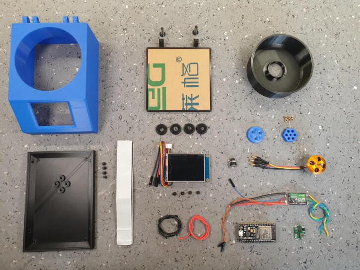
All parts needed to build Maasi excluding the tools and consumables.
Setting up the ESP32
-
1.
Copy the “ITEADLIB_Arduino_Nextion” to Arduino library folder
-
2.
Open the Arduino IDE
-
3.
File > Preferences > Additional Boards Manager URLs-> Add “https://dl.espressif.com/dl/package_esp32_index.json”
-
4.
Tools > Board:>Boards Manager-> Install ESP32
-
5.
Tools > Manage Libraries…->Install “PID” by Brett Beauregard and “elapsedMillis”
-
6.
Connect the ESP32 to the PC
-
7.
Tools > Board:-> Select ESP32 Dev Module
-
8.
Tools > Port-> Select the corresponding COM Port
-
9.
Click on Upload
Setting up the Nextion Display
-
10.
Copy the “maasi_v1.tft” file to a microSD card.
-
11.
Insert MicroSD card into the Nextion Display.
-
12.
Power the Nextion Display.
-
13.
Wait for the flashing to complete.
-
14.
Power off the Nextion.
-
15.
Remove the micro-SD card.
Setting up the BLHeli_32 ESC
-
16.
Install and open the BLHeliSuite32.
-
17.
Connect the Arduino uno to the PC with a USB cable.
-
18.
Make Interfaces (Tab)-> Select Arduino BLHeli Bootloader.
-
19.
Select COM Port.
-
20.
Click on “Arduino BLHeli Bootloader” to flash.
-
21.
Connect Arduino pin 11 to the signal pin of the ESC. Also connect the ground pins.
-
22.
Power the ESC with 12 V DC with a lab power supply or with the power adapter.
-
23.
Connect the Arduino uno to the PC with a USB cable.
-
24.
Select BLHeli_32 Interface > BLHeli32 Bootloader (USB/Com).
-
25.
ESC Setup (tab)-> Select corresponding COM Port.
-
26.
Connect.
-
27.
Read Setup.
-
28.
ESC Flash (tab)->Flash to 32.7 version(Not newer).
-
29.
Flash Selected ESC.
-
30.
ESC Setup (tab) -> Read Parameters
-
31.
Change “Beacon Delay” to 60 mins (optional).
-
32.
ESC Setup (tab) -> Write Parameters
Putting together the hardware
-
33.
Solder about 20 cm of black and red cable to the power connector and install it in the case.
-
34.
Solder the power cable and the ESC power cables to the DC-DC input terminals.
-
35.
Adjust the DC-DC output voltage to 5 V (if necessary).
-
36.
Solder about 25 cm of black and red cable between the output DC-DC and the display power connector pads.
-
37.
Install the display in the housing using four M3x12mm bolts.
-
38.
If necessary, solder the telemetry cable to the ESC.
-
39.
Solder the three motor phases to the ESC in any order.
-
40.
Install the rubber feet on the base with M3 bolts.
-
41.
Install the motor on the 3D printed base with M3 bolts. Note that the motor sits in a specific orientation.
-
42.
Fix all the electronics with hook-and-loop adhesive tape.
-
43.
Connect the remaining cables between the ESC, the ESP32 and the display.
-
44.
Ensure that all connections are made as shown in the circuit diagram (Fig. 5).
-
45.
Power up Maasi and make a test run with the default parameters.
-
46.
Screw the case to the base.
-
47.
Add the vase and the motor adapter.
-
48.
Insert the 100x100mm transparent lid in the hinge frame.
-
49.
Use two M4x20mm tapered screws to join the lid to the case.
Fig. 5.

Connection diagram of Maasi.
Operation instructions
Warning: This machine can spin at very high rates and protective eye equipment is recommended
-
1.
If needed, create a new substrate holder from the main design file and 3D print it.
-
2.
Insert the substrate holder on the hexagonal shaft adapter and fix it with countersunk M3 bolts.
-
3.
Connect the power connector. The screen will show the main menu with default values.
-
4.
Place the substrate on the holder.
-
5.
Set the target speed and coating time. Additional parameters are available in the Settings Menu.
-
6.
Click on the green button to start the dispense phase.
-
7.
Apply the solution onto the substrate and close the lid.
-
8.
Click on the green button again. Coating will start
-
9.
Wait until the countdown is finished to open the lid.
-
10.
Remove the coated substrate.
Validation and characterization
To validate the performance of the device a series of measurements were conducted. Two Maasi prototypes were built and integrated in the routines of two different labs to find potential bugs in the HMI and other user experience problems. This led to some improvements in the mechanical design like the addition of the protective lid and bigger rubber feet. The second prototype was underperforming, and further investigation revealed that a newer version (v32.8) of the ESC firmware was causing the drop in performance.
Speed accuracy measurements
To characterise the Maasi spin coater performance a study of the speed accuracy was conducted. Before this study a custom tachometer was built using a generic infrared obstacle sensor and a Rigol DS1054z oscilloscope (Fig. 6). The sensor drives the signal low when a reflection is detected and the threshold can be adjusted with a built- in potentiometer. It was held in place pointing towards the rotating parts with a laboratory clamp.
Fig. 6.

Speed accuracy experiment set-up. A) Speed measurement being conducted at 600 RPM. B) First test (High load) with the microscope-slide in the holder. C) Second test (No load) with the aluminium tape in the shaft adapter.
The first test was performed with a high load, a 75x25mm microscope slide, frosted on one side and inserted on its corresponding 3D printed substrate holder. The frosted side was detected by the sensor generating one pulse per revolution.
The second test was performed without load. A strip of aluminium tape was placed on the shaft adapter to trigger the sensor similarly one time per revolution.
The oscilloscope’s statistical analysis tools were used to analyse the averaged pulse frequency and its standard deviation during a period of 20 s (Fig. 7).
Fig. 7.

Experimental data of the rotors velocity with and without load. A) The accuracy measurements were limited by the resolution of the oscilloscopes statistical module and show a strong overlap. B) The deviation shows a similar increase with the set speed in both cases.
Underlying the increase of the standard deviation with the speed there is an increasing noise of the speed measurements within the ESC. This error in the speed estimation produces instability in the velocity control loop and newer versions of the BLHeli firmware (v32.8) showed a regression in this regard. Thus, setting a performance barrier due to the closed source nature of that software. To improve the performance of Maasi, the project could explore the use of modern open-source ESC firmwares (i.e. bluejay) or switch to a more classical approach using a tachometer.
Example of application: PDMS coating for immunology assays
As part of the preparation for another study [6], a series of coating thickness measurements were conducted for PDMS (QGel920A/B, ratio 1:2, Quantumsilicons). Prior to the spin coating, the PDMS was mixed and later degassed in a vacuum chamber for 8 min. The substrates were prepared using 18 mm round high-precision cover glasses with thickness No. 1.5H. Tetraspeck fluorescent beads were absorbed on the cover glass prior to spin coating of PDMS and again after annealing at 80C° for 12 h in the oven. Thus, offering two focusing planes for PDMS thickness determination Fig. 8. Using fluorescence microscopy, four regions of interest were measured using an Eclipse TE2000 Nikon microscope equipped with a Prior Nano-positioning Piezo Z Stage, for z positioning.
Fig. 8.

Experimental validation. Schematics of the sample design with Tetraspeck beads below and above the PDMS hydrogel.
Four regions of interest were sufficient to determine the set speed needed to achieve a coating thickness between 25 and 30 µm required by the application Fig. 9. More demanding applications requiring PDMS spin coating such as soft lithography should use precise measurement techniques like optical profilometry [17].
Fig. 9.

PDMS mean thickness measured using fluorescence microscopy is plotted versus the set speed of the Maasi spin coater. The spin coating duration was 40 s with an acceleration time of 2 s.
Device Specifications:
-
•
Min set speed: 300 RPM
-
•
Max set speed: 8000 RPM
-
•
Speed accuracy: >98%
-
•
Speed resolution: 100 RPM (Customisable down to 14 RPM)
-
•
Maximum coating time: 80 s (Customisable in firmware up to 35791 min)
-
•
Time resolution: 1 s (Customisable in firmware down to 1 ms)
-
•
Max substrate diameter: 80 mm
-
•
Materials: PLA (body, vase, holders), PMMA(transparent lid)
-
•
Supply: 12 V 4A via 100-240v 50/60 Hz power adapter.
Human and animal rights
No humans or animals were harmed in this study.
Declaration of Competing Interest
The authors declare that they have no known competing financial interests or personal relationships that could have appeared to influence the work reported in this paper.
Acknowledgments
The work was supported by the Human Frontiers Science Program RGY0065/2017 and VW Stiftung Experiment! Grant 95664.
Biography
Dani Carbonell received his bachelor's degree in Industrial Electronics from the Valencia Polytechnic University (UPV). After his Erasmus exchange program in the ETH Zürich he focused his interest in mobile robotics and ultrafast lasers. Currently he is a visiting scientist at the Experimental Biophysics/Mechanobiology group at the Humboldt University of Berlin. His research is focused in the development of affordable lab tools relating to microscopy, microfluidics, sample preparation as well as bioimage analysis.
Contributor Information
Dani Carbonell Rubio, Email: carboned@hu-berlin.de.
Enrico Klotzsch, Email: enrico.klotzsch@hu-berlin.de.
References
- 1.Booeshaghi A.S., Beltrame E.d.V., Bannon D., Gehring J., Pachter L. Principles of open source bioinstrumentation applied to the poseidon syringe pump system. Sci. Rep. 2019;9 doi: 10.1038/s41598-019-48815-9. [DOI] [PMC free article] [PubMed] [Google Scholar]
- 2.B. Krasnow, Design and build a spin coater, 2016. https://www.youtube.com/watch?v=321tptQ8PrU (accessed January 20, 2022).
- 3.Emslie A.G., Bonner F.T., Peck L.G. Flow of a viscous liquid on a rotating disk. J. Appl. Phys. 1958;29:858–862. [Google Scholar]
- 4.Meyerhofer D. Characteristics of resist films produced by spinning. J. Appl. Phys. 1978;49:3993–3997. [Google Scholar]
- 5.Y. Mouhamad, P. Mokarian-Tabari, N. Clarke, R.A.L. Jones, M. Geoghegan, Dynamics of polymer film formation during spin coating, Journal of Appl. Phys. 116 (2014) 123513. https://doi.org/10.1063/1.4896674.
- 6.Aramesh M., Mergenthal S., Issler M., Plochberger B., Weber F., Qin X.-H., Liska R., Duda G.N., Huppa J.B., Ries J., Schütz G.J., Klotzsch E. Functionalized bead assay to measure three-dimensional traction forces during T-cell activation. Nano Lett. 2021;21:507–514. doi: 10.1021/acs.nanolett.0c03964. [DOI] [PubMed] [Google Scholar]
- 7.L. Instras Scientific, Instras SCK-300, Instras Store. (2021). https://instras.com/index.php/store/ (accessed August 24, 2021).
- 8.Ossila, Spin Coater Model: L2001A3-E461-EU, Ossila Shop, 2021. (2021). https://www.ossila.com/products/spin-coater (accessed August 24, 2021).
- 9.Sadegh-cheri M. Design, fabrication, and optical characterization of a low-cost and open-source spin coater. J. Chem. Educ. 2019;96:1268–1272. doi: 10.1021/acs.jchemed.9b00013. [DOI] [Google Scholar]
- 10.Bianchi R.F., Panssiera M.F., Lima J.P.H., Yagura L., Andrade A.M., Faria R.M. Spin coater based on brushless dc motor of hard disk drivers. Prog. Org. Coat. 2006;57:33–36. doi: 10.1016/j.porgcoat.2006.05.004. [DOI] [Google Scholar]
- 11.Kaddachi Z., Belhi M., Ben Karoui M., Gharbi R. 2016 17th International Conference on Sciences and Techniques of Automatic Control and Computer Engineering (STA) 2016. Design and development of spin coating system. [DOI] [Google Scholar]
- 12.C. Landa, DSHOT Protocol, Brushlesswhoop.com. (2021). https://brushlesswhoop.com/dshot-and-bidirectional-dshot/ (accessed November 29, 2021).
- 13.S. Skaug, BLHeli Firmware, Github. (2018). https://github.com/bitdump/BLHeli/tree/master/BLHeli_32%20ARM (accessed November 29, 2021).
- 14.Flyduino, KISS ESC 32-bit series onewire telemetry protocol, 2016. http://www.rcgroups.com/forums/showatt.php?attachmentid=8524039&d=1450424877 (accessed January 20, 2022).
- 15.ITEAD STUDIO, Nextion Editor, Nextion. (2019). https://nextion.tech/nextion-editor/ (accessed February 28, 2022).
- 16.L. Llc, LVGL - Light and Versatile Embedded Graphics Library, LVGL. (2022). https://lvgl.io/ (accessed January 20, 2022).
- 17.J.H. Koschwanez, R.H. Carlson, D.R. Meldrum, Thin PDMS films using long spin times or tert-butyl alcohol as a solvent, PLoS ONE. 4 (2009) e4572. https://doi.org/10.1371/journal.pone.0004572. [DOI] [PMC free article] [PubMed]